Transcription
MECH 410 and MECH520Computer-Aided DesignIntroductionModern CAD/CAE/CAM Tools andTheir ApplicationsZuomin Dong, ProfessorDepartment of Mechanical EngineeringCAD (Mechanical Design Automation)State of the Art An Essential Tool for Mech. Design and Drafting– Millions of mechanical engineers and designers worldwideuse advanced 3-D solid modeling technology (1M in 2000)– Even more are using 2-D mechanical drafting (2M in 2000) A Key for Improved Productivity– Entire automobiles, airplanes, and jet engines are beingdesigned in an integrated (CAD/CAE/CAM) manner.– Internet is beingg used to exchangeg designg data worldwide.– Products that previously took several years to bring tomarket can be developed in just months.– The products are more reliable, meet customer expectationsbetter, and are less costly to manufacture.1
Broad Applications, Many Systems andRapid Advance of Technology Mechanical Design and Visualization– DetailedD il d DDesigni andd ElElectronici DDraftingfi– Parametric Modeling Motion Simulation/Animation Engineering Analysis and Optimization– Pre- and Post- Graphical Processors for Finite Element Analysis(Mechanics, Dynamics, Thermo-flow, etc.)– Identification of Optimal Design Parameters and Configurations– Motion Analysis (Location, Speed, Acceleration and Force) Manufacturing Planning of Simulation– Machining– Industrial RobotsApplications in Mechanical Designs2
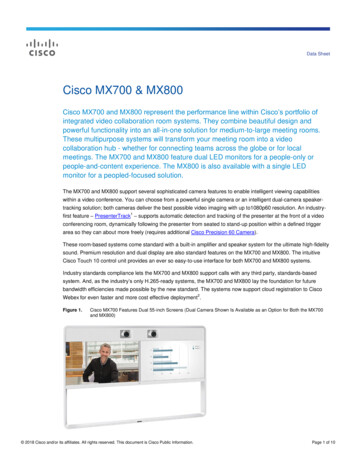
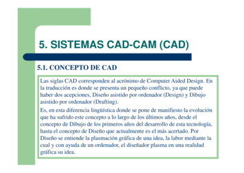
Sculptured Surface Design and ModelingMotion Concept Vehicle, Mississauga, OntarioVisual Reality in Architectural Design3
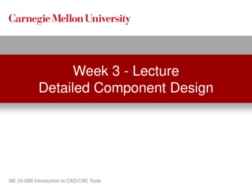
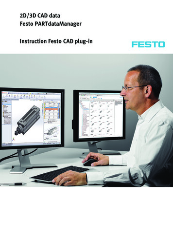
Motion Animation and Simulation(Tractors)Applications in Stress Analysis4
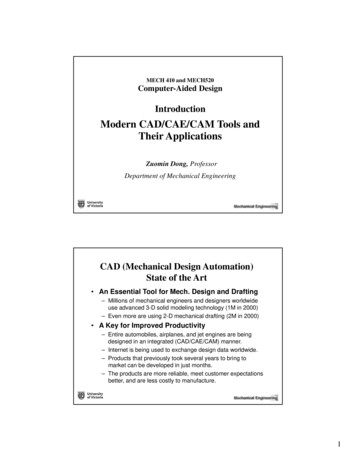
Workspace and Sequence SimulationErgonomics and accessibility test (Jack and Jill)Integrated CAD/CAE/CAM Systems Professional CAD/CAE/CAM Tools––––CATIA (Dassault Systemesy- IBM))Unigraphics NX (Electronic Data Systems Corp - EDS)I-DEAS (EDS)Pro/ENGINEER (PTC) Other CAD and Graphics Packages–––––AutoCAD Mechanical DesktopSolidWorks (CATIA)Solid Edge (EDS)MicroStationIntergraph5
Fuel Cell Vehicle Modeling and Analysis Using Pro/EEcoCAR HEV Design and Analysis Using Unigraphics NXIntegrating the GM 2-Mode Transmission into the EcoCARDesign Team: David Robinson, Degnan Hembroff and Michael Versteeg6
University of Victoria, B.C. Canada7
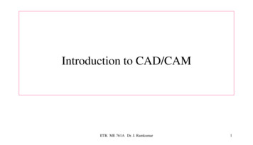
EcoCAR HEV Design and Analysis Using Unigraphics NX2-Mode AWD Plug-in Hybrid Vehicle Architecture DesignElectrical Team: Jonathan Cronk, Dian Ross, & Mechanical Team: Ian LougheedCargo Envelope (forEmissions measurementequipment)Battery Envelope.2205 m3 for 20 kWhStock VUE mufflerlocationEcoCAR HEV Design and AnalysisElectric Rear Wheel Drive GearboxAdam Binley, Jake Soepber, Kyle McWilliam, Bryce Donnelly, Yoshua Ichihashi & Sean Walsh8
EcoCAR HEVDesign andAnalysis UsingUnigraphics NXCATIAUnigraphicsIntegrated CAD/CAE/CAM Systems Professional CAD/CAE/CAM Tools––––CATIA (Dassault Systemesy- IBM))Unigraphics NX (Electronic Data Systems Corp - EDS)I-DEAS (EDS)Pro/ENGINEER (PTC) Other CAD and Graphics Packages–––––AutoCAD Mechanical DesktopSolidWorks (CATIA)Solid Edge (EDS)MicroStationIntergraph9
Pro/ENGINEER One of the CAD/CAM/CAE industry’s leading suppliers ofsoftware tools from Parametric Technology Corp. (PTC) A pioneer of the new feature-based, parametrically drivendesign paradigm in late 1980s, now industrial standard. A system used to automate the development of a mechanicalproduct from its conceptual design through production. Offering integrated software technologies to reduce time tomarket, improve engineering process, and optimize productq alitquality. One of the fastest growing companies in the mechanicaldesign automation market Improved user’s interface in recent release.Pro/ENGINEER10
Unigraphics A full spectrum design modeling, analysis, simulation,and manufacturing CAD/CAE/CAM software fromUnigraphics Solutions One of the older and well-established CAD/CAEsystem. A software of choice for a wide variety of applications,especially in automotive and aerospace productddevelopment.ltUnigraphicsAutomotive & AerospaceVirtual ProductDevelopment Process11
CATIA A process-centric CAD/CAM software solution marketedexclusively by IBM and developed by Dassault Systems A systemtusedd tot designd i andd manufacturef tmany complexl3D products. Today, 7 out of every 10 airplanes and 4 outof every 10 cars are designed using CATIA-CADAMSolutions, making it the de facto standard for thesemarkets. A software of choice for a wide variety of applicationsg g from consumer ggoods and machineryy to pplantrangingdesign and shipbuilding. 300,000 CATIA users worldwide, nearly half in Englishlanguage marketsCATIA12
I-DEAS A full spectrum design modeling, analysis, simulation, andmanufacturing CAD/CAE/CAM software from StructuralDynamics Research Corporation (SDRC) One of the older and well-established CAD/CAE system,having a significant market share. Having very strong CAE capabilities A software of choice for a wide variety of applicationsranging from consumer goods and machinery toautomotive (Ford Motor Company)I-DEAS13
Solid Edge Powerful modeling tools Integrated design management Productivity for large assemblies Ease of adoption Model faster Eliminate errors with engineering aids Drafting tools Unmatched interoperability Design-through-manufacturingSolid Edge14
AutoCAD and Mechanical Desktop A world’s leading PC-based 3D mechanical designpackage, from AutoDesk Inc. Used to be the primary PC drafting package (dealer, PC) The world’s most popular CAD software due to its lowercost and PC platform New features (Mechanical Desktop):– ACIS 3.0 Advanced Solid Modeling Engine– NURBS Surface Modeling– Robust Assembly Modeling and Automated AssociativeDrafting Flexible programming tools, AutoLISP, ADS and ARXCAD Applications through Programmingin AutoCAD15
SolidWorks 3D Computer-aided Mechanical Design softwarefrom SolidWorks Corp. founded in 1993 and acquiredbe Dassault System in 1997. A leader of the group of new lower-priced mechanicaldesign solution companies based upon componentsoftware. A system used for designing and engineering partsand assemblies in a completed 3D-centric processlinked to automated assembly and drafting functions. The first solid modeling program to run in nativeWindows environments, and sells for a fraction of thecost of similar programsSolidWorks - COSMOSSolidWorks - a design automation software package used to produceparts, assemblies and drawingsPackage fully embedded within SolidWorks software COSMOSXpress - an easy-to-use stress analysis tool COSMOSWorks - stress, frequency, buckling, thermal, andoptimization analyses COSMOSMotion - motion simulation and kinematics. COSMOSFloWorks - fluid flow analysis with robust capabilitiesnormallyo a y foundou d in high-endg e dCCFD pprograms.og a s COSMOSEMS - 3D-field simulator for low frequencyelectromagnetic and electromechanical applications COSMOSDesignSTAR is a powerful design analysis programthat works with most popular CAD programs.16
MicroStation A premier CAD software for infrastructure engineeringand major architectural and civil engineering fromB tl Systems,BentleyS tIncorporated,It d theth worldwideld id lleaderd iinengineering software products, user services andoverall quality. The software foundation underlying the engineering ofwell-known buildings, airports, hospitals, highways,bridges and industrial plants throughout the world, usedin over 70% of the largest US engineering firmsfirms. Bentley System now serves over 250,000 professionalsin construction engineering, geo-engineering, andmechanical engineering fields.Integrated CAD/CAE Tools ANSYS (from ANSYS Inc.)– A growth leader in CAE and integrated design analysis andoptimization (DAO) software– Coveringg solid mechanics,, kinematics,, dynamics,y, and multi-physicsp y(CFD, EMAG, HT, Acoustics)– Interfacing with key CAD systems NASTRAN (from MacNeal-Schwendler)– A powerful structural analysis program for analyzing stress,vibration, dynamic, nonlinear and heat transfer characteristics.– PATRAN provides an open flexible MCAE environment for multidisciplinary design analysis, and simulates product performanceandd manufacturingf t i processes. Pro/MECHANICA (integrated with Pro/E)A system provides an open flexible MCAE environment for multidisciplinary design analysis, and simulate product performance andmanufacturing processes.17
Integrated CAD/CAM Tools Mastercam (from CNC Software, Inc.)– A system for generating 2- through 5- axis milling, turning,wirei EDMEDM, llasers, moldld bbase ddevelopmentlt andd 3D ddesigniand drafting. Virtual Gibbs (from Gibbs and Associates)– A powerful, full featured CAM system for NC programming Varimetrix (from Varimetrix Corp.)– A system with design modeling, CAM (planning, resourcemanagement and CNC programming)programming), and drafting Pro/MANUFACTURING (integrated with Pro/E)– A system for generating machine code (CNC codes for 3axis milling, turning and wire EDM) to produce parts.VirtualGibbs18
Integrated CAD/CAM Tools SURFCAM (from Surfware Inc. CA)– An outgrowth of the Diehl family’smachinehi shoph– A system for generating 2 5- axismilling, turning, drilling, and wire EDM.– Toolpath verification (MachineWorks Ltd.) Rhinoceros (NURBS modeling)– Industrial, marine, and jewelry designs;cad/cam; rapid prototyping; and reverseengineeringRapid PrototypingSolid Freeform FabricationBuilding a solid part directlyfrom a CAD model, layer bylayer, by material deposition. Sterolithography, SLA Selective Laser Sintering, SLS Laminated Object Modelling, LOM FusionF i DDepositioniti Modelling,M d lliFDM 3-D Printing Solid Ground Curing, SGC Shape Deposition Manufacturing, SDM19
Stereolithography SLA employs an ultraviolet laser to cure a thin layer of liquidplastic into a solid. The process operates by taking a thin layer of light-sensitive liquidplastic and passing the beam of a laser over the points where the part is to be solid. Oncea pass is complete, another layer of liquid is added to the existing part and the process isrepeated until the entire part is constructed.How to Teach Computer-Aided Design?What to teach? ElectronicEl t i draftingd fti usingi aCComputer-Aidedt Aid d Drafting systemDesign modeling using an advancedCAD/CAE/CAM systemComputer graphics and data structureEngineering optimizationFinite element analysisSoft prototypingCustomization of CAD systems20
MECH410/520 Computer-Aided Design Computer Graphics Theory– Geometric transformation and geometric modeling– Curves and surface modeling AdvancedAdd CAD/CAE SSystemt– Pro/ENGINEER design modeling, assembly, and drafting– Pro/MECHANICA structure and motion analysis– Other Pro/E functions (automated CNC tool path generation) An Introduction to Design Optimization– Formulating a design optimization problem– Common optimization solution methods– Major issues in design optimization Interactive Graphical Programming– Programming in AutoCAD for design, analysis, simulation, etc.– Programming in Pro/E Application of Integrated CAD/CAE/CAM Systems– Virtual prototyping; design optimization; & rapid prototypingTechnology Advance of CADIn 1960's mechanism design satisfying several geometric constraints design parameter optimization simple 2-D graphicsIn 1970's wireframe modeling free-form surface modeling – mainframe computersLate 1970's solid modelingEarly 1980's turn-key CAD systems CAD/CAM integration mechanical feature recognition from a CAD databaseComputer-Aided Design21
Technology Advance of CADMiddle 1980's feature-based CAD system parametric design(Pro/ENGINEER Products)– mini and micro computers– PCPC'ss & Turnkey systemsLate 1980's design for manufacturing design for automated assemblyEarly 1990's concurrent engineering design integratedi tt d design,d ianalysisl i andd optimizationti i tiPresent integrated design, analysis and optimization virtual-prototyping and automated design optimization Internet based design automationComputer-Aided DesignUnique Characteristics of A CAD System Combiningg the pprecision of electronic ggraphicspand themathematical processing power of a digital computer Design automation and integration of analysis,animation/simulation, planning and manufacturing OptimizationComputer-Aided Design22
Functions of CAD Systems The Primary Capability – Generating Perfect ScaleDrawings– accurate scale line drawings in 2D and 3D– model of sculptured surfaces– solid model of objectsThis capability sets CAD apart from other uses ofcomputer Many Diverse Capabilities––––artistic creation of shaded 3D shapesp and ppatternsautomatic generation of design databasesfacilitating engineering analysisproviding input to, monitoring, simulating and controllingmanufacturing activities.Computer-Aided DesignFunctions of Computer-Aided GeometryDesign – (a)Specification of Design Geometry Computer-aided drafting (interactive graphics and user interface) Customizing CAD systemsGeometric Modeling and Representation Computer model of part and assembly design (data structure and database design)Visualization Architecture view of a design Computer games and education programsGeneration of Manufacturing Oriented Database Feature-based design Parametric designAnimation and Simulation MechanismCNC machiningRobot trajectoryAutomobile crashComputer-Aided Design23
Functions of Computer-Aided GeometryDesign – (b)Tolerance Representation and Automated Tolerancing Dimension relation analysisyTolerance analysis (error stack-up)Tolerance synthesis (tolerance design, tolerance specification)Pre- and Post-interfaces to Finite Element Analysis Programs Automated mesh generationGraphical display of stress distributionDesign Automation Design optimizationD i ffor manufacturingDesignf t iDesign for automated assemblyConcurrent engineering designVirtual (or Soft) PrototypingReverse EngineeringComputer-Aided DesignInformation Embedded in a CAD System Graphical Information– Part geometry– Topological and assembly relations Textual Information––––DimensionsTolerances (dimensional & geometric)MaterialsSurface finishesComputer-Aided Design24
Data Organization in CAD Systems Past ApproachThe geographical information is represented using lowlevel graphical elements such as points, lines, arcs, etc.The textual information is represented as texts, notes andsymbols attached to a drawing. Ideal/Present Approach – feature-based modelingTo represent part geometry using high-level featureprimitives such as holes, slots, pppockets, etc. ((consistent tothe engineering practice), and to represent dimensions,tolerances, surface finishes, etc. as meaningful designentities.Computer-Aided DesignTools Commonly Used in Computer Aided Design Representing geometric shape– Computer graphics (2D)– Geometric modeling (3D) Interactive Graphical Programming– PProgrammingi on diffdifferentt platformsl tf– Graphical User Interface Manipulating and storing design data– Data structure design– Database system Generating feasible designs (automatically)––––Knowledge reasoningKnowledge-based systemFuzzy logicArtificial neural networks Evaluating design alternatives and identifying the optimal solution– numerical optimization– finite elements method– cost modeling and analysisComputer-Aided Design25
PACE - Partners for the Advancement ofCAD/CAM/CAE EducationTo integrate 3-D solid modeling and other parametrics-based CAD/CAM/CAEapplications (Unigraphics-related) into the curriculaof strategically selected academic institutions worldwide (1999-) Participating Industry– General Motors Corp.,– Sun Microsystems, and– EDS Donations– computer-aided design, manufacturing, and engineeringsoftware Unigraphics, IDEAS, SolidEdge––––hardware (Sun workstations) andtraining to universitiesautomotive parts, andcollaborative industry projects for students.Computer-Aided DesignUniversities Receiving A PACEDonation A long-term relationship with GM as a primary educational partner A strong product development and manufacturing curriculum An adequate infrastructure of facilities, maintenance systems andpersonnel to support the donated hardware and software A willingness to integrate Unigraphics software into theengineering curriculum Participants– Michigang State University;y Michigang TechnologicalgUniversity;y Universityyof Missouri-Rolla; Tuskegee University; Kettering University;Northwestern University; Prarie View A&M University– University of Toronto; University of Waterloo; Queens University;University of British ColumbiaComputer-Aided Design26
Academic Product Bundles from PLMSolutions Unigraphics NX, I-deas NX Series, Solid Edge, E-Factory, Teamcenter, Parasolid and Open Enterprise Visualization Applications Software.Computer-Aided DesignLarger AssembliesHermle CNC assembly comprises 1,300 unique parts—4,000 components totalComputer-Aided Design27
Machines High-Tolerance SurfacesComputer-Aided DesignStress Analysis(both shell and solid elements)Computer-Aided Design28
Photorealistic Rendering of Conceptsor Finished ModelsComputer-Aided DesignIntegrated Digital Simulation andSystem-based ModelingComputer-Aided Design29
UnigraphicsUGACAD100, UGACAD300 (initialization/renewal)I-DEASA502Solid EdgeSE292-ENG-MT, SE293 (SE w/ UG & or I-DEASSE291 (Single User)E-FactoryEFACAD100, EFACAD102, VS10414, EFACAD300OEVOEVACAD102, OEVACAD103, VS20515OEVACAD300 (initialization/renewal)FEMAPE004: FEMAP Professional Floating, E302: FEMAPStructure Solver, E009: FEMAP Demo (no cost)TeamCenterModulesIM11500: iMAN e-Server,, IM11520: iMAN Author LicenseIM11650: iMAN UG/ Integration, PV11805: Product VisionPortal ViewerSLATEModulesSL8-3611: SLATE Architect, SL8-3622: SLATE RequireSL8-3666: SLATE Activator Authoring, SL8-3699: SLATEComputer-Aided Design30
disciplinary design analysis, and simulates product performance andftid manufacturing processes. Pro/MECHANICA (integrated with Pro/E) A system provides an open flexible MCAE environment for multi-disciplinary design analysis, and simulate product performance and manufacturing processes.