Transcription
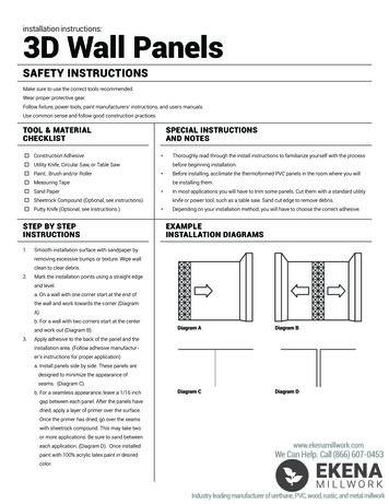
HIDDENGUTTERSYSTEMInstallationinstructions1. Notes before installation1.11.21.31.41.51.61.7Installation of the HIDDEN GUTTER System should beperformed on the basis of the design documentationprepared by the architect responsible for the givenconstruction site. Any attempt to mount the system withoutpreviously prepared documentation may cause the systemto malfunction.o ensure optimal functionality and system tightness, werecommend using highly qualified designers and roofers.Installation of the GALOCO HIDDEN GUTTER System shouldbe performed using dedicated materials described in thisManual.The Galeco HIDDEN GUTTER System should not beinstalled when ambient temperature is lower than 5 C.Drawings given in this Manual are of an informationalnature only, and cannot be used as workingdocumentation.When designing the Galeco HIDDEN GUTTER Systemfor a given building, special attention should be paid toreinforcing the external wall structure and the tie beam innarrowings.Variable parameters such as roof pitch, method of tiebeam reinforcement, rafter plate-tie beam connection,roofing material, dimensions of the roof truss elements,rafter plate foundation height and thickness, and the typeof roof insulation differ in each building. The parametersshould be selected individually depending on the project.1.8 The gutter system should be installed to straight sectionsso that it does not have vertical and horizontal deviationsother than variation allowable by the applicablestandard for a given base the system is mounted on,resulting from the the way the overlap connectionsgutter-gutter, gutter-outlet, gutter-corner, cover-coverare made.1.9 System gutters can be mounted horizontally or with a smallslope of 1 mm per 1 running meter. If a slope is required,allow for the difference in height of the cover fixed to thebrackets , which amounts to about 1 cm per 10 runningmeters of gutter.1.10 Overlap assembly of components made of sheet metalcan cause natural deviations in straightness of the longcomponents.1.11 Installation of the Galeco HIDDEN GUTTER System shouldbe carried out when insulation of the building is installed,so that drainage components can be installed inside theinsulation.1.12 Downpipes of the Galeco HIDDEN GUTTER System mustbe completely hidden in the wall and connected belowground level to the storm water drainage system.1.13 The system should be designed and installed in such away to avoid connecting the downpipes at angle in thewall and so that pipes hidden in the façade does not runvertically without any slopes.Galeco HIDDEN GUTTER System1
1.14 The Galeco HIDDEN GUTTER System should be designedand installed in such a way that no cold bridge/freezingpoints occur behind the gutter and the downpipe andto ensure effective transfer of moisture away from theinsulation layers.1.15 The minimum thickness of the outer wall insulation layer thesystem can be installed in is 16 cm. If the outer insulationlayer is thinner than 20 cm, a groove must be cut in theload-bearing wall. The downpipe groove in the buildingwall should be at least 30 cm wide and should havedepth according to architectural drawings adapted to theimplemented project1.16 If it is not possible to make a groove in the wall, theinsulation material thickness behind the downpipe shouldbe increased accordingly or material of better parametersshould be used to eliminate cold bridges.1.17 In the area where the downpipe is routed, insulation shouldalways be placed behind the downpipe. If the insulationlayer is too thin, it is also possible to place insulationmaterial in front of the downpipe, but cold bridges mustbe eliminated in this area of the external wall as a firstpriority.1.18 In order to ensure the long-term and effective operationof the Galeco HIDDEN GUTTER System, inspection andgutter cleaning should be carried out at least twice a year.If the building structure is subject to significant exposure toexternal factors, the system should be checked more often.Inspection and maintenance of the gutter system shouldinclude removing all debris (leaves, needles, etc) fromthe gutter, checking that the downpipes and drainagecomponents are clog-free and removing all dirt from thesediment tank.1.19 The manufacturer recommends installation of Galecobaskets for additional protection of the drainage lineagainst leaves and other foulants (Fig. 1)1.20 In order to avoid damage to the system caused by snowand ice, it is recommended to install snow fences and theheating cable system offered by Galeco (Fig. 1) - heatingcable assembly instructions are available at www.galeco.pl in the tab Downloads/Installation instructions.1.21 The manufacturer allows slight differences in shade orgloss within products of the same colour due to differenttechnological process used in the production of powdercoated elements.1.22 The Galeco HIDDEN GUTTER System works on the principleof gravity, not a vacuum drainage of rainwater.Fig. 12. System designDue to the complexity of the system and its installation ina wall groove inside the building insulation, the system shouldbe designed by a professional architect at the stage ofcreating the building architectural and construction design.When designing a Galeco HIDDEN GUTTER System, take thefollowing into consideration: the number of long components: gutter, cover, downpipe the number of gutter fittings: bracket, butt connector, outlet,right and left end cap the number of downpipe fittings: elbow, sleeve, clamp,Ø 80/110 adapter, sedimentation tank To calculate the number of the downpipes correctly, thecapacity of the system and good building practices must betaken into consideration.The recommended distance between successive downpipes is12 meters.After comparing the table data with the surface to be drained,choose a suitable number of downpipes for a given building.The data in the table specify the maximum roof surface fromwhich a single downpipe of the system can drain water, withthe downpipe situated at the corner or on the wall.Roof area in m 2 (C/2 B) x roof length.Galeco HIDDEN GUTTER System2
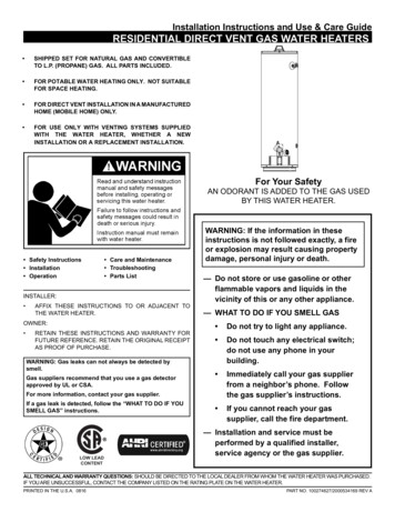
Capacity tableDownpipe positioningSystem efficiency*90 m2180 m2The above calculations are made on the assumption thatprecipitation intensity is 75 mm/h and the maximum roof pitchis 50 degrees. For roofs having a pitch lower than 10 degreesor flat roofs, the maximum Effective Roof Area equals the roofarea.3. Gutter installation3.6 Fill the groove with insulating material (Fig. 3)3.7 For proper operation of the system, it is necessary to installa verge trim, which is one of system components suppliedby Galeco . The length of the trim is 2 meters (Fig. 3).The verge trim can also be made by the roofer on site(Fig. 4, 5)3.8 Verge trim made on site should meet four basicrequirements:3.1 The gutter should be positioned in relation to the roofend in such a way that the theoretical line drawn as itsextension passes over the outer edge of the gutter (seethe example application in (Fig. 2) and that rainwaterfalls into the gutter. If due to the construction of the roof,the line passes below the outer edge of the gutter, snowfences should be installed on the roof to protect the gutterfrom damage caused by sliding or piled up snow.3.2 Design the position of the gutter relative to the futurefaçade. For this purpose, determine the protrusion of therafter edge beyond the outer edge of the load-bearingwall using the formulaX Y - 14 - ZX [cm] - distance of the rafter protrusion inside the cavityY [cm] - insulation thickness façade finishZ [cm] - fascia board thickness16 [cm] - width measured from the cover front to the rearsurface of the bracket- it should have a slope in the horizontal section ofa minimum of 94 , enabling moisture to be moved awayfrom the façade (Fig. 4-5)- the vertical part of the verge trim should have aminimum height that will cover the entire part of theeaves board above the gutter;- the verge trim should have a drip on its outer partenabling moisture to be moved away from façade;- the horizontal part of the verge trim should havea minimum width so that the above drip protrudesa minimum of 1 cm beyond the face of the finishedfaçade.3.3 Install a fascia board of a material which will guaranteeno horizontal and vertical deformations and resistance toexternal conditions. The fascia board should be mountedso that its face constitutes a single, smooth and verticalsurface. The surface should not have longitudinal slope inany direction.3.4 It is recommended to install a horizontal shelf togetherwith the fascia board, which will provide the necessarysupport to install the verge trim properly.3.9 In order to ensure 100% tightness of the verge trim (bothfactory made and roofer made), elements must be joinedwith each other tightly e.g. by an adhesive with 7 cmoverlap or using a flat seam.3.5 The thickness and type of insulation behind the downpipeshould guarantee elimination of cold bridges. For thispurpose, making an additional groove behind the pipemay be required, according to Points 1.15 and 1.16 of thisManual. (Fig. 2)Fig. 21614320.0 0.2940130141140.9 0,50.6159Fig. 3Fig. 44011142.7 0.5150.2 0.5Fig. 5Galeco HIDDEN GUTTER System3
3.10 The verge trim joints should be displaced in relation to thegutter/gutter, gutter/outlet, gutter/corner connection bya minimum of 50 cm. After installation, the bottom shelf ofthe verge trim should have its slope directed outwards.3.11 The next step is to install special fascia brackets, formingthe cover frame. Set the beginning and the end of thegutter line and tighten the end brackets (Fig. 6)3.12 Stretch a string between the outermost brackets, drawa line and mount the remaining brackets. The maximumrecommended bracket spacing is 60 cm. (Fig. 7-8) - showthe correct installation of the brackets.3.13 Brackets should be installed to the left and right side ofthe outlets, expansion joints and corners at a maximumdistance of 15 cm. (Fig. 9) shows the proper installationdistance from the expansion joint.3.14 The outlet passage through the verge trim is a critical area.Cut out a rectangular hole in the verge trim where outlet isto be installed so that the sleeve can be inserted. The holeshould not be wider than 5mm measured from the sleeve/offset/elbow (Fig. 10)3.15 Connect the outlet with the gutter with an overlap joint.Cut the horizontal part of the drip on both sides of theoutlet at a distance of 7 cm measured from the end ofthe element, then bend it vertically to create mountingplates (Fig. 11-12). Cut the outlet lip at a distance of7 cm from the end of the component, then cut the bottompart horizontally from the cut to the edge to allowconnection with the gutter (Fig. 12-13). Spread sealingadhesive on the inside surface of the outlet. Install thegutter in the outlet by bending the previously prepareddrip plates.3.16 If the wall is insulated using the light wet method, beforeinstalling the outlet apply the sleeve with glued seal. Ifthe insulation is to be covered with additional claddingor the wall is to be made using three-layer technology,depending on the conditions an offset or an elbow shouldbe used instead of the sleeve .3.17 Place the joined components in the verge trim opening(Fig. 15)3.18 Install the gutter in the hooks and in the outlet (Fig. 16-17)3.19 Bend the hole flange to the shape of the sleeve.Fig. 6Fig. 7Fig. 8Fig. 9Fig. 10Fig. 11Fig. 12Fig. 13Fig. 14Fig. 15Fig. 16Fig. 17Galeco HIDDEN GUTTER System4
3.20 Seal the area where the sleeve, offset or elbow passthrough the verge trim with Galeco sealant (Fig. 18)3.21 Finish installation of the gutters in the brackets, startingfrom the outlets.3.22 The recommended way to connect horizontal components,i.e. gutters with gutters, gutters with outlets, and gutterswith corners, is to connect them with a 7 cm overlap andglue with Galeco polymer adhesive for steel . Elementsjoined using an overlap joint can also be connected withsoft solder (applies to LUXOCYNK material). An alternativemethod of joining gutters with gutters and gutters withoutlets is to utilise expansion joints . If this method ischosen, a distance of 5-10 mm should be maintainedbetween the joined components. When connecting usingglue or soldering, the length of one gutter section of thegutter line should not be greater than 12 running metersIf the gutter section is longer than 12 running meters or onpyramid roofs, expansion joints should be utilised.3.23 The manufacturer allows sealing of expansion joints withGaleco polymer adhesive for steel.Fig. 18Fig. 193.24 Corners in the HIDDEN GUTTER System should be mounteddirectly behind the gutter using glue for steel, and thenpressing the glued surfaces and bending the back plate ofthe corner.3.25 Components made of steel should be cut with a hacksawor sheet metal shears. Protect the edges with touch-upcompound.3.26 Install the end cap first before installing the last gutter. Theend cap should be mounted using glue for steel suppliedby Galeco. Apply the glue supplied by Galeco on theinner surface of the end cap and put the end cap on thetip of the first gutter. Drill and screw to the back flange ofthe gutter. Apply the glue on the inside surface, where theedge of the gutter touches the end cap (Fig. 19-20)3.27 Bend the fascia bracket assembly plates (Fig. 21)3.28 After installing the system components, carry out a leaktest by plugging the outlet and filling the gutters withwater. If any of the connections leak, seal it additionallyusing sealing adhesive supplied by Galeco.Fig. 20Fig. 21Galeco HIDDEN GUTTER System5
4. Downpipe installation4.1 Install the first wall plug not lower than 15 cm under theoutlet (Fig. 22)4.2 Set locations and install other wall plugs with a spacingnot greater than 1.8 running meters (Fig. 23)4.3 Install the clamps on the plugs.4.4 Install the first downpipe under the outlet. Applyaggressive adhesive for PVC supplied by Galeco on thelower part of the component (sleeves, offsets or elbows)installed on the outlet and slide the pipe on to ensuretightness of the glue joint.4.5 Tighten the first clamp firmly (Fig. 24)4.6 Install the next clamps with a spacing not greater than 1.8running meters, but do not tighten too much to allow forthermal movement4.7 Other pipes should be connected using a sealed sleeve.The sleeve seal should be glued to the top edge of thesleeve using cyanoacrylate glue (Super Glue type). Slidethe sleeve joined with the bottom pipe on the end of theupper pipe. Leave 2 cm of clearance between the end ofthe upper pipe and the maximum depth of the sleeve, toallow vertical thermal movement of the pipe (Fig. 25-28)4.8 Install the remaining downpipes, observing the aboveinstallation principles until you reach the ground level .4.9 Install a 110 mm drainage elbow clamp (Fig. 29-30)4.10 The soil below the last downpipe should be compacted.Where the downpipe is joined with the sewage pipe,a foundation made of lean concrete should be prepared.Minimum thickness of the lean concrete is 20 cm andminimum width 40x40 cm4.11 Install the sealed sleeve and the Ø 80/110 adapter at theend of the last pipe . Continue the installation with fittingsfor underground sewage system Ø 110 mm.4.12 To drain the condensate that may appear on the downpipes at the foundation level, the pipe should be lined withwaterproof material and fitted with an air grate a minimumof 1 m above the ground level (Fig. 31).4.13 Finish installation of the Galeco HIDDEN GUTTER SystemØ 110 mm by mounting the sewer pipe leading to the gullyFig. 22Fig. 23Fig. 24Fig. 25Fig. 26Fig. 27Fig. 28Fig. 29Fig. 30Fig. 31Fig. 32Galeco HIDDEN GUTTER System6
5. Installation of the gullyGaleco offers a complete set including a sump, a separator,a basket and a cover-grate. Correct installation procedure forthe gully should be carried out in several stages. (Fig. 33)- excavate the ground (Fig. 34)- set and level the gully on mortar. Connecting the drainpipe (Fig. 38)- pour the concrete band on the sides of the gully. It isobligatory to mount a grate or cover (Fig. 39)- compress cement mix - PCB (Fig. 35)- construct the lower layer of the concrete band - classB30 (Fig. 36)- apply 2 mm concrete adhesive mortar (Fig. 40)- lay paving or other surface at a level 5 mm higher thanthe tray (Fig. 41)- level the gully with H20 mm concrete mortar (Fig. 37)PavinglevelB - WidthH - HeightFig. arge pipe DB - WidthH - HeightPCPPCPPavingsubbasePaving height HPaving height HPCPTrenchheight HPrepareddischarge pipe DPrepareddischarge pipe DB - WidthH - HeightCement based adhesivePavingsubbasePavingsubbasePaving height HPaving height HPCPFig. 37PavinglevelB - WidthH - HeightPrepareddischarge pipe DB - WidthH - HeightFig. 36PavinglevelTrenchheight HPCPTrench width BPaving height HB - WidthH - HeightConcretesurroundTrenchheight HPrepareddischarge pipe DPaving height HPavingsubbasePavinglevelPavingsubbaseFig. 35Trenchheight HTrench width Bpoziom PCPB - WidthH - HeightFig. 34Trenchheight HPavinglevelPrepareddischargepipe DTrenchheight HTrenchheight HPrepareddischargepipe DFig. 33PavingsubbasePaving height HPavingsubbaseTrench width BPaving height HTrench width BPrepareddischarge pipe DB - WidthH - HeightPCPTrenchheight HPavinglevelBasketDrain trap partition wallFig. 39Fig. 40Fig. 41Galeco HIDDEN GUTTER System7
6. Mounting the covers6.1 Covers used in the the Galeco HIDDEN GUTTER System arelong components used for covering the gutter. The coveris mounted by locking on the fascia brackets (Fig. 42). 6.5The face of the cover should be flat and homogeneousall over its surface. Slight deflections of the cover resultingfrom the natural properties of the cover and bracketmaterial are allowable.6.2 The cover of the Galeco HIDDEN GUTTER System isfitted with protruding "lap plates" from one side of thecomponent that allow one cover to be inserted in theother, without having to trim the corners. (Fig. 43-44). Thecover is the last component to be installed Galeco tocomplete the HIDDEN GUTTER System. The cover shouldbe installed when the gutter line is fully assembled. It isrecommended that the cover installation be carried out bytwo people. Put two covers on the gutter and then snapthem on the bottom area in the bracket locks by pressing(not hitting) the cover-bracket connection area gently byhand. (Fig. 45-46). Then slide one cover into the other toachieve a smooth connection between them. (Fig. 47-48).Protruding "overlap plates" on the outermost cover shouldbe cut using sheet metal shears or a hacksaw.6.3 Before commencing installation, remove the protectiveplastic from the covers and check for any distortions thatwould affect the appearance of the components afterassembly.6.4 To connect the covers in the corners, use the dedicatedinternal/external cover corners. The cover corners can alsobe used in order to make a side cover of the gutter endcaps.Fig. 42Fig. 43Fig. 44Fig. 45Fig. 46Fig. 47Fig. 48Galeco Sp. z o.o.ul. Uśmiechu 132-083 Balice k/Krakowagaleco@galeco.plwww.galeco.pl
1.11 Installation of the Galeco HIDDEN GUTTER System should be carried out when insulation of the building is installed, so that drainage components can be installed inside the insulation. 1.12 Downpipes of the Galeco HIDDEN GUTTER System must be completely hidden in the wall and connected below ground level to the storm water drainage system.