Transcription
INSTRUCTION ANDSERVICE MANUALSTANLEY Engineered FasteningSTANLEY House, Works RoadLetchworth Garden CityHertfordshire, United KingdomSG6 1JYTel: 44 1582 900 000Fax: 44 1582 900 001ENHydraulic/Pneumatic Blind Riveting ен пистолетза слепи нитовеHidraulički / pneumatski alati za slijepezakoviceHydropneumatické nářadí na trhací nýtyROUnelte hidro-pneumatice pentru nituireHULTHidraulikus / pneumatikus vakszegecsbelövő szerszámHydraulické/pneumatické náradiana umiestňovanie slepých nitovHidravlično/pnevmatsko orodje za � заклепочникидля потайных заклепок اﻟﻬﻮاﺋﻴﺔ / أدوات ﺗﺜﺒﻴﺖ اﻟﱪاﺷﻴﻢ اﳌﺨﻔﻴﺔ اﻟﻬﻴﺪروﻟﻴﻜﻴﺔ Hidropneimatiskais slēpto kniežukniedētājsHidrauliniai / pneumatiniai kniedytuvaiETHüdropneumaatilised �κά εργαλείατοποθέτησης τυφλών πριτσινιώνHidrolik/Pnömatik Kör Perçin YerleştirmeAletleriHRSKSLHolding your world together RUFind your closest STANLEY Engineered Fastening location onwww.stanleyEngineeredFastening.com/contactFor an authorized distributor nearby please ct/distributorsManual NumberIssueC/N07900-09707A21/124TREZM1000 - 2000Stanley Engineered Fastening — a division of Stanley Black and Decker — is the global leader in precision fastening and assembly solutions. Ourindustry-leading brands, Avdel , Integra , Nelson , Optia , POP , Stanley Assembly Technologies, and Tucker , elevate what our customers create.Backed by a team of passionate and responsive problem-solvers, we empower engineers who are changing the world. 2021 Stanley Engineered Fastening. All Rights Reserved.s t a n l eye n g i n e e r e d fa s t e n i n g .c o mHydraulic/Pneumatic Blind Riveting Tools
ORIGINAL INSTRUCTIONENGLISH 2021 STANLEY Black & DeckerAll rights reserved.The information provided may not be reproduced and/or made public in any way and through any means (electronically ormechanically) without prior explicit and written permission from STANLEY Engineered Fastening. The information providedis based on the data known at the moment of the introduction of this product. STANLEY Engineered Fastening pursues apolicy of continuous product improvement and therefore the products may be subject to change. The information providedis applicable to the product as delivered by STANLEY Engineered Fastening. Therefore, STANLEY Engineered Fasteningcannot be held liable for any damage resulting from deviations from the original specifications of the product.The information available has been composed with the utmost care. However, STANLEY Engineered Fastening will notaccept any liability with respect to any faults in the information nor for the consequences thereof. STANLEY EngineeredFastening will not accept any liability for damage resulting from activities carried out by third parties. The working names,trade names, registered trademarks, etc. used by STANLEY Engineered Fastening should not be considered as being free,pursuant to the legislation with respect to the protection of trade marks.CONTENT1.SAFETY DEFINITIONS . . . . . . . . . . . . . . . . . . . . . . . . . . . . . . . . . . . . . . . . . . . . . . . . . . . . . . . . . . . . . . . . . . . . . . . . . . . . . . . . . . .21.1 GENERAL SAFETY RULES . . . . . . . . . . . . . . . . . . . . . . . . . . . . . . . . . . . . . . . . . . . . . . . . . . . . . . . . . . . . . . . . . . . . . . . . . . . . . . . . . . . 21.2 PROJECTILE HAZARDS. . . . . . . . . . . . . . . . . . . . . . . . . . . . . . . . . . . . . . . . . . . . . . . . . . . . . . . . . . . . . . . . . . . . . . . . . . . . . . . . . . . . . . 21.3 OPERATING HAZARDS . . . . . . . . . . . . . . . . . . . . . . . . . . . . . . . . . . . . . . . . . . . . . . . . . . . . . . . . . . . . . . . . . . . . . . . . . . . . . . . . . . . . . . 31.4 REPETITIVE MOTIONS HAZARDS . . . . . . . . . . . . . . . . . . . . . . . . . . . . . . . . . . . . . . . . . . . . . . . . . . . . . . . . . . . . . . . . . . . . . . . . . . . . 31.5 ACCESSORY HAZARDS. . . . . . . . . . . . . . . . . . . . . . . . . . . . . . . . . . . . . . . . . . . . . . . . . . . . . . . . . . . . . . . . . . . . . . . . . . . . . . . . . . . . . . 31.6 WORKPLACE HAZARDS . . . . . . . . . . . . . . . . . . . . . . . . . . . . . . . . . . . . . . . . . . . . . . . . . . . . . . . . . . . . . . . . . . . . . . . . . . . . . . . . . . . . . 31.7 NOISE HAZARDS . . . . . . . . . . . . . . . . . . . . . . . . . . . . . . . . . . . . . . . . . . . . . . . . . . . . . . . . . . . . . . . . . . . . . . . . . . . . . . . . . . . . . . . . . . . 31.8 VIBRATION HAZARDS. . . . . . . . . . . . . . . . . . . . . . . . . . . . . . . . . . . . . . . . . . . . . . . . . . . . . . . . . . . . . . . . . . . . . . . . . . . . . . . . . . . . . . . 41.9 ADDITIONAL SAFETY INSTRUCTIONS FOR PNEUMATIC POWER TOOLS . . . . . . . . . . . . . . . . . . . . . . . . . . . . . . . . . . . . . . 42. SAFETY . . . . . . . . . . . . . . . . . . . . . . . . . . . . . . . . . . . . . . . . . . . . . . . . . . . . . . . . . . . . . . . . . . . . . . . . . . . . . . . . . . . . . . . . . . . . . . . .52.1 SAFETY INSTRUCTIONS. . . . . . . . . . . . . . . . . . . . . . . . . . . . . . . . . . . . . . . . . . . . . . . . . . . . . . . . . . . . . . . . . . . . . . . . . . . . . . . . . . . . . 52.2 PERSONS . . . . . . . . . . . . . . . . . . . . . . . . . . . . . . . . . . . . . . . . . . . . . . . . . . . . . . . . . . . . . . . . . . . . . . . . . . . . . . . . . . . . . . . . . . . . . . . . . . . 52.3 WORK ENVIRONMENT . . . . . . . . . . . . . . . . . . . . . . . . . . . . . . . . . . . . . . . . . . . . . . . . . . . . . . . . . . . . . . . . . . . . . . . . . . . . . . . . . . . . . . 62.4 TOOLS. . . . . . . . . . . . . . . . . . . . . . . . . . . . . . . . . . . . . . . . . . . . . . . . . . . . . . . . . . . . . . . . . . . . . . . . . . . . . . . . . . . . . . . . . . . . . . . . . . . . . . 62.5 DATE CODE. . . . . . . . . . . . . . . . . . . . . . . . . . . . . . . . . . . . . . . . . . . . . . . . . . . . . . . . . . . . . . . . . . . . . . . . . . . . . . . . . . . . . . . . . . . . . . . . . 62.6 TYPE IDENTIFICATION . . . . . . . . . . . . . . . . . . . . . . . . . . . . . . . . . . . . . . . . . . . . . . . . . . . . . . . . . . . . . . . . . . . . . . . . . . . . . . . . . . . . . . 63. MAIN COMPONENTS . . . . . . . . . . . . . . . . . . . . . . . . . . . . . . . . . . . . . . . . . . . . . . . . . . . . . . . . . . . . . . . . . . . . . . . . . . . . . . . . . . . .73.1 COMPONENTS. . . . . . . . . . . . . . . . . . . . . . . . . . . . . . . . . . . . . . . . . . . . . . . . . . . . . . . . . . . . . . . . . . . . . . . . . . . . . . . . . . . . . . . . . . . . . . 73.2 NOSE PIECES . . . . . . . . . . . . . . . . . . . . . . . . . . . . . . . . . . . . . . . . . . . . . . . . . . . . . . . . . . . . . . . . . . . . . . . . . . . . . . . . . . . . . . . . . . . . . . . 74. OPERATION . . . . . . . . . . . . . . . . . . . . . . . . . . . . . . . . . . . . . . . . . . . . . . . . . . . . . . . . . . . . . . . . . . . . . . . . . . . . . . . . . . . . . . . . . . . .84.1 CONTROLS . . . . . . . . . . . . . . . . . . . . . . . . . . . . . . . . . . . . . . . . . . . . . . . . . . . . . . . . . . . . . . . . . . . . . . . . . . . . . . . . . . . . . . . . . . . . . . . . . 84.2 MANDREL COLLECTOR . . . . . . . . . . . . . . . . . . . . . . . . . . . . . . . . . . . . . . . . . . . . . . . . . . . . . . . . . . . . . . . . . . . . . . . . . . . . . . . . . . . . . 94.3 REVOLVABLE AIR OUTLET. . . . . . . . . . . . . . . . . . . . . . . . . . . . . . . . . . . . . . . . . . . . . . . . . . . . . . . . . . . . . . . . . . . . . . . . . . . . . . . . . . . 94.4 360 REVOLVABLE AIR SUPPLY UNIT. . . . . . . . . . . . . . . . . . . . . . . . . . . . . . . . . . . . . . . . . . . . . . . . . . . . . . . . . . . . . . . . . . . . . . . . . 95. USE . . . . . . . . . . . . . . . . . . . . . . . . . . . . . . . . . . . . . . . . . . . . . . . . . . . . . . . . . . . . . . . . . . . . . . . . . . . . . . . . . . . . . . . . . . . . . . . . . 106. MAINTENANCE . . . . . . . . . . . . . . . . . . . . . . . . . . . . . . . . . . . . . . . . . . . . . . . . . . . . . . . . . . . . . . . . . . . . . . . . . . . . . . . . . . . . . . . 126.1 FRONT SLEEVE . . . . . . . . . . . . . . . . . . . . . . . . . . . . . . . . . . . . . . . . . . . . . . . . . . . . . . . . . . . . . . . . . . . . . . . . . . . . . . . . . . . . . . . . . . . . 126.2 CLAMPING JAWS . . . . . . . . . . . . . . . . . . . . . . . . . . . . . . . . . . . . . . . . . . . . . . . . . . . . . . . . . . . . . . . . . . . . . . . . . . . . . . . . . . . . . . . . . . 137. TROUBLE SHOOTING . . . . . . . . . . . . . . . . . . . . . . . . . . . . . . . . . . . . . . . . . . . . . . . . . . . . . . . . . . . . . . . . . . . . . . . . . . . . . . . . . . 148. TECHNICAL DATA . . . . . . . . . . . . . . . . . . . . . . . . . . . . . . . . . . . . . . . . . . . . . . . . . . . . . . . . . . . . . . . . . . . . . . . . . . . . . . . . . . . . . 159. EC DECLARATION OF CONFORMITY . . . . . . . . . . . . . . . . . . . . . . . . . . . . . . . . . . . . . . . . . . . . . . . . . . . . . . . . . . . . . . . . . . . . 1610. UK DECLARATION OF CONFORMITY . . . . . . . . . . . . . . . . . . . . . . . . . . . . . . . . . . . . . . . . . . . . . . . . . . . . . . . . . . . . . . . . . . . . 171
ENGLISHORIGINAL INSTRUCTIONThis instruction manual must be read by any person installing or operating this tool with particular attention to thefollowing safety rules.Always wear impact-resistant eye protection during operation of the tool. The grade of protection required shouldbe assessed for each use.Use of the tool can expose the operator’s hands to hazards, including crushing, impacts, cuts and abrasions andheat. Wear suitable gloves to protect hands.Use hearing protection in accordance with employer’s instructions and as required by occupational health andsafety regulations.1. SAFETY DEFINITIONSThe definitions below describe the level of severity for each signal word. Please read the manual and pay attention to thesesymbols.DANGER: Indicates an imminently hazardous situation which, if not avoided, will result in death or serious injury.WARNING: Indicates a potentially hazardous situation which, if not avoided, could result in death or serious injury.CAUTION: Indicates a potentially hazardous situation which, if not avoided, may result in minor or moderate injury.CAUTION: Used without the safety alert symbol indicates a potentially hazardous situation which, if not avoided, mayresult in property damage.Improper operation or maintenance of this product could result in serious injury and property damage. Read andunderstand all warnings and operating instructions before using this equipment. When using power tools, basic safetyprecautions must always be followed to reduce the risk of personal injury.SAVE ALL WARNINGS AND INSTRUCTIONS FOR FUTURE REFERENCE1.1 GENERAL SAFETY RULES For multiple hazards, read and understand the safety instructions before installing, operating, repairing, maintaining,changing accessories on, or working near the tool. Failure to do so can result in serious bodily injury.Only qualified and trained operators must install, adjust or use the tool.DO NOT use outside the design intent of placing STANLEY Engineered Fastening Blind Rivets.Use only parts, fasteners, and accessories recommended by the manufacturer.DO NOT modify the tool. Modifications can reduce the effectiveness of safety measures and increase the risks to theoperator. Any modification to the tool undertaken by the customer will be the customer’s entire responsibility and voidany applicable warranties.Do not discard the safety instructions; give them to the operator.Do not use the tool if it has been damaged.Prior to use, check for misalignment or binding of moving parts, breakage of parts, and any other condition that affectsthe tool’s operation. If damaged, have the tool serviced before using. Remove any adjusting key or wrench before use.Tools shall be inspected periodically to verify that the ratings and markings required by this part of ISO 11148 arelegibly marked on the tool. The employer/user shall contact the manufacturer to obtain replacement marking labelswhen necessary.The tool must be maintained in a safe working condition at all times and examined at regular intervals for damageand function by trained personnel. Any dismantling procedure will be undertaken only by trained personnel. Do notdismantle this tool without prior reference to the maintenance instructions. 1.2 PROJECTILE HAZARDS Disconnect the air supply from the tool before performing any maintenance, attempting to adjust, fit or remove a noseassembly or accessories.Be aware that failure of the workpiece or accessories, or even of the inserted tool itself can generate high-velocityprojectiles.Always wear impact-resistant eye protection during operation of the tool. The grade of protection required should beassessed for each use.The risks to others should also be assessed at this time.Ensure that the workpiece is securely fixed.Check that the means of protection from ejection of fastener and/or mandrel is in place and is operative.DO NOT use the tool without mandrel collector installed.Warn against the possible forcible ejection of mandrels from the front of the tool.DO NOT operate a tool that is directed towards any person(s). 2
ORIGINAL INSTRUCTIONENGLISH1.3 OPERATING HAZARDS Use of the tool can expose the operator’s hands to hazards, including crushing, impacts, cuts and abrasions and heat.Wear suitable gloves to protect hands.Operators and maintenance personnel shall be physically able to handle the bulk, weight and power of the tool.Hold the tool correctly; be ready to counteract normal or sudden movements and have both hands available.Keep tool handles dry, clean, and free from oil and grease.Maintain a balanced body position and secure footing when operating the tool.Release the start-and-stop device in the case of an interruption of the air supply.Use only lubricants recommended by the manufacturer.Contact with hydraulic fluid should be avoided. To minimise the possibility of rashes, care should be taken to washthoroughly if contact occurs.Material Safety Data Sheets for all hydraulic oils and lubricants is available on request from your tool supplier.Avoid unsuitable postures as it is likely for these positions not to allow counteracting of normal or unexpectedmovement of the tool.If the tool is fixed to a suspension device, make sure that the fixation is secure.Beware of the risk of crushing or pinching if nose equipment is not fitted.DO NOT operate tool with the nose casing removed.Adequate clearance is required for the tool operator’s hands before proceeding.When carrying the tool from place to place keep hands away from the trigger to avoid inadvertent activation.DO NOT abuse the tool by dropping or using it as a hammer.Care should be taken to ensure that spent mandrels do not create a hazard.The mandrel collector must be emptied when approximately half full.1.4 REPETITIVE MOTIONS HAZARDS When using the tool, the operator can experience discomfort in the hands, arms, shoulders, neck or other parts of thebody.While using the tool, the operator should adopt a comfortable posture whilst maintaining a secure footing andavoiding awkward or off -balance postures. The operator should change posture during extended tasks; this can helpavoid discomfort and fatigue.If the operator experiences symptoms such as persistent or recurring discomfort, pain, throbbing, aching, tingling,numbness, burning sensations or stiff ness, these warning signs should not be ignored. The operator should tell theemployer and consult a qualified health professional.1.5 ACCESSORY HAZARDS Disconnect the tool from the air supply before fitting or removing the nose assembly or accessory.Use only sizes and types of accessories and consumables that are recommended by the manufacturer of the tool; donot use other types or sizes of accessories or consumables.1.6 WORKPLACE HAZARDS Slips, trips and falls are major causes of workplace injury. Be aware of slippery surfaces caused by use of the tool andalso of trip hazards caused by the air line or hydraulic hose.Proceed with care in unfamiliar surroundings. There can be hidden hazards, such as electricity or other utility lines.The tool is not intended for use in potentially explosive atmospheres and is not insulated against contact with electricpower.Ensure that there are no electrical cables, gas pipes, etc., which can cause a hazard if damaged by use of the tool.Dress properly. Do not wear loose clothing or jewellery. Keep your hair, clothing and gloves away from moving parts.Loose clothes, jewellery or long hair can be caught in moving parts.Care should be taken to ensure that spent mandrels do not create a hazard.1.7 NOISE HAZARDS Exposure to high noise levels can cause permanent, disabling hearing loss and other problems, such as tinnitus(ringing, buzzing, whistling or humming in the ears). Therefore, risk assessment and the implementation of appropriatecontrols for these hazards are essential.Appropriate controls to reduce the risk may include actions such as damping materials to prevent workpieces from“ringing”.Use hearing protection in accordance with employer’s instructions and as required by occupational health and safetyregulations.Operate and maintain the tool as recommended in the instruction manual, to prevent an unnecessary increase in thenoise level.Ensure that the silencer within the mandrel collector is in place and in good working order when the tool is beingoperated.3
ENGLISHORIGINAL INSTRUCTION1.8 VIBRATION HAZARDS Exposure to vibration can cause disabling damage to the nerves and blood supply of the hands and arms.Wear warm clothing when working in cold conditions and keep your hands warm and dry.If you experience numbness, tingling, pain or whitening of the skin in your fingers or hands, stop using the tool, tellyour employer and consult a physician.Where possible support the weight of the tool in a stand, tensioner or balancer, because a lighter grip can then be usedto support the tool. 1.9 ADDITIONAL SAFETY INSTRUCTIONS FOR PNEUMATIC POWER TOOLS The operating supply air must not exceed 7 bar (100 PSI).Air under pressure can cause severe injury.Never leave operating tool unattended. Disconnect air hose when tool is not in use, before changing accessories orwhen making repairs.DO NOT let air exhaust opening on the mandrel collector face in the direction of the operator or other persons. Neverdirect air at yourself or anyone else.Whipping hoses can cause severe injury. Always check for damaged or loose hoses and fittings.Prior to use, inspect airlines for damage, all connections must be secure. Do not drop heavy objects on hoses. A sharpimpact may cause internal damage and lead to premature hose failure.Cold air shall be directed away from hands.Whenever universal twist couplings (claw couplings) are used, lock pins shall be installed, and whip check safety cablesshall be used to safeguard against possible hose-to-tool or hose-to-hose connection failure.DO NOT lift the placing tool by the hose. Always use the placing tool handle.Vent holes must not become blocked or covered.Keep dirt and foreign matter out of the hydraulic system of the tool as this will cause the tool to malfunction. STANLEY Engineered Fastening policy is one of continuous product development and improvement and we reservethe right to change the specification of any product without prior notice.4
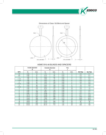
ORIGINAL INSTRUCTIONENGLISH2. SAFETY2.1 SAFETY INSTRUCTIONSA Nose piece/front sleeveD Safety valveB Mandrel collectorE Air supply closing valveC TriggerF Air connection2.2 PERSONS Use safety goggles. This also applies to persons in the immediate surroundings.Use hearing protection when the sound level exceeds 85 dB(A).Use safety gloves, certain blind rivets can become very warm at some places.Keep your fingers away from the front when connecting the compressed air.Do not look straight into the tool (front and rear).Never direct the tool at persons.5
ENGLISH2.3 WORK ENVIRONMENT Keep the work environment clean and neat.Use dry, filtered and with anti-corrosive oil lubricated air. If notavailable, put 0.1 ml (approximately 5 drops) of anti-corrosivelubricating oil in air connection of tool three times each operatingday.Work in a frost-free environment.The connection to the tools is G1/4“.A connection nipple has not been included.Provide an appropriate solution yourself. Set a constant air pressure to 5 - 7 bars (maximum 7 bars).2.4 TOOLSNever use the tools- when the nose piece/front sleeve (A) is missing;- when the mandrel collector (B) has not been positionedCheck the tools for damage before connecting the air pressure.Keep the tools in an optimum condition.Switch off the closing valve (C) when the tools are not used.Make sure that the flexible connection hose (D) is not pressurisedwhen disconnecting.Do not modify the tools in any way.Only use the device for appropriate purposes. 2.5 DATE CODEThis is the place of the Date Code (A) of the tools.2.6 TYPE IDENTIFICATIONThis is the place of the type identification (B) of the tools.6ORIGINAL INSTRUCTION
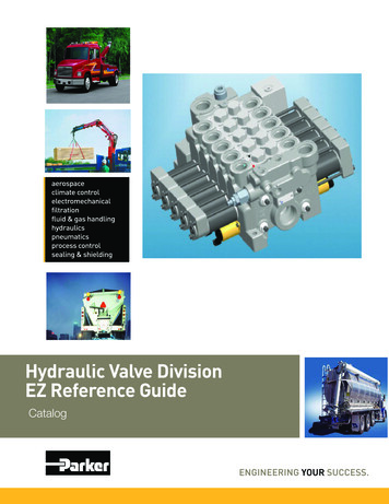
ORIGINAL INSTRUCTIONENGLISH3. MAIN COMPONENTS3.1 COMPONENTSA Nose pieces**B Front sleeveC Hydraulic bodyD Mandrel collectorE TriggerF Pneumatic bodyG Safety valveH Air connectionJ ManualK CE and guarantee formL CD with manual in various languages3.2 NOSE PIECESThe delivered box contains various nose pieces.****EZM 1000: 3.0 – 5.0 mmEZM 2000: 4.0 – 6.4 mm7
ENGLISHORIGINAL INSTRUCTION4. OPERATION4.1 CONTROLSA BracketD TriggerB Mandrel collectorE 360 Revolvable air supply unitC Air outletF Air supply closing valve8
ORIGINAL INSTRUCTIONENGLISH4.2 MANDREL COLLECTORThe purpose of the mandrel collector is to collect the restmandrel. The collector can be placed in three positions.A Position/remove.B Lock – without extraction. Tilting the tools will make sure thatthe mandrel will end up in the collector.C Lock – with extraction. The rest mandrel is automaticallyblown into the collector.4.3 REVOLVABLE AIR OUTLETThe escaping airflow can be set using the revolvable air outlet (A)such, that people experience a minimum of discomfort duringwork.Do not remove this air outlet from the mandrel collector.4.4 360 REVOLVABLE AIR SUPPLY UNITWhen the air hose (A) causes discomfort during work, turn offclosing valve (B). After this the 360º revolvable unit (C) can beturned into any required position.9
ENGLISHORIGINAL INSTRUCTION5. USEPosition the nipple (G1/4“).Position the mandrel collector.Set the mandrel collector (see 4.2).Set the revolvable air outlet (see 4.3).Mount the correct nose piece.Set the correct air pressure (see 2.3).10
ORIGINAL INSTRUCTIONENGLISHTurn on the closing valve.Position the blind rivet.Position the tools.Press the trigger.Turn off the closing valve.Empty the mandrel collector after use.11
ENGLISH6. MAINTENANCEUse safety gogglesUse hearing protectionUse safety gloves6.1 FRONT SLEEVETurn off the closing valve (A) and disconnect the air supply (B).- Remove the front sleeve (A).- Pay attention to the o-ring (B).Clean the inside using an air blow gun.12ORIGINAL INSTRUCTION
ORIGINAL INSTRUCTIONENGLISH6.2 CLAMPING JAWSRemove the front sleeve, see 6.1.Remove the clamping sleeve (A) and the Teflon ring (B), the 2clamping jaws (C) and the jaw pusher (D).Clean the clamping jaws and the jaw pusher or replace them.Make sure that the spanner does not slip offthe locking nut (E). This may damage thehydraulic piston rod (F).Mounting is done in reverse order.When mounting, lightly spray the inside ofthe clamping sleeve with Teflon spray.Make sure that the locking nut is positionedbetween 19-20 mm from the hydraulic body.13
ENGLISHORIGINAL INSTRUCTION7. TROUBLE SHOOTINGProblemCauseCorrective actionThe tool does not workThe tool has not been connected tothe air connectionConnect the tool to the air connectionThe air supply closing valve is stillclosedOpen the air supply closing valveThere is insufficient air pressureUse the correct air pressure 5-7 barAir is coming out of the safetyvalveThe air pressure is too highUse the correct air pressure 5-7 barThere is no or insufficientextractionThe extraction has not been turned onCheck the position of the mandrel collectorThere is insufficient air pressureUse the correct air pressure 5-7 barThe mandrel collector is fullEmpty the mandrel collectorThe tool is blocked by rest mandrelsRemove the rest mandrelThe trigger does not workThere is insufficient air pressureUse the correct air pressure 5-7 barThe blind rivet cannot beplaced into the nose pieceThe incorrect nose piece has beenmountedMount the correct nose pieceThe tool is blocked by rest mandrelsRemove the rest mandrelContaminated or worn clamping jawsClear or replace the clamping jawsThere is insufficient air pressureUse the correct air pressureThe capacity of the tool has beenexceededUse the correct toolThe incorrect nose piece has beenmountedMount the correct nose pieceThe tool is blocked by rest mandrelsRemove the rest mandrelThe blind rivet is not setcorrectlyThe rest mandrel does notrelease from the nose pieceDuring setting the rivetmandrel does not breakThere is insufficient air pressureUse the correct air pressureThe capacity of the tool has beenexceededUse the correct toolThe rest mandrel is notextracted into the mandrelcollectorThe incorrect nose piece has beenmountedMount the correct nose pieceThe tool is blocked by rest mandrelsRemove the rest mandrelThe mandrel collector is fullEmpty the mandrel collectorThe tool is still under air pressureClose the air supply closing valve anddepressurize the tool by turning on theextraction or by operating the triggerThe air supply unit cannot beturned 360 The tool does not perform wellconsistently14Contact a service centre
ORIGINAL INSTRUCTIONENGLISH8. TECHNICAL DATAEZM 1000EZM 2000H264 mm275 mmL272 mm272 mmøD102 mm125 mmP70 mm70 mmøS23 mm23 mmWeight1,25 kg1,65 kgAir pressure5-7 bars5-7 barsPull force (6 bars)7.3 kN12.5 kNAir consumption (per stroke)1.5 l2.0 lStroke17 mm21 mmCapacity (standard blind rivet)ø 3.0 – 5.0 mm (stainless steel)ø 4.0 – 6.4 mm (stainless steel)15
ENGLISHORIGINAL INSTRUCTION9. EC DECLARATION OF CONFORMITYWe,Rivet Factory Group s. r. o.Lannova 2061/8110 00 Praha 1, Nové Město,declare under our sole responsibility that the product:Description:HYDRO-PNEUMATIC RIVETING TOOLModel:EZM1000, EZM2000To which this declaration relates is in conformity with the following harmonized standardsSafety:Machinery Directive:ČSN EN ISO 11148-1:2015Technical documentation is compiled in accordance with Annex 1, section 1.7.4.1, of the following Directive: 2006/42/ECThe Machinery Directive (Statutory Instruments 2008 No 1597 - The Supply of Machinery (Safety) Regulations).The undersigned makes this declaration on behalf of Rivet Factory GroupBc. Ondřej Slezák, CEORivet Factory Group s. r. o.Lannova 2061/8110 00 Praha 1, Nové MěstoPlace of Issue:Drtinovo náměstí 171, 547 01 Náchod, Czech republicDate of Issue:11. 6. 2021The undersigned is responsible for compilation of the technical file for products sold in the European Union and makes thisdeclaration on behalf of STANLEY Engineered Fastening.Matthias AppelTeam Leader Technical DocumentationStanley Engineered Fastening, Tucker GmbH, Max-Eyth-Str.1,35394 Gießen, GermanyThis machinery is in conformity withMachinery Directive 2006/42/EC16
ORIGINAL INSTRUCTIONENGLISH10. UK DECLARATION OF CONFORMITYWe,Rivet Factory Group s. r. o.Lannova 2061/8110 00 Praha 1, Nové Městodeclare under our sole responsibility that the product:Description:HYDRO-PNEUMATIC RIVETING TOOLModel:EZM1000, EZM2000to which this declaration relates is in conformity with the following designated standards:Safety:The Supply of Machinery (Safety) Regulations 2008 S.I. 2008/1597 (as amended):Designated StandardsČSN EN ISO 11148-1:2015Technical documentation is compiled in accordance with the Supply of Machinery (Safety) Regulations 2008, S.I. 2008/1597(as amended).The undersigned makes this declaration on behalf of Rivet Factory GroupBc. Ondřej Slezák, CEORivet Factory Group s. r. o.Lannova 2061/8110 00 Praha 1, Nové MěstoPlace of Issue:Drtinovo náměstí 171, 547 01 Náchod, Czech republicDate of Issue:11. 6. 2021The undersigned is responsible for compilation of the technical file for products sold in the United Kingdom and makes thisdeclaration on behalf of Stanley Engineered Fastening.A. K. SeewrajDirector of Engineering, UKAvdel UK Limited, Stanley House, Works Road, Letchworth Garden City, Hertfordshire,SG6 1JY UNITED KINGDOMThis machinery is in conformity withSupply of Machinery (Safety) Regulations 2008,S.I. 2008/1597 (as amended)17
ENGLISH18ORIGINAL INSTRUCTION
ПРЕВОД ОТ ОРИГИНАЛНИТЕ ИНСТРУКЦИИБЪЛГАРСКИ 2021 STANLEY Black & DeckerВсички права запазени.Предоставената информация не може да бъде възпроизвеждана и/или оповестена по никакъв начин и чрез никаквисредства (електронно или механично) без предварително изрично и писмено разрешение от STANLEY EngineeredFastening. Предоставената информация се основава на данните, известни в момента на пускането на пазара натози продукт. STANLEY Engineered Fastening провежда политика на постоянно усъвършенстване на продукта иследователно продуктите могат да бъдат променяни. Предоставената информация е приложима за продукта, кактосе предлага от STANLEY Engineered Fastening. Ето защо, STANLEY Engineered Fastening не може да носи отговорност завреди, причинени от отклонения от първоначалните спецификации на продукта.Наличната информация е съставена много внимателно. Въпреки това, STANLEY Engineered Fastening ня
Hydraulic/Pneumatic Blind Riveting Tools . STANLEY Engineered Fastening STANLEY House, Works Road Letchworth Garden City Hertfordshire, United Kingdom SG6 1JY Tel: 44 1582 900 000 Fax: 44 1582 900 001 Holding your world together .