Transcription
Automotive Innovation (2021) 8-yCathode Design for Proton Exchange Membrane Fuel Cellsin Automotive ApplicationsHaojie Wang1 · Ruiqing Wang2 · Sheng Sui2 · Tai Sun3 · Yichang Yan4 · Shangfeng Du4Received: 21 November 2020 / Accepted: 22 March 2021 / Published online: 21 April 2021 The Author(s) 2021AbstractAn advanced cathode design can improve the power performance and durability of proton exchange membrane fuel cells(PEMFCs), thus reducing the stack cost of fuel cell vehicles (FCVs). Recent studies on highly active Pt alloy catalysts, shortside-chain polyfluorinated sulfonic acid (PFSA) ionomer and 3D-ordered electrodes have imparted PEMFCs with boostedpower density. To achieve the compacted stack target of 6 kW/L or above for the wide commercialization of FCVs, developingavailable cathodes for high-power-density operation is critical for the PEMFC. However, current developments still remainextremely challenging with respect to highly active and stable catalysts in practical operation, controlled distribution ofionomer on the catalyst surface for reducing catalyst poisoning and oxygen penetration losses and 3D (three-dimensional)ordered catalyst layers with low Knudsen diffusion losses of oxygen molecular. This review paper focuses on impacts ofthe cathode development on automotive fuel cell systems and concludes design directions to provide the greatest benefit.Keywords Fuel cell vehicle (FCV) · Proton exchange membrane fuel cell (PEMFC) · Cathode · Mass transport · IonomerAbbreviationsCCL Cathode catalyst layerCL Catalyst layerCNT Carbon nanotubeECSA Electrochemical surface areaEW Equivalent weightFCV Fuel cell vehicleGDE Gas diffusion electrodeGDL Gas diffusion layerLSC Long-side chainMEA Membrane electrode assemblyMPL Microporous layer* Sheng Suissui@sjtu.edu.cn* Shangfeng Dus.du@bham.ac.uk1School of Mechanical and Power Engineering, East ChinaUniversity of Science and Technology, Shanghai 200237,China2Institute of Fuel Cells, Shanghai Jiao Tong University,Shanghai 200240, China3Research Institute of Rare Metals, Guangdong Academyof Sciences, Guangzhou 510650, Guangdong, China4School of Chemical Engineering, University of Birmingham,Birmingham B15 2TT, UK13Vol:.(1234567890)ORR Oxygen reduction reactionPBI PolybenzimidazolePEG Polyethylene glycolPEM Proton exchange membranePEMFC Proton exchange membrane fuel cellPFSA Polyfluorinated sulfonic acidPGM Platinum group metalPTFE PolytetrafluoroethyleneRDE Rotating disk electrodeTPB Triple-phase boundary1 IntroductionFuel cells convert chemical energy from the reaction of afuel (hydrogen or hydrocarbons) and an oxidant (i.e., oxygen) directly into electricity with high efficiency and environmental benefits (zero or low emission). The fuel celltechnology has been successfully used in many applications, such as stationary power generation for electricitygrid, automobile vehicles and portable power devices [1].Among all types of fuel cells, PEMFC is one of the mostpromising alternatives to internal combustion engines (ICEs)as power sources for transportation because PEMFCs operate at close to ambient conditions, enabling fast start-up andshut-down [2]. Since the first use for the Gemini spacecraft
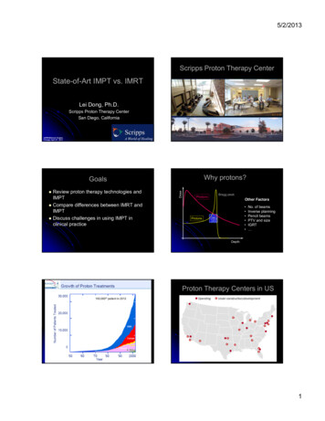
Cathode Design for Proton Exchange Membrane Fuel Cells in Automotive Applications by General Electric (GE) in the 1960s, the PEMFC technology goes through a long way to access commercialization [3]. Japan, South Korea, the US, European nations andChina have successively formulated visions and roadmapsof hydrogen and fuel cells, and lead commercialization offuel cell electric vehicles (FCVs). Toyota launched the firstgeneration commercial FCV MIRAI in 2014 and the secondcopy in 2019. Hyundai also revealed their new hydrogenfuel cell SUV Nexo in 2018. However, to compete with ICEvehicles, PEMFCs in FCVs are challenging in the fields ofcost reduction and performance improvement, particularlyin the ability to achieve high-power-density operation at highenergy efficiency [4].Figure 1 shows the schematic representation of a PEMFC.The core of the PEMFC is a membrane electrode assembly (MEA), which includes the polymer electrolyte membrane (PEM), catalyst layers (CLs) and gas diffusion layers(GDLs). The MEA is the place for electrochemical reactionsincluding hydrogen oxidation reaction (HOR) at the anodeand oxygen reduction reaction (ORR) at the cathode, andalso for transfer processes involving multiphase transport,i.e., fuel and oxidant gases from GDLs to CLs, the protonfrom the anode to the cathode through the PEM and transport of water produced in the cathode [5]. Many studies onPEMFCs for vehicle applications now focus on the R&D ofcost-effective MEAs with low platinum loading and highdurability under practical operating conditions [6, 7].In PEMFCs, the sluggish ORR at the cathode is about5–6 magnitudes slower than the hydrogen oxidation reaction HOR at the anode, thus causing a large kinetic lossthat limits the fuel cell power performance. Therefore, morecatalysts are required for the cathode than that for the anodeto boost the ORR rate during fuel cell operation. Pt is commonly used at both electrodes and it alone is accountablefor more than 40% of the MEA cost in PEMFCs, delayingmass commercialization of this technology. Lots of effortshave been made to improve the catalyst activity and reducethe Pt loading [3]. The first PEMFC unit used in the GeminiFig. 1 Flux balance overviews in a simplified PEMFC model [8]145aircraft contained a very high catalyst loading (4 mgPt/cm2)of unsupported Pt black bound by polytetrafluoroethylene(PTFE) within the electrodes [9]. An important breakthrough in the PEMFC development was achieved by LosAlamos National Laboratory in the 1980s, when the catalyst utilization was significantly improved and the Pt loadingwas reduced to less than 0.4 mg/cm2 as mostly used today.Those were achieved through extending the triple-phaseboundary (TPB) zone in the catalyst layer by introducingproton-conducting ionomer (such as Nafion) and the carbon-supported platinum (Pt/C) catalyst into the electrodes.Since then, further progresses have been achieved on theimprovement of MEAs and the related technologies [10].For example, Chong et al. [11] prepared highly active ORRcatalysts by growing PtCo alloy nanoparticles on CoNCsubstrate derived from zeolitic imidazolate frameworks.With an ultralow cathode Pt loading of 0.033 mgPt/cm2, theMEA achieved a power density of more than 1 W/cm2 in H2-air fuel cell test under 2 barabs of absolute pressure. WithN-modified carbon as support for Pt nanoparticle catalysts,Ott et al. [12] designed cathodes showing a power densityof 1.39 W/cm2 at a cathode Pt loading of 0.11 mgPt/cm2(tested at 80 C with fully humidified H 2/air at a pressureof 230 kPaabs).Despite tremendous progress achieved with the PEMFCdevelopment, there are still many challenges with PEMFCsfor their extensive commercialization as FCVs, especiallyrelated to the exorbitant cost, low-power performance andpoor durability. The cost of an FCV mainly comes frommanufacturing and materials. Manufacturing issues, a bigpart contributing to the current high fuel cell system cost,are amenable to major reduction through economies of scale.Whereas precious metal material costs with the electrocatalysts would not benefit from the economy of scale and evenincreases at high FCV market penetration [5]. A potentialstrategy to address this challenge is the development of highpower-performance electrodes with an ultralow Pt loadingor Pt-free through the novel catalyst and electrode structuredesign. Another problem is, along with the development ofPEMFCs operating at a large current density (e.g. 2.5 A/cm2), the cathode catalyst layer undergoes a high water saturation level (i.e., flooding conditions). This thus reducesoxygen mass transport to reaction sites of the catalyst finallyresulting in poor fuel cell power performance [13]. Accordingly, various technologies, including 3D mesh flow fieldplates [14, 15], ordered structure electrodes [16] and hydrophobic GDLs [17], have been investigated to overcome thewater management issues.In this review paper, an overview of the R&D of PEMFCs with a focus on the cathode catalyst layer is first presented, according to a viewpoint from micro-scale TPB tomacro-scale catalyst layer design. Then, research advancements about promoting intrinsic cathodic ORR activities13
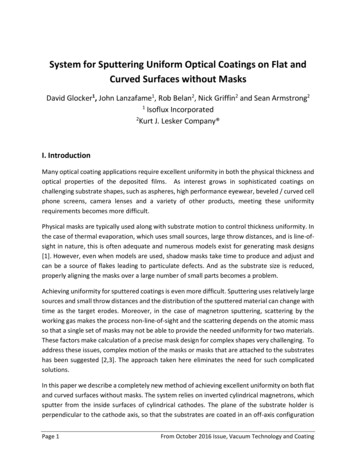
146H. Wang et al.in PEMFCs are briefly described. The research efforts onimproving mass transport of oxygen and water in the cathodecatalyst layer are discussed in detail. Publications reportingMEAs with high-power-density operation are also reviewed.At last, an outlook of the catalyst electrode development forhigh-power-density operation PEMFCs is given.2 Promoting Intrinsic Kinetic Performanceof Electrodes2.1 Triple‑Phase Boundary (TPB)The catalyst layer in fuel cell operation provides continuous channels for electrochemical reactants including protons, electrons and gas (and water in the cathode) [18, 19].As shown in Fig. 2, the interface (red hollow circle)amongthe catalyst for conducting electrons, electrolyte phase forconducting protons and pores for transporting gases and/or water is named as TPB. This concept has been generallyused in the study of electrode structure to explain the complex interaction within the CL [20, 21].The electrochemical reaction within the CL is multiphase.Typically, the catalyst layer is a thin film composed of carbon-supported highly dispersed Pt catalyst nanoparticlesand Nafion ionomer additive [22]. The microstructure andcomposition of the CL have a great influence on its powerperformance [20, 23–26]. Therefore, many research effortshave been made to optimize the TPB properties within theCL, which can be divided into three strategies: (i) adoptinghighly active catalysts to promote the intrinsic ORR activity, (ii) introducing novel ionomers to enhance conductivityand (iii) improving catalyst/ionomer interface to extend TPBzones [27, 28].2.2 ORR CatalystsTo create efficient triple-phase interfaces to catalyze theORR, highly active catalysts are essential. In view of theelements, the catalysts are usually divided into two categories as platinum group metal (PGM) and platinum groupmetal-free (PGM-free)-based materials. Among all theexploited catalysts, pure Pt or Pt-based catalysts are still thebest option in terms of automotive applications. The progress and achievements of ORR catalysts in recent decadeshave been frequently reviewed by researchers based on theiractivities and durability [3, 29, 30].2.2.1 Pt‑based CatalystsPt-based catalysts, including pure platinum, platinum alloysand core–shell platinum structures, are the dominant choicesfor ORR [31–33]. For single-crystal Pt catalysts, controlling13Fig. 2 Schematic illustration of triple-phase boundary in the PEMFCcathodefacets via surface atom rearrangement can tune their catalytic activities [34] because of the structure sensitivity of theORR to different Pt crystal surfaces [35].Alloying to form Pt-based bimetallic and trimetallic electrocatalysts is another effective way to improving ORR activity and stability, which is attributed to a shift of the d-bandcentre caused by electronic structure change on alloy surfaces [36]. Pt monolayer (ML) catalysts, an ideal core–shellstructure, can offer a distinctively reduced Pt loading whilemaintaining considerable possibility for enhancing theiractivity and stability [37].PtNi alloy system has been proved to show an excellentperformance toward ORR. Stamenkovic et al. [38] demonstrated that P t3Ni (111) surface possessed 90-fold higheractivity toward ORR than Pt/C nanoparticle catalysts forPEMFCs. Besides nanoparticles, many shape-controllednanostructures were also reported. Chen and co-workers[39] reported P t3Ni nanoframe catalysts exhibiting a factorof 36 and 22 fold enhancement in mass activity and specificactivity, respectively, relative to 5 nm Pt/C catalysts (TKK)in half-cell electrochemical measurement using the rotating disk electrode (RDE) technique in a liquid electrolyte.Another breakthrough is the achievement of ultrafine jagged Pt nanowires prepared through fully leaching Ni fromPtNi nanowires [40]. The catalyst demonstrated the highestrecorded mass activity of 13.6 A/mgPt2 in the RDE measurement. However, these new shape-controlled catalystsare still in development and a bit distant from the practicalapplications in PEMFCs for FCVs because of the high difficulties in their scale-up preparation. PtCo alloy catalystshave been demonstrated with similar great ORR activities asPtNi, and they are also the only advanced ORR catalyst thathas been successfully used in mass-produced FCVs, i.e., inToyota Mirai [41]. Compared with other PtM (M representsa transition metal) materials and the widely used Pt/C nanoparticles, PtCo alloy catalysts can provide a better balance
Cathode Design for Proton Exchange Membrane Fuel Cells in Automotive Applications between the activity and durability. In an H 2/O2 MEA testwith a cathode Pt loading of 0.1 mg/cm2, PtCo/C catalystdemonstrated a high voltage of 0.650 V at 1.5 A/cm2, 40 mVhigher than that of 3 nm Pt catalysts supported on Vulcancarbon (20 wt% Pt) [42]. Accelerated stress test (AST) inthe MEAs also indicated better stability, and this was furtherenhanced by annealing at a high temperature (e.g., 600 C)to improve the retention of Co and further suppressed Ptdissolution/re-deposition in fuel cell operation. An investigation, conducting on the durability of PEMFC cathodes madeof PtCo alloy nanoparticle catalysts with different initial Cocontents (34, 20 and 15 mol%, respectively) revealed thateven with significant (27–50%) Co loss, the specific activityof all PtCo alloy catalysts toward ORR remained higher than1000 μA/cm2Pt, exceeding 650 μA/cm2Pt of pure Pt nanoparticles [43]. With commercialized fuel cells in the 2015Toyota Mirai, MEAs with PtCo catalysts also reached ca.1.8 A/cm2 at 0.67 V (Pt loading at both electrodes 0.33 mg/cm2. Tested in 50 cm2 H2/air PEMFCs at 94 C with 65/65%RH, 250/250 kPaabs and stoichiometries of 1.5/2 [44].)Depositing or forming a thin Pt-based shell (one or several atomic layers) upon the other metal core (Pd, Ru, etc.)is a core–shell structure to improve Pt utilization and toachieve remarkable activity and stability. Chung et al. [45]demonstrated that the ORR of such core–shell nanoparticles was largely affected by their subsurface compositionrather than the bulk composition. Sasaki et al. [37] reviewedthe catalyst achievement in Pt monolayer on palladium (Pd)nanoparticles for the ORR and described the mechanismsthat rationalized their high activity and stability. Theyrecently demonstrated that the ORR activity and stabilityof the catalysts could be further improved with some novelnanostructured cores by optimizing their surface orientation,composition and morphology [46, 47].2.2.2 Platinum Group Metal‑Free CatalystsPGM-free catalysts, including transition metal-based andnon-metallic catalysts, are potential candidates to furtherreduce the cost of PEMFCs in the future. The most promising PGM-free catalysts toward ORR for PEMFC applications are carbonaceous materials doped with nitrogen andone (or more) active 3D-period transition metals (e.g., Fe,Co, Mn, Ni) [48]. The breakthroughs of Fe–N–C catalystshave been very recently reviewed by Wang et al. [49] withreference to DOE (Department of Energy) standards andtargets. However, despite the progress in recent years, theelectrocatalytic activity and stability of PGM-free catalystsare still not expected to meet the practical demands in ashort time [50].In 2006, a breakthrough on PGM-free FeNC catalysts wasachieved by Dodelet et al. [51] who found the crucial roleof micropores on carbon substrates for hosting the atomic147active sites. Zelenay and co-workers [52] thus reported aconsiderable activity of 0.016 A/cm2 at 0.9 ViR-free underthe DOE testing protocol, using a hierarchical porous FeNCcatalyst ((CM PANI)–Fe–C). Recently, many researchershave reported on the three-dimensional (3D) architectureof PGM-free catalysts to enhance mass transfer propertiesand catalyst utilization ratio to achieve reasonable powerperformance in PEMFCs. Li and co-workers [53] reportedcontrolled 3D fibrous FeNC cathodes engineered via a facileelectrospinning approach. The cathode achieved 0.3 A/cm2at 0.6 V in H2/air fuel cell test. Wu and co-workers [54]reported a novel imidazole-based ionic liquid and used itto prepare an N and S co-doped metal-free catalyst with3D-ordered microstructures. Wang et al. [55] reported anewly designed F eOx@graphitic carbon core–shell structured nanoparticles implanted in an N-doped carbon matrix.With ordered and mesoporous structure, the FeOx@GCcathode with a catalyst loading of 3 mg/cm2 recorded aspecific power density of 350 W/g1 in H2/O2 PEMFC test.In consideration of improving the catalyst electrode durability, hybrid Pt/FeNC with an ultralow loading of Pt havebeen demonstrated and synergy effects were reported [56,57]. STEM (Scanning transmission electron microscope)analysis revealed a stabilization of the Fe-oxide by subsurface Pt (111) and they attributed the enhanced stability andORR activity to the electron-tunnelling effect from Pt (111)through the ultrathin Fe-oxide shell.In 2017, Ballard Power Systems announced the commercialization of the world’s first PEMFC product to utilize aPGM-free catalyst at the cathode (FCgen-micro) [58, 59].However, the PGM-free catalyst is not widely used now.2.3 Extending TPB Zones by IonomersIntroducing proton-conducting ionomer into electrodesbrought about a great breakthrough in the PEMFC development in the 1980s, which greatly extended the TPB zoneand improved electrode power performance by boostingthe Pt utilization. In the CL, the ionomers act as: (i) protonconductors to expand the electrochemically active regioninto the bulk catalyst layer, (ii) binding materials to impartmechanical stability and (iii) hydrophilic agents to helpretain moisture and prevent membrane dehydration [60]. Thedistribution and content of ionomer can directly influencethe protonic and electronic conductivity of the CL. Particularly, when PEMFC is operating at a large current densityexceeding 1.5 A/cm2, the ionomer distribution becomesmore important because of the mass transport of H and O2through the ionomer film on the catalyst surface.13
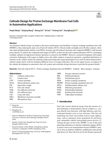
1482.3.1 Perfluorinated Sulfonic‑Acid (PFSA) IonomerConventionally, Nafion ionomer is mixed with Pt/C to createPt/ionomer/C TPB. Nafion, a trademark of DuPont company,is a perfluorinated sulfonic-acid (PFSA) ionic polymer containing a highly hydrophobic PTFE backbone and a stronghydrophilic sulfonic acid side chain. PFSA ionomers aremembers of a class of ion-conductive polymers known fortheir remarkable ionic conductivity and their chemical andmechanical stability. The characteristics of phase separationand proton transport of PFSA ionomers are determined bytheir chemical structure and composition [61]. Many PFSAionomers have been developed, and Fig. 3 shows severalcommercial types with their key chemical structural parameters. PFSA ionomers are usually categorized according totheir side-chain length or equivalent weight (EW). For example, Aquivion (formerly Dow SSC) PFSAs are commonlyclassified as short-side-chain (SSC) PFSAs, while Nafion isconsidered as a long-side-chain (LSC) PFSA. The conductivity of PFSA ionomers increases as the EW is lowered.Traditionally, PEMFCs utilize LSC PFSA ionomer (i.e.,Nafion) and many studies have been reported on the structure-power performance relationships of Nafion-based catalyst layers. The investigation shows that, with the increasein the ionomer loading, the ionic conduction efficiencyincreases, while the electronic conduction efficiency diminishes, both in an exponential fashion [62]. For an ultralowcatalyst loading electrode operating at a large current density, the requirements for proton-conducting and mass transport are very high, thus optimal use of ionomer is of highimportance to balance the porosity, proton and water transport in the cathode CL.The use of SSC ionomer in the catalyst layer has beendemonstrated with some advantages. Compared with theFig. 3 General chemical formula for commercial PFSA ionomers,shown with key chemical structural parameters [61]13H. Wang et al.LSC ionomer, the low EW SSC ionomer has more sulfonicgroups that can improve its proton conductivity, and theionomer distribution and coverage on the catalyst surface inthe CL [63]. Garsany et al. [64] found that the SSC ionomerimparted low proton transport resistances, reducing chargetransfer resistance within the cathode at near 0.60 V andmass transport resistance at 0.40 V. The improved electrodeperformance was attributed to the superior proton conductivity of the SSC ionomer and higher micropore volume. Thelatter can be more effective for evaporating water to the gasphase and improve the availability of both catalyst sites forcharge transfer and mesopores for gas transport.2.3.2 Other Proton ConductorsPFSA ionomers have several drawbacks, and the mostimpressive ones are their high synthesis cost because of thecomplex fluorine chemistry and requirement of high humidity resulting in a mandatory low fuel cell operating temperature [65]. Several solutions have been developed with lowfluorinated or even no-fluorinated SSC ionomer polymers tosubstitute PFSA ionomers.A low-fluorinated ionomer is beneficial to reduce cost.Ebenezer et al. [66] used low-fluorinated and low-cost crosslinked PVA/SSA ionic polymer as hydrocarbon ionomer toprepare CLs. They identified that the performance of thisionomer was as good as Nafion in the anode catalyst layerand the MEA was less sensitive to the relative humidity ofreactant gases. Yang et al. [67] reported a bottom-up designof Pt electrocatalysts with a homogeneous Nafion-freeionomer layer, in which Pt nanoparticles were deposited onCNTs after sequentially wrapping with polybenzimidazole(PBI) and protonic conductive end-capped hyperbranchedsulfonated macromolecules (E-HBM) (CNT/PBI/E-HBM/Pt). The base–acid interaction between PBI and E‐HBMenabled homogeneous coating of E‐HBM on CNTs, leadingto improved Pt stability and electrode durability. The MEAfabricated from the CNT/PBI/E-HBM/Pt cathode showed ahigher power density of 704 Mw/cm2, compared to 603 Mw/cm2 with Nafion ionomer.Dru et al. [68] proposed a universal nonfluorinated solution to build the catalyst layer. The fluorine-free ionomersodium polystyrenesulfonate (PSSNa) was grafted directlyat the surface of carbon-supported Pt nanoparticles for thetransposition of the TPB at the molecular level. Figure 4shows the synthesis process of the Pt-PSSNa/C nanocomposite material. The results show that both the chain lengthand the number of grafted polymers played a big role in thecatalyst activities and stability in fuel cell operation. A lowgrafting density and high degree polymerization led to betterperformance, exhibited the same power density but betterdurability than that with Nafion ionomer (60 cf. 90 μV h–1)in H2/O2 PEMFC test.
Cathode Design for Proton Exchange Membrane Fuel Cells in Automotive Applications Another strategy recently reported combines ionic liquids(ILs) with Nafion ionomer to extend proton-conducting network in CLs. Some ILs possess excellent oxygen solubilityand diffusivity, although not as good as Nafion ionomer,they can penetrate the small pores that cannot be reachedby the large ionomer cluster thus enhancing catalyst utilization ratio. Li et al. [69] introduced a sulfonated poly(ionicliquid) block copolymer (SPILBCP) as an additive to Nafionionomer in the catalyst layer. From an electrode structurepoint of view illustrated in Fig. 5, LSC Nafion ionomerhelps bridging vacancies between isolated SPILBCP aggregates under both high and low relative humidity, forminghighly connected ionomer networks and facilitating protontransport in the catalyst layer, increasing Pt utilization. Theuse of superhydrophobic ILs can further help repel the produced water and reduce the surface oxidation of catalysts.For examples, ILs include [MTBD] [beti] (7‐methyl‐1,5,7‐triazabicyclo [4.4.0]dec‐5‐ene bis(perfluoroethylsulfonyl)149imide), [C4C1im] [NTf2] lfonyl)imide) and [BMIM] [NTf2](1-butyl-3-methylimidazolium bis(trifluoromethylsulfonyl)imide) have been used to modify Pt-based PtNi/C and Pt/C,and PGM-free ZnCoNC catalysts for PEMFC application[70–72]. Importantly, ILs presenting at the catalyst interfacecan act to prevent the specific adsorption of sulfonate groupsof Nafion on Pt surfaces, negating the detrimental impactof the ionomer on reaction rates, specifically for ORR, thusimproving PEMFC high current density performance [73].Improved power performance was successfully demonstratedin either H2/O2 or H 2/air MEA test. However, the durabilityof this approach is still not clear in long-term fuel cell operation, in particular considering the severe higher operatingtemperature compared to the electrochemical measurementin a liquid electrolyte where the outstanding stability of thisIL modification has been shown.Fig. 4 Pt-PSSNa/C nanocomposite material synthesis process [68]Fig. 5 Proposed microstructure of 0.6SPILBCP:C and0.3SPILBCP:C 0.3Nafion:Celectrodes depicting the effectof ionomer distribution on Ptutilization under dry and wetoperating conditions [69]13
1502.4 Improving Ionomer/Catalyst InterfaceIn PEMFC catalyst layers, ionomers are found as nanometer-thick “thin films” binding the catalyst particles together,facilitating proton transport through the layer and gas/watertransport to and from the catalytic sites, respectively [61].Homogeneous distribution of ionomer on catalyst surface is essential to achieve high-power performance and sustained electrode stability, i.e., high ORR kinetics and excellent mass transport properties. Typically, the catalyst layeris fabricated starting from catalyst ink, which is preparedby mixing carbon-supported Pt nanoparticle catalysts (i.e.,Pt/C), Nafion ionomer, isopropyl alcohol, and water [74].After thoroughly mixing the catalyst ink to ensure a homogenous mixture, it is sprayed or coated onto the microporouslayer of a GDL for the case of the gas diffusion electrode(GDE), or the membrane for the case of the catalyst coatedmembrane (CCM) [75]. In improving the ionomer/catalystinterface, the catalyst support structure and surface properties [12, 63], ionomer/catalyst ratio [76] and catalyst inkdispersing methodology [77] all show great influence on theelectrode power performance.The catalyst/ionomer interfacial structure is largely determined by the interaction between Pt and the ionomer sidechains, and the density of ionomers is higher in areas ofthe catalyst surface containing Pt because of the better wettability of Pt surface than that of the carbon support [63].However, the strong adsorption of the sulfonate group ofthe PFSA ionomer is poison for the Pt surface and reducesthe catalyst activity during fuel cell operation. Yamada et al.[78] used dopamine (DA) to protect the Pt catalyst surfacefrom poisoning. The coverage of the adsorbed sulfonatesfrom the ionomer on the Pt surface was decreased with theincreasing DA amount. Improved mass activity and durability were achieved. However, this method cannot addressthe oxygen transport issue at the interface between Pt andionomer. The power performance at a high current densityoperation was deteriorated by the modification. Zhou et al.[79] have explored a thin porous layer derived from Nafionformed on the surface of Pt/C catalyst to create a shell toreduce the ionomer poisoning and improve the oxygenaccessibility. The experimental results demonstrated a verythin coating that helped to separate the Nafion ionomer andPt particles in the catalysts exhibiting enhanced fuel cellperformance.Breakthrough in boosting the PEMFC power performancehas recently been achieved through tuning structure and surface properties of catalyst support to improve the interactionbetween ionomer and catalysts. Yarlagadda et al. [44] demonstrated that porous carbons with a preferred pore size of4–7 nm endowed catalysts with both excellent ORR activities and transport properties (Fig. 6). Catalysts supported onsolid carbon have good transport properties, but are easily13H. Wang et al.poisoned by the ionomer. In contrast, for catalysts supportedon porous carbon, the interior catalyst particles within poreshave limited access to protons and reactant gases. And, thiseffect will become more prominent for an electrode withan ultralow Pt loading operated at a large current density.Compared to solid Vulcan and porous Ketjenblack support,PtCo supported on porous carbon with access pores showeda boosted power performance of 14.3 kW/gPGM with a cathode Pt loading of 0.063 mgPt/cm2 (tested at 94 C with a50 cm2 MEA under H 2/air at 65/65% RH, 250/250 kPaabs andstoichiometries of 1.5/2 at the anode/cathode, respectively).Recent achievements revealed that the ionomer distributionon Pt/C surface can be tailored by modifying carbon support surface. Orfanidi et al. [80] functionalized carbon support with –NHx groups. The coulombic interaction between–NHx groups and negatively charged –SO3 of the ionomer side-chains promoted the homogeneous distribution ofthe ionomer on Pt/C catalyst surface, although the stabilityof –NHx groups to sustain the suppression of local oxygentransport losses is still an issue. As an advancement, N-modified ketjenblack has been recently studied by Ott et al. [12]The surface N-modification of carbon support with tailoredporosity imparted controlled deposition of Pt nanoparticlesin or close to carbon pores, and also a uniform coverage ofionomer on the support surface. This also led to a lower
fuel cell electric vehicles (FCVs). Toyota launched the rst-generation commercial FCV MIRAI in 2014 and the second copy in 2019. Hyundai also revealed their new hydrogen fuel cell SUV Nexo in 2018. However, to compete with ICE vehicles, PEMFCs in FCVs are challenging in the elds of cost reduction and performance improvement, particularly