Transcription
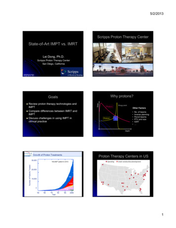
5/2/2013Scripps Proton Therapy CenterState-of-Art IMPT vs. IMRTLei Dong, Ph.D.Scripps Proton Therapy CenterSan Diego, CaliforniaAAPM-Midwest Chapter,Chicago, April 27, 2013Why protons?Review proton therapy technologies andIMPT Compare differences between IMRT andIMPT Discuss challenges in using IMPT inclinical practice DoseGoalsPhotonsBragg peakOther Factors ProtonsNo. of beamsInverse planningPencil beamsPTV and sizeIGRT DepthProton Therapy Centers in US100,000th patient in 2012MSKCC May 2008Bill Chu LBL1
5/2/2013Tim Williams – Economics of Proton TherapyASTRO 2007 Proton PanelWhat are different protonsystems?CyclotronPhysicsBeam Exit Requires higher energy: 250 MeV p 30cm Requires magnetic field for beam accelerationand beam steering2/3 speedof lightAlternating Radio Frequency (RF)voltage accelerates protons whenthey go across the gap in each turn.Modified fromY. JongenL. DongBeam Transportation (Magnets)Cyclotron11122
5/2/2013Scripps Proton Therapy Center LayoutF5G4G3G2F1CyclotronPatient Loading AreasPatient LocksPediatric PatientRecovery RoomLobbyFive Treatment Rooms3 – Isocentric Gantry Rooms2 – Fixed beam roomsDong/SPTCVarian/Accel’s Superconducting Cyclotron 4 meters in diameterSuperconducting Cooled to 4 Kelvin(-452.5 F!)The Principle of SynchrotronsHitachi and SiemensSynchrotrons:Both designs use 7 MeVmulti-turn injection forhigher intensity: 1.2 x10¹¹ protons per pulse(Hitachi)Both use RF drivenextraction for turningbeam on and off quickly( 200 μsec) and forgated respirationBoth are strong focusingwith similar magnetlayout and beam opticalLLUMC Synchrotron:Uses slow extractionwith 0.2 – 0.5 sec every2.2 secweak focusing3
5/2/2013Beam Delivery System Gantry Position beam in different angles (isocenttric)Mounting of imaging systemsLasersFixed beam port (horizontal/inclined)Nozzle Delivery the protonsDose monitoring systemBeam shaping devicesProtect patient from unwanted radiationImaging (optional)PTC-H 250 MeV Synchrotron RingMulti-room Systems A ProtonMachineat 90 mSiemens *Varian270 MeV proton synchrotron230MeV cyclotron235 MeV proton synchrotron320MeV/u synchrotron (20 cm – 12C)250 MeV proton synchrotron330 MeV/u proton synchrotron430 MeV/u synchrotron (30 cm – 12C)250MeV superconducting cyclotron* Proton and 12CSingle Room Systems Mevion:250 MeV gantry mounted compactsuperconducting synchrocyclotron. Inproduction. IBAProteusOne Tomotherapy250 MeV Dielectric Wall Accelerator.Compact linear accelerator. Feasibilitytesting.From 2D to 3DWhat have been changed?4
5/2/2013Revolution in RadiotherapyFrom 2D RT to the Current State of the ArtPatient Model for PlanningTreatment1980s - 2D RT 1990s - 3DCRT IMRT 2000s - IMRT IGRT Particle Therapy 2D RT70 Gy3D RT75.6 GyIMRTRectum SparingFletcher’s Textbook of Radiotherapy2D Isodose Calculation2D CompensatorFletcher’s Textbook of RadiotherapyWhat IsIntensity Modulated Radiation TherapyFletcher’s Textbook of Radiotherapy9-Field Head & Neck IMRT Case(IMRT)An approach to deliver conformal therapywith optimized non-uniform beam intensities: Use computer mathematical scoring to designnon-uniform radiation fields, Use dynamic motion of Multileaf Collimator to“paint” dose where desired - Intensity Patterns.LD 01/02Int J Radiat Oncol Biol Phys 2001;51:880-95
5/2/2013Computerized Treatment SystemMulti-leaf Collimator (MLC)Why is IMRT Possible Today? Computer power sufficient to calculateplans in reasonable amount of time Linear Accelerators are computer controlled Automated methods of machine setupand setup verification are convenient andcommonplace Multileaf collimators have goodmechanical precision and reliabilityLD 03/03New H&N Cases at MDACC (2007)From 2D to 3D to IMRT IMRT was themajor treatmentchoice.3DCRT:conventional RT FIF: manual fieldin-field IMRT IMRT: computeroptimized IMRT3DCRT,99, 16%IMRT-FIF,39, 6% 2D3DCRTIMRTIMRT,474, 78%Lei Dong 2/29/2008DoseTechnology Evolution in Proton TherapySingle Pencil Beam isinsufficient for Treating TumorBragg peakFrom Scatter to ScanningProtonsDepth6
5/2/2013Passively Scattered Protons2D CompensatorMohanConstant Range Modulation Widthand Distal Range CompensationFletcher’s Textbook of RadiotherapyMedulloblastoma (3 y old boy) Usually use rangemodulator wheels Distal rangecompensator (usuallyplastic or wax) Block/Aperture forcollimationPhotons(6 MV, 1 field)Chu, Ludewigt, Renner - Rev. Sci. Instr.Protons(SOBP, 1 field)Photon IMRT(15 MV, 9 field)Miralbell et al., IJROBP 2002Lung CancerProtonsX-rays (IMRT)New survey from the National Association for Proton Therapy(NAPT) and the Pediatric Proton Foundation (PPF):more children are being treated for cancer with proton therapy.613 children were treated with proton beam therapy in 2011, anincrease of 32 percent from 2010.Red is higher dose and blue is lower dose.Notice how much of heartand opposite lung is beingirradiated w/ x-rays.http://www.dotmed.com/news/story/19536Dong7
5/2/2013Constant Range Modulation Widthand Distal Range CompensationPencil beam scanning nozzleIntensityModulatedBeamPair ofQuadsScanningMagnetsVacuumChamberFast Usually use rangemodulator wheelsYSlowZBeammonitorX Distal rangecompensator (usuallyplastic or wax) Layer-by-layer scanning (changing energy is not easy) Spot scanning or raster scanning Max patient field (40x30) cm2 Block/Aperture forcollimationChu, Ludewigt, Renner - Rev. Sci. Instr.Pencil Beam Scanning is Simplyer Variable energy totreat tumor at differentdepthWhy is PBS Possible Today? Better power supply for magnets (dipole;quadruple; fast scanning coils)174 MeV More advanced accelerator technology Dose conformality forboth distal andproximal surfaces– More efficient accelerator– Better beam optics (smaller spots)– Fast energy change and current modulation Sharp pencil beam toreplace aperture– Automatic beam tuning and control system Scanning nozzle ( MLC)LD 04/13Advantages for using PencilBeam Scanning Fewer neutrons No physical compensator or aperture Sparing of healthy tissues proximal tothe target Large treatment field Intensity and energy modulated protontherapy (IMPT)Step-and-shoot delivery of protonbeam scanningDiscrete spot scanning methodBeam beamOFFprotonscanner settingtargetspotlayer– Inverse planning– Dynamic dose painting (control points)Modified from Martin Bues, PhD,From Varian8
5/2/20132D Isodose CalculationProton Beam Delivery Mode Passive Scatter (PS)– Use scatter technique to create a large treatmentfield– Range modulation is required Uniform Scanning (US)– Pre-programmed PBS with beam aperture (moretolerant of motion) Pencil Beam Scanning (PBS)– Use magnetic field to scan the treatment field– High intensity modulation (better plans)– Energy (range) can be changed spot-by-spotFletcher’s Textbook of RadiotherapyRaster Scan vs. Spot ScanEvolution of Proton Therapy Intensity modulation is much higher inspot scanning technique, which leads tobetter treatment plans Raster scanning may be more tolerantfor organ motionConventional PTPBS (Pencil Beam Scanning)/IMPT (Intensity ModulatedProton Therapy)Trofimov et al. IJROBP 69(2): 444-453. (2007)Photons vs. Future ProtonsIMRTIMPT(big spotsize)Bortfeld T. IMRT: “A review and a preview”, Phys. Med. Biol. 51(13), 2006.MD Anderson9
5/2/2013IMRT vs. IMPTPBS has better conformality and allows fewer fields3-fieldConventionalprotons IMPT typically use fewer beams 2-3 (IMPT) vs. 5-9 (IMRT)Range uncertainties – PTV concept CT image quality is important 2-fieldPencil-beamscanningprotons Normal tissue motion is importantIGRT Passive ScatterPBSMetal artifactsPatient scatterCBCT is lacking in proton therapy centers(today)Amin/MDACCImage Guidance in New SystemsImage GuidanceX-ray source to axisdistance 2 meters Detector to axisdistance 1 meter Courtesy of VarianRobotic CouchChallenges10
5/2/2013Inverse Planning ChallengesIMPTIMRT Beam anglePencil beam positionPencil beam intensity Beam anglePencil beam positionPencil beam intensityPencil beam energyPencil beam spacing f(E)Robustness considerationsRBE UncertaintiesCT Number UncertaintiesLeading to errors in predictedproton range in patientPaganetti, MGHper fractionVariations in Human TissueCompositionCT number to Proton Stopping Power Degeneracy problem HU (ρ1, Z1) HU (ρ2,Z2)SPR(ρ1, Z1) SPR(ρ2,Z2)SkinThyroid65Yang M.11
5/2/2013SPR uncertainties have a significant impact onproton dose distributionsImpact of 3.5% Range Uncertainty Uncertainty in SPR estimationCommonly it’s not visible on proton plans Estimated to be 3.5% (Moyers et al, 2001, 2009) 3.5%-3.5%0% uncertainty68Dong/MDACCBeam-Specific PTV for ProtonsPTV is invalid for proton planning of mobile targetPLANNEDIsodoselevels90270Relative Water Equivalent Depth Matrix“DELIVERED”2050809510070Courtesy of Martijn Engelsman (MGH)Free breathing TreatmentBeam Angle OptimizationMinimumbsPTVICTVGated treated on exhaleSetup error: 6mmInternal motion error: 0mm (AVG CT)Range error: 3.5% of total WETSmearing: 1cm12
5/2/2013Results (no gating)Materials and MethodsOrthogonal – 3sExperiment: 2D dose measurementSnoutMatrixxStepping motorMoving Platform(1D motion)Monitored by anexternal sensorLaserdisplacementsensor:Omron ZS-LDS2VTInter-fractional VariationsProton Lateral Penumbra vs. Distal Falloff95-50% 10 mm95-50% 4 mmDongImpact of Tumor Shrinkage on Proton Dose DistributionOriginal Proton PlanPlanning contours mapped to 24 in-room CTsDongThoracicDose recalculatedon the new anatomyH&NCSIPatient SetupProstateBucci/Dong et al. ASTRO Abstract, 200713
5/2/2013Setup Error and Positional Variation ofImmobilization DeviceCouch Edge EffectH. Yu et al.IMPT PlanningRobustness of IMPT for Multi-beam IMPT?PBS (Pencil Beam Scanning)/IMPT (Intensity ModulatedProton Therapy)Trofimov et al. IJROBP 69(2): 444-453. (2007)SFO vs. MFO Trofimov et al. IJROBP 69(2): 444‐453. (2007)IMRT vs. IMPT ExampleSingle-Field OptimizationTreat the entire target from one beamLess normal tissue sparing Relatively more robust for range uncertainties Multi-Field OptimizationSimultaneous optimization of multiple beams forone or more targets Better plan (on paper) and more tissue sparing Sensitive to range uncertainties and organmotion RapidArc 3F IMPT14
5/2/2013IMRT vs. IMPT ExampleIMRT vs. IMPT ExampleProstate RegionRapidArc Nodes Region3F IMPTIMRT vs. IMPT ExampleRapidArc IMRT vs. IMPT ExampleNodes RegionRapidArc Nodes Region3F IMPTSFO vs. MFO (IMPT)RapidArc 3F IMPTSFO vs. MFO (IMPT)Nodes Region3F SFO3F IMPTProstate Region3F MFO3F SFO3F MFO15
5/2/2013SFO vs. MFORobustness EvaluationRobustness EvaluationRobustness Evaluation3F SFO3F MFOProstate Region3F MFO PlanNodes Region3mm and 2%UncertaintiesRobustness Evaluation3mm and 2% Uncertainties3F SFO Plan3F MFO Plan3F MFO Plan3mm and 2%UncertaintiesRobustness EvaluationTarget Coverage and Hotspots3F MFO Plan3mm and 2%Uncertainties16
5/2/2013Robustness Evaluation3F SFOSummary3F MFOChallenges Development and optimal use of IMPTMeasurement dosimetryIn vivo range verificationRobustness plan evaluationRobust plan optimizationMotion management strategiesDose-guided setup and adaptive RTWorkflow optimization and efficiency Auto-segmentationWorkflow assessment and optimizationSetup outside of treatment roomOpportunities Development and optimal use of IMPTMeasurement dosimetryIn vivo range verificationRobustness plan evaluationRobust plan optimizationMotion management strategiesDose-guided setup and adaptive RTWorkflow optimization and efficiency Auto-segmentationWorkflow assessment and optimizationSetup outside of treatment roomWhat is IMRT?Future Proton TherapyMachines will be Differentfrom Today!I’M Really TiredWhat is IMPT?I’M Painfully Tired10217
New survey from the National Association for Proton Therapy (NAPT) and the Pediatric Proton Foundation (PPF): more children are being treated for cancer with proton therapy. 613 children were treated with proton beam therapy in 2011, an increase of 32 percent from 2010. Lung Cancer Protons X-rays (IMRT) Red is higher dose and blue is lower dose.


