Transcription
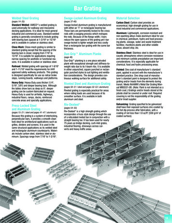
NATIONAL SWAGING MACHINEAND DIE WARNING, USE,MAINTENANCE AND APPLICATIONINFORMATIONNational Four Post Swaging MachineWARNING Misuse of swaging machine can result in seriousinjury or death.READ, UNDERSTAND, AND FOLLOW all theinformation in this warning document andthe instructions shown in “Wire Rope EndTerminations User’s Manual” before operating theswaging machine.Swaging machine operators must be trained inaccordance with the information supplied by TheCrosby Group LLC. THE SWAGING MACHINEOWNER IS RESPONSIBLE FOR THE TRAININGAND THE SAFE OPERATION OF THE SWAGINGMACHINE.Do not swage oversize parts.Only swage parts of the proper design, materialand hardness.If misused, dies and/or die holders may break.PROTECT YOURSELF AND OTHERS:Always stayaway from the sides of the swaging machineduring swaging operations and alert others in yourwork area.Do not shim between dies.Do not shim die or die holder unless swagingaluminum sleeves.Do not use die holders that are damaged or haveloose side rails or side plates.Tie rod nuts must be secured to the tie rods with asecondary retention system.Keep head, hands, and body away from movingswaging machine and die parts.Consult die manufacturer for correct use oftheir product.Adjust swaging machine tonnage to the WorkingLoad Limit (WLL) tonnage shown on the die blockbeing used. If the Working Load Limit is not legible,refer to Die height & width and correspondingWorking Load Limit (See Table 1). Failure to do socan result in serious injury or death.Copyright 2013 The Crosby Group LLCAll Rights ReservedOperation Safety NEVER use dies that are cracked, worn orabraded (galled). NEVER use dies that have an oversized cavity. ALWAYS use a matched set of dies. When swaging steel fittings,DO NOT SHIM DIES.Dies for steel fittings must be free to float and alignone to the other. When swaging aluminum fittings, THE STEEL DIESMUST BE SHIMMED. Shim the side of the die toensure the proper cavity alignment for flash removal. NEVER shim between the dies. When Swaging Crosby National fittings, use onlythe proper capacity swaging machine for the sizeof fitting used (See Swaging Capacity Chart). If theswaging machine capacity exceeds the die blockWorking Load Limit rating, adjust the swagingmachine tonnage to the Working Load Limit shownon the die block being used. See Table 1 for dieblock Working Load Limit. Always use the correct size and type of die for thesize wire rope fitting used. Make sure that the manufacturer’s die retentionlocking pin, bolt, or other device is engaged and hassecured the die before swaging. Make sure that thedies are straight, parallel, and perpendicular to eachother before and during the swaging procedure. Always lubricate die faces and cavities with lightweight oil. Progressive swaging of fittings must be done inaccordance with procedure shown in “Wire RopeEnd Terminations User’s Manual”. Only openchannel dies are to be used. Stop swaging when the cavity side of both diestouch. Observe the die closure from above andslightly to the side. The best position is to stand 45degrees to either side of the front. Make sure part is swaged to the recommended afterswage dimensions (See Crosby General Catalog or“Wire Rope End Terminations User’s Manual”, DieGuide, or Die Chart). If a swage fitting other than a Crosby National isused, determine adequacy of the termination by adestructive pull test. All swage sockets must be swaged with socket headadjacent to the socket relief (largest radius) onthe die. For special applications or conditions, contactCrosby National (501)962-3112.TABLE 1Die Size(Height x Width)2” x 3-1/2”2-1/2” x 4”2-1/2” x 5”4” x 7”5” x 7”6” x 12”Working Load Limit(WLL)*200 Ton Mark Series200 Ton National500 Ton Mark Series1,200 Ton Mark Series1,500 Ton National3,000 Ton National* Note: These Working Load Limits are for Crosby National Die Blocks only.The Working Load Limits of die blocks from other manufacturers may vary.65
Inspection Maintenance Safety Make sure the swager is in good operating conditionand that all gauges, indicators and controls areworking properly. Make sure all bolts and nuts are in place andtightened to recommended torque as shown in TableA, on page 13 for new style swaging machines, andTable B on page 14 for current swaging machines. Load block or die base plate surfaces must be tomanufacturers specifications for thickness andflatness to provide complete support of the dieduring swaging. Make sure die holder side rails are not bent, looseor damaged. Clean dies and die holder surfaces. Keep free ofmetal shavings, slag, grit, sand, floor dry, etc. Lubricate the four guide bushings daily with light oil.Die Working Load Limit Pressure Adjustmenton Lower Cylinder National 500 Ton through1500 Ton Swaging MachinesFollow this procedure to adjust swaging tonnage(pressure) on your swaging machine.1. Install the die holder(s) or die adapter with thedies to be used.2. Bring the dies together (without a part in thedies) until they just touch.3. Turn the tonnage control valve, which is locatedon the control panel left of the tonnage gauge,counter-clockwise about (6) six turns or untilknob no longer turns.4. Now (without a part in the dies) apply pressureto the dies by pressing the foot pedal marked“up”.A. If the tonnage is lower than desired WorkingLoad Limit, turn the valve clockwise whilecontinuing to press the foot pedal marked“up” until desired Working Load Limit isreached.B. If tonnage is higher than desired WorkingLoad Limit, release pressure by pressing thepedal marked “down”. Then repeat steps 2through 4.500 TonLargest Fitting Allowed to be Swaged(in.)*SwagingMethodFull DieDie Size(in.)S-505SleeveMarkSeries2-1/2 x 09Buttons7/8*1000 TonFull Die4x75x72-1/21-1/4*9/16*1-1/4*1500 TonFull Die5x76 x 123-1/21-1/4*9/16*1-1/4*6 x 124-1/23000 TonFull Die1-1/4*9/16*Die Working Load Limit Pressure Adjustment on3000 Ton Swaging MachineFor reducing tonnage, use selector switch on front ofcontrol panel to select lower tonnage (approximately1500 Tons) or 3000 Ton.WARNINGALWAYS USE 5 X 7 OR6 X 12 DIES AT 1500TON SETTING.WARNINGUSE ONLY 6 X 12 DIESON TONNAGE THATEXCEEDS 1500 TONS.Swaging Machine Capacity Chart forS-501 and S-502 Swage SocketSwaging Machine Capacity Chart forSwage Sleeves, Ferrules and ButtonsHydraulicSwagingMachineSize Inspect the rods for corrosion. Use #000 emery clothor steel wool to maintain a high polish surface. Do not increase the hydraulic system pressureabove the factory preset pressure of: 6500 psi for500 ton, 1000 ton and 1500 ton swaging machines –5000 psi for 3000 ton swaging machine. Under ordinary operating conditions, drain and cleanreservoir every two (2) years. Make certain that the hydraulic reservoir is full whenthe swager is in the full open position. Filters inside of the reservoir should be cleanedevery time the reservoir is drained and cleaned. TheRacine “tell-tale” suction filter should be cleanedevery six (6) hodMark Series2-1/2 x 54x75x73/4Progressive4x75x71-1/4Full Shank4x75x71Progressive4x71-1/2Full Shank5x76 x 121-1/4Progressive5x76 x 122Full Shank6 x 122Progressive6 x 122-1/21500 Tons* Largest size fitting available.3000 TonsLargest FittingAllowed to beSwaged(in.)*Full Shank500 Tons1000 TonsDieSize(in.)* Largest size fitting available.66Copyright 2013 The Crosby Group LLCAll Rights Reserved
“NEW STYLE” NATIONAL HYDRAULIC SWAGING MACHINETORQUE MAINTENANCE INFORMATIONItemNo. 114142221DescriptionCylinderHousing CapPistonTie RodTie Rod NutPlatenGuideGlandBushingMono SealSeal SpacerSide CylinderSide Cylinder MountLower BracketKnuckleUpper BracketCheck ValveCheck Valve SealTie Rod EyeboltCap EyeboltKeyBumperBumper StripRubber SkirtBottom of Seal CavityTable BTorque in Ft-LbsItem No.No.Req’d.1VariesDescriptionTie Rod Nut Jack-Bolts500 TonSwagingMachine1000 TonSwagingMachine1500 y24Check Valve Bolts100100100Weekly38Lower Bracket Bolts100100100Weekly48Upper Bracket Bolts100100100Weekly54Guide Bolts250250250Weekly68Bushing Screws151515Weekly74Key Monthly84Platen Bolts96Bumper Apron Screws1012Gland BoltsBolt SizeThreadFormDieHolderBoltTorqueCopyright 2013 The Crosby Group LLCAll Rights ReservedTorqueinft./ lbs.1/4 20 UNC135/16 18 UNC155/8 11 UNC2117/8 9 UNC58367
NATIONAL HYDRAULIC SWAGING MACHINETORQUE MAINTENANCE INFORMATIONItemNo. 11241244212821DescriptionCylinderHousing CapPistonTie RodNutPlatenGuideGlandBushingPacking SetPacking Gland NutPacking Gland SpacerStudCap ScrewCap ScrewLower BracketUpper Bronze RingUpper BracketMachine ScrewSide CylinderLower Bronze RingABCDEXY1441411BlockStudNutCopper “O” RingLock NutTop of CylinderBottom of Packing CavityTable ATorque in Ft. Lbs.Item No.Description500 TonSwagingMachine800 Ton 1000 TonSwaging SwagingMachine Machine1500 TonSwagingMachineMaintenanceSchedule5Tie Rod Nuts2000225025002500Weekly14Piston Bolts525600600700Monthly11Packing Gland Nuts (over spacers only) “all othershand tighten”200200200200Weekly15Platen Guide Bolts250250250250Weekly13Packing Gland BoltsSide Cylinder Bolts700100800N/A8001008001506 MonthsWeekly19Guide Bushing Bolts15151515Weekly80 M Piston Pump Pistons96 to 125 all Swaging MachinesBolt SizeThreadFormDieHolderBoltTorque68Torqueinft./ lbs.1/4 20 UNC135/16 18 UNC155/8 11 UNC2117/8 9 UNC583Copyright 2013 The Crosby Group LLCAll Rights Reserved
Die InformationCAUTION Improper die selection could result in significantloss of efficiency in the termination.National dies and die holders are made solely forswaging properly designed fittings on wire rope, and anyother uses are prohibited.The swaging operation results in a high degree of coldmetal flow. The movement that occurs between the fittingand the dies will cause wear of the dies. Therefore,to prolong the life of the dies, it is important to alwayslubricate die faces and cavities between each pass witha light weight oil or high pressure grease.When scores appear in the die cavities, the dies shouldbe removed from service.NEVER EXCEED THE WORKING LOAD LIMIT OFDIES OR DIE HOLDERS.All National Standard dies 1/4” through 1” include anopen channel die cavity and a tapered die cavity in thesame die block.Dies for S-505 Standard Steel Sleeves(Flemish Eyes)Die sizes for 1/4” through 1”Swaging 1/4” through 1” Standard Steel S-505 sleeveson Flemish Eye terminations requires the use of thetaper cavity only. Refer to page 24 of the Wire Rope EndTermination User’s Manual for proper die selection.Die sizes for 1-1/8” and aboveSwaging 1-1/8” and larger Standard Steel S-505 sleeveson Flemish Eye terminations requires using 2 sets ofopen channel dies (1st stage and 2nd stage) for eachsize. Beginning with the 1st stage die and finishingwith the 2nd stage die will achieve proper after swagedimensions. Dies for S-505 Sleeves 1-1/8” and larger aresingle cavity with open channel. Refer to page 24 of theWire Rope End Termination User’s Manual for properdie selection.Using S-505 Sleeves with Metric RopesAlthough Crosby National S-505 Standard Steel sleevesare designed to be used with most metric ropes, thereare selected “intermediate” sizes of metric ropes thatwhen swaged in standard National dies utilizing CrosbyNational S-505 sleeves do not achieve required afterswage dimensions and efficiencies. To ensure all 505sleeves achieve the required efficiency when used withmetric ropes, Crosby provides special National swagingdies to be used in conjunction with selected sizemetric ropes. These new dies will produce the requiredefficiencies and after swage dimensions.The table found on Page 25 of the Wire Rope EndTermination User’s Manual identifies the new dies thatare required to properly swage the selected intermediatesize wire ropes not covered in the standard productoffering found on Page 24 of the manual.Copyright 2013 The Crosby Group LLCAll Rights ReservedDies for 6mm through 26mm (except 12mm, 20mmand 24mm)Swaging on 6mm through 26mm metric ropes forFlemish Eye slings requires the selection of the properS-505 Standard Steel sleeve and the use of the taperedcavity only. Refer to page 24 of the Wire Rope EndTermination User’s Manual for proper sleeve anddie selection.Dies for 12mm, 20mm and 24mmSwaging on 12mm, 20mm and 24mm metric ropes forFlemish Eye slings requires the selection of the properS-505 Standard Steel sleeve and the use of both theopen cavity and tapered cavity in special dies. Referto page 25 of the Wire Rope End Termination User’sManual for proper sleeve and die selection.Dies for 28mm and largerSwaging on 28mm and larger metric ropes for FlemishEye slings requires the selection of the proper S-505Standard Steel sleeve and the use of 2 sets of openchannel dies (1st stage and 2nd stage) for each size.Beginning with the 1st stage die and finishing withthe 2nd stage die will achieve proper after swagedimensions. Dies for S-505 sleeves 28mm and largerare single cavity with open channel. Refer to page 24 ofthe Wire Rope End Termination User’s Manual for propersleeve and die selection.Important: If the specific size metric rope required isnot listed on page 24 of the Wire Rope End TerminationUser’s Manual refer to Intermediate Metric Die Chart onpage 25 of the manual for proper sleeve anddie selection.Dies for QUIC-PASS Swaging System – 1/4”through 1-1/2”The QUIC-PASS swaging system allows “Flemishstyle” wire rope terminations to be swaged in only twopasses. This is accomplished while maintaining currentlypublished efficiency ratings and utilizing National SwageS-505 Standard “COLD TUFF” Steel Sleeves.The special design of the QUIC-PASS dies allows theswaging process to be completed in just two passes,resulting in a 50-75% reduction in the number of passesrequired with conventional swaging systems. Unlikestandard round dies, the QUIC-PASS dies closecompletely with each pass, resulting in an increase inoverall swaging process efficiencies (the job can beperformed quicker), a reduction in the complexity ofswaging (the concern for excess flashing between dieshas been eliminated) and a reduction in training timeneeded for operators (more user friendly).The finished sleeve has a “Hex” appearance thatprovides a QUIC-CHECK look to determine if thetermination has been swaged and provides a flatsurface that allows for ease of I.D. stamping on thefinished sleeve. Refer to page 24 of the Wire Rope EndTermination User’s Manual for proper die selection.69
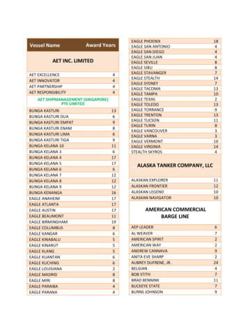
Dies for S-501 & S-502 Swage SocketsSwaging all S-501 & S-502 Swage Sockets requires theuse of single cavity die. This is a special die designedwith a relief for swage sockets and extra length to swagethe full length of the shank. Refer to pages 36 and 37 ofthe Wire Rope End Termination User’s Manual for properdie selection.Swage Sockets for Spiral Strand RopeOur tests indicate that if the spiral strand is 1 x 19 orgreater, and the ultimate strength does not exceedTable 4 of ASTM A586, you can use dies for size swagesockets up to the 1-1/4”. For sizes greater than 1-1/4” thefollowing table will apply:If the strand is of greater strength than Table 4 or hasless metallic area, we must recalculate the design andtest for adequacy.Two Cavity DieDies for S-506 Turnback SleevesTurnback eye terminations using 5/16” through 1” S-506Sleeves utilize the S-505 Standard Steel Sleeve die (1stStage open channel die only). The 1-1/4” S-506 Sleeveutilizes the 1-3/8” socket (S-501 and S-502) die. Referto page 46 of the Wire Rope End Termination User’sManual for proper die selection.Dies for S-409 ButtonsButtons are swaged in open channel dies. Refer to page42 of the Wire Rope End Termination User’s Manual forproper die selection.Specific recommended swaging practices can be foundin each product section of this brochure. The properdie selection and the recommended maximum afterswage dimensions are referenced in the section of thisbrochure that contains the product you are swaging. Thisinformation can also be found in The Crosby GeneralCatalog (See Section “Wire Rope End Terminations”),the National Swage Die Guide, or by referring to theNational Swage Die Chart.Dies and die adapters to fit other type swaging machinesare available upon request (Refer to page 19).Never use dies that are cracked, worn or abraded(galled).Single Cavity Die70Copyright 2013 The Crosby Group LLCAll Rights Reserved
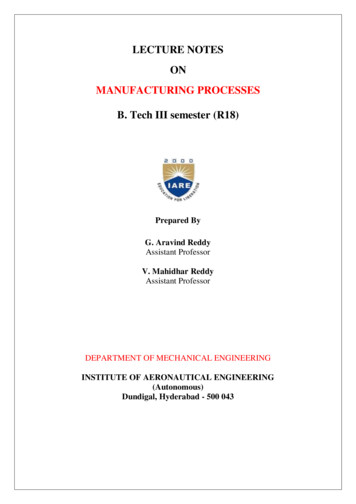
After Swage Inspection ProceduresWARNING Read, understand, and follow these instructionsbefore using the National QUIC-PASS SwagingSystem. Improper after swage dimensions can result in slingfailure resulting in property damage, serious injuryor death. Always gauge or measure the after swagedimensions to ensure proper sling performance. Using National Swaging System with ropes andtermination styles other than shown in theseprocedures may reduce the performance of thetermination and lead to premature failure. When using rope constructions other than shown inthis procedure, the termination must be destructivetested and documented to prove adequacy of theassembly to be manufactured. The QUIC-PASS Swaging System is designed onlyfor “Flemish Eye” terminations using National S-505Standard Steel Sleeves. The QUIC-PASS Swaging System is not designed forCable-Laid wire rope slings or fiber core wire rope.Checking Swaging DimensionsOne of the important considerations in producing a qualitytermination is the overall diameter of the fitting after theswaging process is complete. Since all dies wear, andthe swaged fitting used in terminations have spring back,the results of swaging should be checked periodically todetermine the wear condition of the die as well as to ensurethe fitting is swaged to proper dimensions.Key Facts About After Swage Dimensions:1. In addition to worn dies, not achieving the proper afterswage dimension can also be due to the die not beingfully closed during swaging. Dies showing excessive wearshould be replaced.2. The effective swaging that dies can accomplish stopswhen the die lands touch each other. Any continuedswaging adds needless wear and strain on the dies andswaging machine.3. By placing a light oil on the die faces and in the cavity, thedies will be lubricated as well as protected.4. The oozing of the oil from the faces of the dies as theytouch will indicate when the dies have closed. At thispoint, stop the swaging cycle.5. Additional swaging adds needless wear and strain to thedies and swaging machine.6. Never use dies that are cracked, worn or abraded(galled).7. The Crosby Group does not recommend the checking ofdie dimensions as an acceptable method of determiningthe quality of a swage sleeve, button, ferrule, or socket.8. It is our recommendation that the checking of the afterswage dimension of the swaged fitting is the mostaccurate indicator of a properly swaged termination.Measuring the die cavity only is not an acceptableprocess control check.9. If the die cavity wears, the dies are not closed completelyduring swaging. If an inadequate number of presses areused, it could be quickly identified by checking the afterswage dimension of the part.10. Swaging Machine not producing sufficient tonnage willaffect after swage dimensions.Copyright 2013 The Crosby Group LLCAll Rights ReservedNo-Go Gauge InformationTo assist in checking the after swage dimensions of the fitting,the Crosby Group provides the National No-Go Gauges.When used correctly the National No-Go Gauges candetermine if the fittings were swaged to the proper diameter.We would recommend that all Crosby products or productswaged in Crosby dies be checked with the proper gauge todetermine the acceptability of the swaging process. Gauges are made of hardened alloy steel and machinedto strict tolerances. Gauge can be used to verify that all fittings have beenswaged properly. After swage dimensions not within the maximumlimits may result from worn dies or improper swagingtechniques. Other type gauges are available upon request. National No-Go Gauges are available for a variety ofproducts (See Table 1). No-Go Gauges and QUIC-PASS No-Go Gauges arenot interchangeable.Table 1Fitting and Size505 Sleeve 1/4 - 7/8505 Sleeve 1 - 1-1/2505 Sleeve 1-3/4505 Sleeve 2505 Sleeve 2-1/4505 Sleeve 2-1/2505 Sleeve 2-3/4505 Sleeve 3505 Sleeve 3-1/2505 Sleeve 3-3/4505 Sleeve 4501/502 Socket 1/4 - 1501/502 Socket 1-1/8 - 1-3/4501/502 Socket 2Part 5Using No-Go GaugesWhen swaged properly, the gauge will go up and down (seeFigure 1) and around the full length of the fitting (see Figure 2).For the proper after swage dimensions, see the section in thispublication for the specific product you are swaging.Figure 1Figure 271
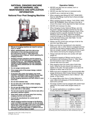
QUIC-PASS No-Go GaugesAs a further aid, QUIC-PASS No-Go gauges are available forchecking the sleeve’s dimensions after swaging is complete. Gauges are made of hardened alloy steel and machinedto strict tolerances. Gauge can be used to verify that all sleeves have beenswaged properly. “After Swage” dimensions not within the maximum limitsmay result from worn dies or improper swaging techniques.QUIC-PASS No-Go GaugesSleeve and SizeNo-Go Gauge for S-505 1/4” - 7/8”No-Go Gauge for S-505 1” - 1-1/4”No-Go Gauge for S-505 1-3/8” - 1-1/2”Stock No.192370519237121923714QUIC-PASS Maximum After Swage DimensionsSize(in.)1/45/16 - 3/87/16 - 1/29/16 - 5/83/47/811-1/81-1/41-3/81-1/2Maximum “After Swage” .1702.4052.6102.835Stock No.1923705Stock No.1923712Stock No.1923714Use a National QUIC-PASS No-Go Gauge to check the after swagedimensions to ensure that it has beenswaged to the proper dimension. Whenswaged properly, the gauge will slide upand down the full length of the sleeve onall three sets of opposing flats.132231Important Safety Information Crosby does not recommend a “Texas Tuck” styletermination with Crosby National S-505 “COLD TUFF ”Standard Steel Sleeves. Only Crosby National S-505 “COLD TUFF ” StandardSteel Sleeves are recommended when using the QUICPASS Swaging System. National S-505 Standard Steel Sleeves, when used withthe QUIC-PASS Swaging System, are only recommendedfor use with one (1) part 6 X 19 or 6 X 37, IPS or XIP(EIP), XXIP (EEIP), RRL, IWRC rope. The condition of the swaging machine can cause sleeve“After Swage” size not to be within the proper dimensions.Example: worn bushings, loose tie rods, loose dieholders, misaligned platens, worn pins, worn linkage, etc.72 Swaging dies being worn, damaged, misused, orundersized can cause sleeve “After Swage” size not to bewithin the proper dimension. Swaging die holders excessively worn, damaged, misusedor loose can cause sleeve “After Swage” size not to bewithin the proper dimension. Only use QUIC-PASS dies and die holders inspected and properly secured inNational swaging machines. Always refer to Warning and Application informationfound in the Crosby General Catalog and Wire Rope EndTerminations User’s Manual.Copyright 2013 The Crosby Group LLCAll Rights Reserved
machine tonnage to the Working Load Limit shown on the die block being used. See Table 1 for die block Working Load Limit. Always use the correct size and type of die for the size wire rope fitting used. Make sure that the manufacturer's die retention locking pin, bolt, or other device is engaged and has secured the die before swaging.