Transcription
RGV036-072R-410A Single-Package RooftopGas Heat/Electric CoolingInstallation InstructionsCONTENTSPageSAFETY CONSIDERATIONS . . . . . . . . . . . . . . . . . . . . . 1MODEL NUMBER NOMENCLATURE ANDDIMENSIONS . . . . . . . . . . . . . . . . . . . . . . . . . . . . . . . . . . . 2Rated Indoor Airflow . . . . . . . . . . . . . . . . . . . . . . . . . . . . 3INSTALLATION . . . . . . . . . . . . . . . . . . . . . . . . . . . . . . . . . 7Jobsite Survey . . . . . . . . . . . . . . . . . . . . . . . . . . . . . . . . . 7Step 1 — Plan for Unit Location . . . . . . . . . . . . . . . . . . 7 ROOF MOUNTStep 2 — Plan for Sequence of Unit Installation . . . . 7 CURB-MOUNTED INSTALLATION PAD-MOUNTED INSTALLATION FRAME-MOUNTED INSTALLATIONStep 3 — Inspect Unit . . . . . . . . . . . . . . . . . . . . . . . . . . . 7Step 4 — Provide Unit Support . . . . . . . . . . . . . . . . . . . 7 ROOF CURB MOUNT SLAB MOUNT (HORIZONTAL UNITS ONLY) ALTERNATE UNIT SUPPORT (IN LIEU OF CURBOR SLAB MOUNT)Step 5 — Field Fabricate Ductwork . . . . . . . . . . . . . . . 9Step 6 — Rig and Place Unit . . . . . . . . . . . . . . . . . . . . . 9 POSITIONING ON CURBStep 7 — Convert to Horizontal and ConnectDuctwork . . . . . . . . . . . . . . . . . . . . . . . . . . . . . . . . . . . . . 10Step 8 — Install Outside Air Hood . . . . . . . . . . . . . . . 11 ECONOMIZER AND TWO-POSITION DAMPERHOOD PACKAGE REMOVAL AND SETUP (FACTORYOPTION) ECONOMIZER AND TWO-POSITION HOODStep 9 — Units with Hinged Panels Only . . . . . . . . . 12Step 10 — Install Flue Hood . . . . . . . . . . . . . . . . . . . . 12Step 11 — Install Gas Piping . . . . . . . . . . . . . . . . . . . . 13 FACTORY-OPTION THRU-BASE CONNECTIONS(GAS CONNECTIONS)Step 12 — Install External Condensate Trapand Line . . . . . . . . . . . . . . . . . . . . . . . . . . . . . . . . . . . . . . 15Step 13 — Make Electrical Connections . . . . . . . . . . 16 FIELD POWER SUPPLY UNITS WITH FACTORY-INSTALLED NON-FUSEDDISCONNECT UNITS WITHOUT FACTORY-INSTALLEDNON-FUSED DISCONNECT ALL UNITS CONVENIENCE OUTLETSPage FACTORY-OPTION THRU-BASE CONNECTIONS(ELECTRICAL CONNECTIONS) UNITS WITHOUT THRU-BASE CONNECTIONS(ELECTRICAL CONNECTIONS) FIELD CONTROL WIRING THERMOSTAT HEAT ANTICIPATOR SETTINGS HOT GAS RE-HEAT CONTROL CONNECTIONS TYPICAL UNIT WIRING DIAGRAMSIntegrated Gas Controller . . . . . . . . . . . . . . . . . . . . . . 25EconoMi er X (Factory Option) . . . . . . . . . . . . . . . . . 27Smoke Detectors . . . . . . . . . . . . . . . . . . . . . . . . . . . . . . 41Step 14 — Adjust Factory-Installed Options . . . . . . 42Step 15 — Install Accessories . . . . . . . . . . . . . . . . . . . 42Step 16 — Fan Speed Set Up . . . . . . . . . . . . . . . . . . . . 43START-UP CHECKLIST . . . . . . . . . . . . . . . . . . . . . . . CL-1SAFETY CONSIDERATIONSImproper installation, adjustment, alteration, service,maintenance, or use can cause explosion, fire, electricalshock or other conditions which may cause personal injury orproperty damage. Consult a qualified installer, service agency, or your distributor or branch for information or assistance.The qualified installer or agency must use factory-authorizedkits or accessories when modifying this product. Refer to theindividual instructions packaged with the kits or accessorieswhen installing.Follow all safety codes. Wear safety glasses and workgloves. Use quenching cloths for brazing operations andhave a fire extinguisher available. Read these instructionsthoroughly and follow all warnings or cautions attached to theunit. Consult local building codes and appropriate nationalelectrical codes (in USA, ANSI/NFPA70, National ElectricalCode (NEC); in Canada, CSA C22.1) for specialrequirements.It is important to recognize safety information. This is the. When you see this symbol on thesafety-alert symbolunit and in instructions or manuals, be alert to the potentialfor personal injury.Understand the signal words DANGER, WARNING,CAUTION, and NOTE. These words are used with the safetyalert symbol. DANGER identifies the most serious hazards whichwill result in severe personal injury or death. WARNING signifieshazards which could result in personal injury or death. CAUTIONis used to identify unsafe practices, which may result in minorpersonal injury or product and property damage. NOTE is used tohighlight suggestions which will result in enhanced installation, reliability, or operation.525 01 1501 0009/17/2018
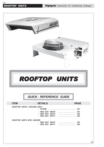
AVERTISSEMENTWARNINGFailure to follow this warning could result in personalinjury or death.Disconnect gas piping from unit when leak testing atpressure greater than 0.5 psig (3450 Pa). Pressuresgreater than 0.5 psig (3450 Pa) will cause gas valvedamage resulting in hazardous condition. If gas valve issubjected to pressure greater than 0.5 psig (3450 Pa), itmust be replaced before use. When pressure testingfield-supplied gas piping at pressures of 0.5 psig (3450Pa) or less, a unit connected to such piping must be isolated by closing the manual gas valve.WARNINGFailure to follow this warning could cause personal injury,death and/or equipment damage.R-410A refrigerant systems operate at higher pressuresthan standard R-22 systems. Do not use R-22 serviceequipment or components on R-410A refrigerantequipment.WARNINGFailure to follow this warning could cause personal injuryor death.Relieve pressure and recover all refrigerant before system repair or final unit disposal. Wear safety glasses andgloves when handling refrigerants. Keep torches andother ignition sources away from refrigerants and oils.RISQUE D’INTOXICATION AU MONOXYDE DE CARBONESi ces directives ne sont pas suivies, cela peut entraînerdes blessures graves ou une intoxication au monoxydede carbone pouvant causer la mort, si des produits decombustion s’infiltrent dans le bâtiment.Vérifier que toutes les ouvertures pratiquées dans le murextérieur autour du ou des tuyaux d’évent (et de la prised’air) sont scellées de manière à empêcher l’infiltrationde produits de combustion dans le bâtiment.Veiller à ce que la ou les sorties de l’évent de l’appareilde chauffage (et la prise d’air) ne soient, en aucunefaçon, obstruées, quelle que soit la saison.WARNINGFIRE HAZARDFailure to follow this warning could result in personal injury, death, and/or property damage.Inlet pressure tap set screw must be tightened and1/8-in. NPT pipe plug must be installed to prevent gas leaks.GAS VALVEINLET PRESSURETAP SET SCREWCAUTIONFailure to follow this caution may result in personal injury.Sheet metal parts may have sharp edges or burrs. Usecare and wear appropriate protective clothing, safetyglasses and gloves when handling parts and servicing airconditioning equipment.WARNINGCARBON-MONOXIDE POISONING HAZARDFailure to follow instructions could result in severe personal injury or death due to carbon-monoxide poisoning,if combustion products infiltrate into the building.Check that all openings in the outside wall around thevent (and air intake) pipe(s) are sealed to prevent infiltration of combustion products into the building.Check that furnace vent (and air intake) terminal(s) arenot obstructed in any way during all seasons.WARNINGFIRE HAZARDFailure to follow this warning could result in personal injury, death, and/or property damage.Manifold pressure tap set screw must be tightened and1/8-in. NPT pipe plug must be installed to prevent gasleaks.MANIFOLD PRESSURETAP SET SCREWMANIFOLDGAS VALVEMODEL NUMBER NOMENCLATURE ANDDIMENSIONSSee Fig. 1 for RGV036-072 model number nomenclature.See Fig. 2 for unit dimensional drawings. Figure 2 shows serviceclearance dimensions.2Specifications subject to change without notice.525 01 1501 00
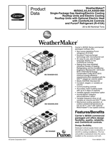
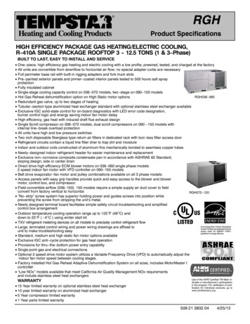
Rated Indoor AirflowTable 1 — Rated Indoor AirflowTable 1 lists the rated indoor airflow used for the AHRIefficiency rating for the units covered in this document.MODEL NUMBERRGV036RGV048RGV060RGV072RATED INDOOR AIRFLOW (CFM)1050150020002400MODEL SERIESRGV060LDDA0AAAPosition Number1234567091011121314R RooftopTypeG Gas Heat / Electric CoolingV 14 SEER (036-060)15 IEER (072)Standard Efficiency036 36,000 BTUH 3 Tons048 48,000 BTUH 4 Tons060 60,000 BTUH 5 Tons072 72,000 BTUH 6 TonsNominal Cooling CapacityK 208/230 1 60H 208/230 3 60L 460 3 60DEFSRT VoltageLow HeatMedium HeatHigh HeatLow Heat, Stainless Steel Heat ExchangerMedium Heat, Stainless Steel Heat ExchangerHigh Heat, Stainless Steel Heat ExchangerD Direct Drive V-Blade – Standard StaticE Direct Drive V-Blade – High StaticF Direct Drive V-Blade – Medium StaticG Direct Drive V-Blade – High Static with Hot Gas Re-HeatA NoneB Economizer with Barometric relief, OA Temp sensorE Economizer with Barometric relief CO2 sensor, OA Temp sensorH Economizer with Barometric relief, enthalpy sensorL Economizer with Barometric relief CO2 sensor, enthalpy sensorP 2-Position Damper (036-060 models only)U Temp Ultra Low Leak Economizer with Barometric reliefW Enthalpy Ultra Low Leak Economizer with Barometric relief0A 4B AA AT BB BP BR CJ ABCDEF Heating Capacity1Motor Option (Indoor Fan)Outdoor Air Options / Control 2No OptionsNon Fused Disconnect SwitchHinged Access PanelsUn-Powered Convenience OutletPowered Convenience OutletReturn Air Smoke DetectorSupply Air Smoke DetectorCondensate Overflow SwitchFactory Installed Options3Aluminum / Copper Cond & Evap CoilPrecoat Alum/Copper Cond with Alum / Copper Evap (3 phase only)E Coated Alum/Copper Cond with Alum / Copper Evap (3 phase only)E Coated Alum / Copper Cond & Evap (3 phase only)Copper/Copper Cond & Alum/Copper Evap (3 phase only)Copper/Copper Cond & Evap (3 phase only)Condenser / Evaporator Coil ConfigurationA Economizer control (W7212) for EconoMiZer IV (036-060 models)B Economizer control (W7220) for EconoMiZer X (036-072 models)Economizer ControlNOTE: Factory-installed options are NOT available on single phase models. This includes economizers and 2-position damper.See Specification Sheet for actual heating capacities.2See Specification Sheet for details.3Combinations of factory-installed options are available, see Specifications Sheet for details.1Fig. 1 — RGV036-072 Model Number Nomenclature (Example)525 01 1501 00Specifications subject to change without notice.3
Fig. 2 — Unit Dimensional Drawing4Specifications subject to change without notice.525 01 1501 00
Fig. 2 — Unit Dimensional Drawing (cont)525 01 1501 00Specifications subject to change without notice.5
Fig. 2 — Unit Dimensional Drawing (cont)6Specifications subject to change without notice.525 01 1501 00
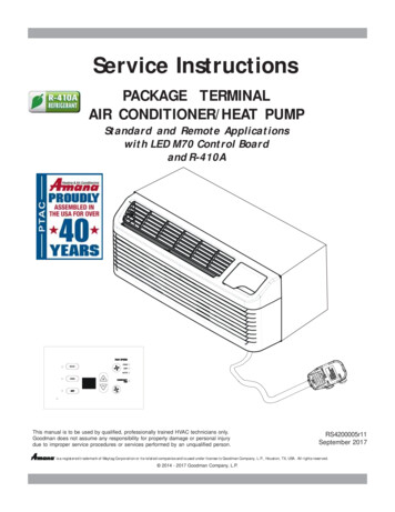
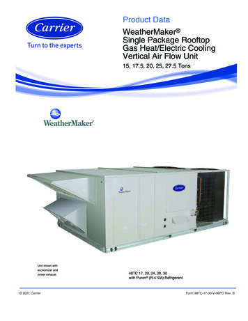
INSTALLATIONStep 2 — Plan for Sequence of Unit InstallationJobsite SurveyComplete the following checks before installation.1. Consult local building codes and the NEC (NationalElectrical Code) ANSI/NFPA 70 for special installationrequirements.2. Determine unit location (from project plans) or selectunit location.3. Check for possible overhead obstructions which mayinterfere with unit lifting or rigging.Step 1 — Plan for Unit LocationSelect a location for the unit and its support system (curbor other) that provides for the minimum clearances requiredfor safety. This includes the clearance to combustiblesurfaces, unit performance and service access below,around and above unit as specified in unit drawings. SeeFig. 2 on page 5.NOTE: Consider also the effect of adjacent units.Be sure that unit is installed such that snow will not blockthe combustion intake or flue outlet.Unit may be installed directly on wood flooring or onClass A, B, or C roof-covering material when roof curb isused.Do not install unit in an indoor location. Do not locate airinlets near exhaust vents or other sources of contaminatedair. For proper unit operation, adequate combustion andventilation air must be provided in accordance with Section5.3 (Air for Combustion and Ventilation) of the National FuelGas Code, ANSI Z223.1 (American National Standards Institute) and NFPA (National Fire Protection Association)54 TIA-54-84-1. In Canada, installation must be in accordance with the CAN1-B149 installation codes for gas burning appliances.Although unit is weatherproof, avoid locations that permitwater from higher level runoff and overhangs to fall onto theunit.Locate mechanical draft system flue assembly at least4 ft (1.2 m) from any opening through which combustionproducts could enter the building, and at least 4 ft (1.2 m)from any adjacent building (or per local code). Locate theflue assembly at least 10 ft (3.05 m) from an adjacent unit’sfresh air intake hood if within 3 ft (0.91 m) of same elevation(or per local code). When unit is located adjacent to publicwalkways, flue assembly must be at least 7 ft (2.1 m) abovegrade.Select a unit mounting system that provides adequateheight to allow installation of condensate trap per requirements. Refer to Step 12 — Install External Condensate Trapand Line on page 15 for required trap dimensions.ROOF MOUNTCheck building codes for weight distribution requirements. Unit operating weights are shown in Table 2.Table 2 — Operating WeightsRGVBase UnitEconomizerVerticalHorizontalHot Gas Re-HeatSystemCu FinsPowered OutletCurb14 in. (356 mm)24 in. (610 mm)525 01 1501 00UNIT LB (KG)036048060072482 (219) 543 (246) 556 (252) 607 (275)50 (23)80 (36)50 (23)80 (36)50 (23)80 (36)50 (23)80 (36)50 (23)50 (23)80 (3680 (36)25 (11)35 (16)43 (20)35 (16)56 (25)35 (16)56 (25)35 (16)115 (52)197 (89)115 (52)197 (89)115 (52)197 (89)115 (52)197 (89)The support method used for this unit will dictate differentsequences for the steps of unit installation. For example, oncurb-mounted units, some accessories must be installed onthe unit before the unit is placed on the curb. Review the following for recommended sequences for installation steps:CURB-MOUNTED INSTALLATION1. Install curb2. Install field-fabricated ductwork inside curb3. Install accessory thru-base service connection package(affects curb and unit) (refer to accessory installationinstructions for details)4. Prepare bottom condensate drain connection to suitplanned condensate line routing (refer to Step 12 —Install External Condensate Trap and Line on page 15for details)5. Rig and place unit6. Install outdoor air hood7. Install flue hood8. Install gas piping9. Install condensate line trap and piping10. Make electrical connections11. Install other accessoriesPAD-MOUNTED INSTALLATION1. Prepare pad and unit supports2. Check and tighten the bottom condensate drain connection plug3. Rig and place unit4. Convert unit to side duct connection arrangement5. Install field-fabricated ductwork at unit duct openings6. Install outdoor air hood7. Install flue hood8. Install gas piping9. Install condensate line trap and piping10. Make electrical connections11. Install other accessoriesFRAME-MOUNTED INSTALLATIONFrame-mounted applications generally follow the sequence for a curb installation. Adapt the sequence as required to suit specific installation plan.Step 3 — Inspect UnitInspect unit for transportation damage. File any claimwith transportation agency.Confirm before installation of unit that voltage, amperageand circuit protection requirements listed on unit data plateagree with power supply provided.On units with hinged panel option, check to be sure alllatches are snug and in closed position.Locate the carton containing the outside air hood parts.Do not remove carton until unit has been rigged and locatedin final position.Step 4 — Provide Unit SupportROOF CURB MOUNTAccessory roof curb details and dimensions are shown inFig. 3 (on page 8). Assemble and install accessory roof curbin accordance with instructions shipped with the curb.NOTE: The gasketing of the unit to the roof curb is critical fora watertight seal. Install gasket supplied with the roof curbas shown in Fig. 3. Improperly applied gasket can also resultin air leaks and poor unit performance.Curb should be level. This is necessary for unit drain tofunction properly. Unit leveling tolerances are shown inFig. 4. Refer to Accessory Roof Curb Installation Instructions for additional information as required.Specifications subject to change without notice.7
Fig. 3 — Roof Curb Details8Specifications subject to change without notice.525 01 1501 004 137.7]24"[610]CRRFCURB002A01SUPPLY AIR20.41"[518.3]40.69"[1033.5]SUPPLY AIROPENING21.84"[554.7]1/3/4"[44.5]RETURN AIR3.00"[76.2]13.78"[350.0]16.03"[407.2]ERETURN AIROPENING14"[356]CRRFCURB001A0111.96"[303.8]AROOF CURBACCESSORY #E32.19"[817.6]70.87"[1800.2]VIEW "B"DUCT(FIELD SUPPLIED)GASKET(SUPPLIED WITH CURB)CORNER DETAILROOFING MATERIAL(FIELD SUPPLIED)CANT STRIP(FIELD SUPPLIED)ROOFING FELT(FIELD SUPPLIED)COUNTER FLASHING(FIELD SUPPLIED)TYPICAL (4) SIDES"A"8 9/16"[217.5] WIDEINSULATED DECK PANELSUPPLY AIRSEE VIEW "B"3'-1 3/16"[944.6]1/2" [12.7] NPT3/4" [19] NPTGAS FITTING3/4" [19] NPTPOWER WIRINGFITTING1-3/4"[44.5]RETURN AIR1' 4-13/16"[427] INSIDE11 3/4"[298.5] WIDEINSULATED DECK PANELSTHRU THE BOTTOMTHRU THE CURBGAS CONNECTION TYPEGAS SERVICE PLATETHRU THE CURBDRILL HOLE2" [50.8] @ASSEMBLY (IFREQUIRED)(SEE NOTE #8)1.00"[25.4]1-3/4"[44.4]E-ESECTIONSCALE CTOR PKG. ACC.NAIL (FIELD SUPPLIED)RIGID INSULATION(FIELD SUPPLIED)7/16"[11]UNIT"A"NOTES:1. ROOFCURB ACCESSORY IS SHIPPED DISASSEMBLED.2. INSULATED PANELS: 25.4 [1"] THK. POLYURETHANE FOAM, 44.5 [1-3/4] # DENSITY.3. DIMENSIONS IN [ ] ARE IN MILLIMETERS.4. ROOFCURB: 18 GAGE STEEL.5. ATTACH DUCTWORK TO CURB. (FLANGES OF DUCT REST ON CURB).6. SERVICE CLEARANCE 4 FEET ON EACH SIDE.7.DIRECTION OF AIR FLOW.8. CONNECTOR PACKAGE CRBTMPWR001A01 IS FOR THRU-THE-CURB GAS TYPEPACKAGE CRBTMPWR003A01 IS FOR THRU-THE-BOTTOM TYPE GAS CONNECTIONS.1-3/4"[44.4]SEE NOTE #21/2" [12.7] NPTACCESSORY CONVENIENCEOUTLET WIRING CONNECTOR48TC4004275' 7-3/8"[1711.3]2-3/8"[61]1/2" [12.7] NPTCONTROL WIRINGFITTING
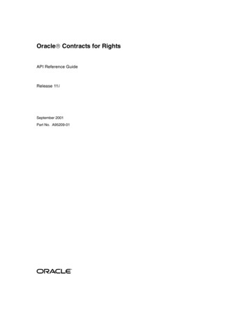
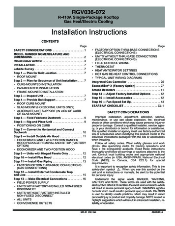
Step 6 — Rig and Place UnitCAUTIONCABMAXIMUM ALLOWABLEDIFFERENCE IN. (MM)A-B0.5 (13)B-C1.0 (25)A-C1.0 (25)Fig. 4 — Unit Leveling TolerancesInstall insulation, cant strips, roofing felt, and counterflashing as shown. Ductwork must be attached to curb andnot to the unit. The accessory thru-the-base power and gasconnection package must be installed before the unit is seton the roof curb. If field-installed thru-the-roof curb gas connections are desired, use factory-supplied 1/2-in. pipe coupling and gas plate assembly to mount the thru-the-roof curbconnection to the roof curb. Gas connections and powerconnections to the unit must be field-installed after the unit isinstalled on the roof curb.If electric and control wiring is to be routed through thebasepan, attach the accessory thru-the-base service connections to the basepan in accordance with the accessoryinstallation instructions.SLAB MOUNT (HORIZONTAL UNITS ONLY)Provide a level concrete slab that extends a minimum of6 in. (150 mm) beyond unit cabinet. Install a gravel apron infront of condenser coil air inlet to prevent grass and foliagefrom obstructing airflow.NOTE: Horizontal units may be installed on a roof curb ifrequired.ALTERNATE UNIT SUPPORT (IN LIEU OF CURB ORSLAB MOUNT)A non-combustible sleeper rail can be used in the unitcurb support area. If sleeper rails cannot be used, supportthe long sides of the unit with a minimum of 3 equallyspaced 4-in. x 4-in. (102 mm x 102 mm) pads on each side.Step 5 — Field Fabricate DuctworkCabinet return-air static pressure (a negative condition)shall not exceed 0.35 in. wg (87 Pa) with economizer or 0.45in. wg (112 Pa) without economizer.For vertical ducted applications, secure all ducts to roofcurb and building structure. Do not connect ductwork to unit.Fabricate supply ductwork so that the cross sectional dimensions are equal to or greater than the unit supply ductopening dimensions for the first 18 in. (458 mm) of ductlength from the unit basepan.Insulate and weatherproof all external ductwork, joints,and roof openings with counter flashing and mastic in accordance with applicable codes.Ducts passing through unconditioned spaces must be insulated and covered with a vapor barrier.If a plenum return is used on a vertical unit, the returnshould be ducted through the roof deck to comply with applicable fire codes.A minimum clearance is not required around ductwork.525 01 1501 00Failure to follow this caution may result in damage toroofing materials.Membrane roofs can be cut by sharp sheet metal edges.Be careful when placing any sheet metal parts on suchroof.Keep unit upright and do not drop. Spreader bars arerequired. Rollers may be used to move unit across a roof.Rigging materials under unit (cardboard or wood) must beremoved PRIOR to placing the unit on the roof curb. Levelby using unit frame as a reference. See Table 2 and Fig. 5for additional information.Lifting holes are provided in base rails as shown in Fig. 5.Refer to rigging instructions on unit.Rigging materials under unit (cardboard or wood to prevent basepan damage) must be removed PRIOR to placingthe unit on the roof curb.When using the standard side drain connection, ensurethe red plug in the alternate bottom connection is tight. Dothis before setting the unit in place. The red drain plug an betightened with a 1/2-in. square socket drive extension. Forfurther details, see Step 12 — Install External CondensateTrap and Line on page 15.Before setting the unit onto the curb, recheck gasketingon curb.POSITIONING ON CURBCAUTIONFailure to follow this caution may result in injury or equipment damage.All panels must be in place when rigging. Unit is not designed for handling by fork truck when panels or packaging are removed.If using top crate as spreader bar, once unit is set, carefully lower wooden crate off building roof top to ground.Ensure that no people or obstructions are below prior tolowering the crate.Position unit on roof curb so that the following clearancesare maintained: 1/4 in. (6.4 mm) clearance between the roofcurb and the base rail inside the front and rear, 0.0 in. clearance between the roof curb and the base rail inside on theduct end of the unit. This will result in the distance betweenthe roof curb and the base rail inside on the condenser endof the unit being approximately 1/4 in. (6.4 mm).Although unit is weatherproof, guard against water fromhigher level runoff and overhangs.CAUTIONFailure to follow this caution may result in equipmentdamage.All panels must be in place when rigging. Unit is not designed for handling by fork truck when panels or packaging are removed.Flue vent discharge must have a minimum horizontalclearance of 4 ft (1220 mm) from electric and gas meters,gas regulators, and gas relief equipment. Minimum distancebetween unit and other electrically live parts is 48 inches(1220 mm).Specifications subject to change without notice.9
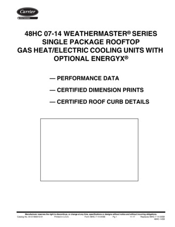
"B"36"- 54"(914-1371)REQUIREDSPREADERBARSDETAIL "A"PLACE ALL SEAL STRIP IN PLACEBEFORE PLACING UNIT ON ROOF CURB.DUCT END"C""A"UNITRGV036RGV048RGV060RGV072SEE DETAIL "A"MAX 55NOTES:1. SPREADER BARS ARE REQUIRED. Top damage will occur if spreader bars are not used.2. Dimensions in () are in millimeters.3. Hook rigging shackles through holes in base rail, as shown in Detail A. Holes in base rails are centered around the unit center ofgravity. Use wooden top to prevent rigging straps from damaging unit.Fig. 5 — Rigging DetailsFlue gas can deteriorate building materials. Orient unitsuch that flue gas will not affect building materials. Locatemechanical draft system flue assembly at least 48 in.(1220 mm) from an adjacent building or combustiblematerial.NOTE: Installation of accessory flue discharge deflector kitwill reduce the minimum clearance to combustible materialto 18 in. (460 mm).After unit is in position, remove rigging skids and shippingmaterials.REMOVABLE HORIZONTALRETURN DUCT OPENING COVERStep 7 — Convert to Horizontal and ConnectDuctwork (When Required)Unit is shipped in the vertical duct configuration. Unitwithout factory-installed economizer or return air smoke detector option may be field-converted to horizontal ductedconfiguration. To convert to horizontal configuration, removescrews from side duct opening covers (see Fig. 6) and remove covers. Use the screws to install the covers on verticalduct openings with the insulation-side down. The panelsmust be inserted into the notches on the basepan to properly seal. The notches are covered by the tape used to securethe insulation to the basepan and are not easily seen. SeeFig. 7 for position of the notches in the basepan. Sealsaround duct openings must be tight. Secure with screws asshown in Fig. 8. Cover seams with foil duct tape.Field-supplied flanges should be attached to horizontalduct openings and all ductwork should be secured to theflanges. Insulate and weatherproof all external ductwork,joints, and roof or building openings with counter flashingand mastic in accordance with applicable codes.Do not cover or obscure visibility to the unit’s informativedata plate when insulating horizontal ductwork.REMOVABLE HORIZONTALSUPPLY DUCT OPENING COVERFig. 6 — Horizontal Conversion PanelsNOTCHESNOTCHESBASEPANFig. 7 — Location of Notches10Specifications subject to change without notice.525 01 1501 00
SCREWSHOOD PARTSPLASTIC TIE WRAPQTY (2)DUCT COVERSSHEET METALFACE UPSCREWS FORMETAL TRAYQTY (2)BASEPANFig. 10 — Economizer and Two-Position DamperHood Parts Location3.Fig. 8 — Horizontal Duct Panels In PlaceStep 8 — Install Outside Air HoodECONOMIZER AND TWO-POSITION DAMPER HOODPACKAGE REMOVAL AND SETUP (FACTORYOPTION)NOTE: Economizer and two-position damper are not available as factory installed options for single phase (-K voltagecode) models. Two position damper is not available forRGV072 models.The hood is shipped in knock-down form and must befield assembled. The indoor coil access panel is used as thehood top while the hood sides, divider and filter are packaged together, attached to a metal support tray using plasticstretch wrap, and shipped in the return air compartment behind the indoor coil access panel. The hood assembly’s metal tray is attached to the basepan and also attached to thedamper using two plastic tie-wraps.1. To gain access to the hood, remove the filter accesspanel. See Fig. 9.Carefully lift the hood assembly (with metal tray)through the filter access opening and assemble per thesteps outlined in the Economizer Hood and Two-Position Hood section below.ECONOMIZER AND TWO-POSITION HOODNOTE: If the power exhaust accessory is to be installed onthe unit, the hood shipped with the unit will not be used andmust be discarded. Save the aluminum filter for use in thepower exhaust hood assembly.1. The indoor coil access panel will be used as the top ofthe hood. Remove the screws along the sides and bottom of the indoor coil access panel. See Fig. 11.TOPPANELFILTER ACCESS OILACCESSPANELFig. 11 — Indoor Coil Access Panel RelocationCOMPRESSORACCESS PANELOUTDOOR-AIR OPENING ANDINDOOR COIL ACCESS PANELFig. 9 — Typical Access Panel Locations2.2.Swing out indoor coil access panel and insert the hoodsides under the panel (hood top). Use the screws provided to attach the hood sides to the hood top. Usescrews provided to attach the hood sides to the unit.See Fig. 12.Locate the (2) screws holding the metal tray to thebasepan and remove. Locate and cut the (2) plastic tiewraps securing the assembly to the damper. SeeFig. 10. Be careful to not damage any wiring or cut tiewraps securing any wiring.525 01 1501 00Specifications subject to change without notice.11
Step 9 — Units with Hinged Panels OnlyTOPPANELINDOOR COILACCESS PANELLEFTHOODSIDEIf the unit does not have hinged panels, skip this step andcontinue at Step 10 below.Relocate latch shipped inside the compressor compartment behind the hinged compressor door to location shownin Fig. 14 after unit installation.SCREW19 1/16”B(483mm)COMPRESSOR DOOROUTDOOR COIL33 3/8”LATCH(848mm)HOOD DIVIDERFig. 12 — Economizer Hood Construction3.4.5.6.7.Remove the shipping tape holding the economizer barometric relief damper in place (economizer only).Insert the hood divider between the hood sides. SeeFig. 12 and 13. Secure hood divider with 2 screws oneach hood side. The hood divider is also used as thebottom filter rack for the aluminum filter.Open the filter clips which are located underneath thehood top. Insert the aluminum filter into the bottom filterrack (hood divider). Push the filter into position past theopen filter clips. Close the filter clips to lock the filter intoplace. See Fig. 13.Caulk the ends of the joint between the unit top paneland the hood top.Replace the filter access panel.Fig. 14 — Compressor Door Latch LocationStep 10 — Install Flue HoodFlue hood is shipped screwed to the basepan beside theburner compartment access panel. Remove from shippinglocation and using screws provided, install flue hood andscreen in location shown in Fig. 15.DIVIDERFLUE OPENINGOUTSIDEAIRBLOWERACCESSPANELFig. 15 — Flue Hood RELIEFFILTERCLIPFig. 13 — Economizer Filter Installation12Specifications subject to change without notice.525 01 1501 00
Step 11 — Install Gas PipingInstallation of the gas piping must be accordance with local building codes and with applicable national codes. InU.S.A., refer to NFPA 54/ANSI Z223.1 National Fuel GasCode (NFGC). In Canada, installation must be accordancewith the CAN/CSA B149.1 and CAN/CSA B149.2 installationcodes for gas burning appliances.This unit is factory equipped for use with Natural Gas fuelat elevations up to 2000 ft (610 m) above sea level. Unitmay be field converted for operation at elevations above2000 ft (610 m) and/or for use with liquefied petroleum fuel.See accessory kit installation instructions regarding theseaccessories.NOTE: Furnace gas input rat
Do not install unit in an indoor location. Do not locate air inlets near exhaust vents or other sources of contaminated air. For proper unit operation, adequate combustion and ventilation air must be provided in accordance with Section 5.3 (Air for Combustion and Ventilation) of the National Fuel Gas Code, ANSI Z223.1 (American National .