Transcription
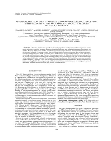
ProductDataWeatherMaker 48/50A2,A3,A4,A5020-060Single-Package Gas Heating/Electric CoolingRooftop Units and Electric CoolingRooftop Units with Optional Electric Heatwith ComfortLink Controlsand Puron Refrigerant (R-410A)20 to 60 Nominal TonsWeatherMaker ��s 48/50A Series commercialpackaged rooftops offer: Non-ozone depleting Puronrefrigerant (R-410A) Novation heat exchangertechnology with microchannel coil An easy-to-use, plain Englishlanguage display on theComfortLink controls Ratings that meet ASHRAE(American Society of Heating,Refrigerating, and Air-ConditioningEngineers) Standard 90.1-2016 andIECC (International EnergyConservation Code) IECC-2015minimum energy efficiencyrequirements when equipped with theSAV (staged air volume) option Meets ASHRAE Standard 62 Constant, staged, or variable airvolume Communicating controls Accurately match building loadswith up to 5 steps of capacity Variable capacity compressor option Humidi-MiZer adaptivedehumidification option Variable frequency drive on allvariable air volume and SAV units Mechanical cooling operation atoutdoor ambient temperatures aslow as 32 F (–20 F with optionalMotormaster V fan speed control)Features/Benefitsa48-8351Carrier’s 48/50A commercialpackaged unit offers designflexibility, quality, reliability,and ComfortLink controls.Design flexibility48/50A060 Carrier Corporation 2017Dedicated vertical supply/return units(A2,A3) are ideal for new construction orretrofit to existing installations. The lowunit profile is maintained when the unit isinstalled on the accessory roof curb.Form 48/50A-17PD
Features/Benefits (cont)The ducts are attached directly tothe roof curb to allow all ductwork tobe completed before the unit ispositioned.Dedicated horizontal units (A4,A5)are ideal for replacement or applications such as through-the-wall wheresound must be attenuated before theduct penetrates the roof. Ducts connect directly to the unit. Horizontalunits may be curb or slab mounted.The unit cabinet may be providedwith optional double wall constructionfor indoor air quality sensitive applications.ComfortLink controlsFactory-installed ComfortLink controls provide the capability for freestanding operation or may be linkedwith a more extensive system. Factoryinstalled and programmed BACnet*communication capability providessimple integration with the buildingHVAC system (e.g., terminal devices),an i-Vu Open Control System, or aBACnet building automation system.The ComfortLink controls also havethe capability to communicate with theCarrier Comfort Network (CCN) system. This communication flexibility allows simple system integration, as wellas data collection, trending, monitoring, and alarm displays.The 48/50A Series may also be configured to communicate via Modbus†or LonWorks** protocols, if required bythe application.The ComfortLink controls are yourlink to a world of simple and easy-touse rooftop units that offer outstandingperformance and value. When usedwith a space temperature sensor, theComfortLink controls maintain controlover the economizer and condenserfans and help optimize the performance of the multiple refrigeration circuits as conditions change, resulting inthe following features: higher part load efficiency better control of temperature andhumidity superior reliability redundant refrigeration systems*BACnet is a registered trademark of ASHRAE(American Society of Heating, Refrigerating,and Air-Conditioning Engineers).†Modbus is a registered trademark of SchneiderElectric.**LonWorks is a registered trademark of EchelonCorporation.2 high ambient cooling operation at115 F low ambient cooling operation at32 F as standard (optionalMotormaster V inverter fan speedcontrol for operation down to–20 F)The ComfortLink scrolling marqueedisplay is very easy to use. Messagesare displayed in easy to understand English. No decoding is required. A scrolling readout provides detailed explanations of control information. Only 4,large, easy-to-use buttons are requiredto maneuver through the entire menu.The readout is designed to be visibleeven in the brightest sunlight. A handheld Navigator accessory can be usedfor added service flexibility.The ComfortLink controls provideunparalleled service diagnostic information. Temperature and pressure canbe read from the display with no needfor separate gages. Other data, such ascompressor cycles, unit run timehours, and current alarms can also beaccessed. A history of alarms is alsoavailable for viewing.A service run test can be very helpfulwhen troubleshooting. The user canrun test major components to help determine the root cause of a problem.The unit can be run-tested before aninstallation is complete to support asatisfactory start-up.To further support reliability, theComfortLink controls prevent reversecompressor rotation.No laptop computers are requiredfor start-up. Time schedules are built inand the scrolling marquee display provides easy access to set points.Table of contentsThe ComfortLink controller accepts input from a CO2 sensor and asmoke detector. Both are available asfactory-installed options or as fieldinstalled accessories.The unit-mounted terminal strip allowscontrol of the unit with a standard thermostat. Expensive interface devices arenot required.Environmentally balancedMaking an environmentally responsibledecision is possible when using Carrier’s Puron refrigerant (R-410A).Puron refrigerant (R-410A) is an HFCrefrigerant that does not contain chlorine that is damaging to the ozone layer.This refrigerant is a safe, efficient, andenvironmentally balanced refrigerant.Quality and reliabilityExcellent full and part load efficienciesare achieved by using multiple scrollcompressors and indoor coils with intertwined dual refrigerant circuits. Thecompressors are equipped with crankcase heaters and protected by electronic sensors and logic to control minimum on and off times and reverse rotation. The refrigerant circuits are bothelectrically and mechanically independent, to provide standby capability,should one circuit require service.Totally enclosed outdoor-fan motorsare designed for many years of troublefree operation.Positive-locking bearings for the indoor fan reduce vibration of the supplyfan assembly and remain locked duringthe life of the bearing.Unit capacity controlThe units have up to 5 stages of capacitycontrol to match the load requirementsPageFeatures/Benefits . . . . . . . . . . . . . . . . . . . . . . . . . . . . . . . . . . . . . . . . . 1-4Model Number Nomenclature . . . . . . . . . . . . . . . . . . . . . . . . . . . . . . . . . 5,6Ratings and Capacities . . . . . . . . . . . . . . . . . . . . . . . . . . . . . . . . . . . . . . 7-9Physical Data . . . . . . . . . . . . . . . . . . . . . . . . . . . . . . . . . . . . . . . . . . 10-17Options and Accessories . . . . . . . . . . . . . . . . . . . . . . . . . . . . . . . . . . . . 18Base Unit Dimensions . . . . . . . . . . . . . . . . . . . . . . . . . . . . . . . . . . . . 19-36Accessory Dimensions . . . . . . . . . . . . . . . . . . . . . . . . . . . . . . . . . . . . 37-42Selection Procedure. . . . . . . . . . . . . . . . . . . . . . . . . . . . . . . . . . . . . . . . 43Performance Data . . . . . . . . . . . . . . . . . . . . . . . . . . . . . . . . . . . . . . . 44-82Electrical Data . . . . . . . . . . . . . . . . . . . . . . . . . . . . . . . . . . . . . . . . . 83-107Controls . . . . . . . . . . . . . . . . . . . . . . . . . . . . . . . . . . . . . . . . . . . . 108-121Application Data . . . . . . . . . . . . . . . . . . . . . . . . . . . . . . . . . . . . . . 122,123Typical Wiring Schematics . . . . . . . . . . . . . . . . . . . . . . . . . . . . . . . 124-129Guide Specifications . . . . . . . . . . . . . . . . . . . . . . . . . . . . . . . . . . . 130-141
of the conditioned space. Unit operationwill closely match the load and maintaincomfort in the most energy-efficientmanner.Variable capacity scroll compressorIn air conditioning applications, theload may vary significantly, requiring ameans to vary the system capacity foroptimal performance and control.The A Series large rooftop units withoptional variable capacity scroll compression provide a highly efficientmeans of capacity control using scrollcompressors. The digital compressortechnology provides smooth, vibrationfree operation by axially unloading thecompliant scrolls.By varying the amount of time thatthe scrolls are unloaded, the A Seriesunit is able to precisely match the system capacity to the space load. Thisfeature can reduce energy consumption, provide better dehumidification,reduce compressor cycling, and improve comfort in the space.Humidi-MiZer adaptive dehumidification systemCarrier's Humidi-MiZer adaptive dehumidification system is an all-inclusive factory-installed option that canbe ordered with WeatherMaker 48/50A2,A3,A4,A5 rooftop unit.This system expands the envelope ofoperation of the A Series rooftop toprovide unprecedented flexibilitythat will meet year-round comfortconditions.The Humidi-MiZer adaptive dehumidification system has the industry'sonly dual dehumidification mode setting. The WeatherMaker rooftop, coupled with the Humidi-MiZer adaptivedehumidification system, is capable ofmodulating between normal designcooling mode, subcooling mode, andhot gas reheat mode.Normal design cooling mode will operate under the normal sequence ofoperation. Subcooling mode will operate to satisfy part load type conditions.Hot Gas Reheat mode will operatewhen outdoor temperatures diminishand the need for latent capacity is required for sole humidity control. HotGas Reheat mode will provide neutralair for maximum dehumidificationoperation.The WeatherMaker A Series generation version of Carrier's Humidi-MiZersystem includes refrigerant modulatingvalves that provide variable flow bypassaround the condenser. This innovativefeature ensures exact control of thesupply-air temperature as the unit lowers the evaporator temperature to increase latent capacity.Additionally, when the space requires dehumidification only, theHumidi-MiZer system can increase hotdischarge gas bypass to the HumidiMiZer coil in order to heat the air tothe exact neutral state required—noovercooling or overheating with latentcapacity similar to that provided in thefull subcooling mode.Variable frequency drive (VFD)Variable air volume (VAV) units usestate of the art variable frequencydrive (VFD) to control duct staticpressure for optimum supply fanenergy savings.VAV features include: control of cooling and heating (ifequipped with heat) in both occupied and unoccupied mode support of optional space temperature sensor control of modulating economizer toprovide free cooling when outdoorconditions are suitable support of IAQ (indoor air quality)sensor support linkage to ComfortID VAV systemsStaged air volume units use the VFDto allow for a configurable high andlow fan speed. In this way, duringtimes of part load or low demand, indoor fan motor power consumptioncan be reduced.Factory-installed economizerAn optional integrated economizerpermits cooling by using an outdoor airsensor. The economizer uses ultra-lowleak blades for tight sealing and a robust drive design for long life.The economizer operates in conjunction with mechanical cooling,when required, and is factory installedfor either vertical or horizontaloperation. The factory-supplied andfield-installed rain hood/filter assemblyis designed to prevent moisture or objects from entering the unit.Exhaust air relief is available for allunits: barometric relief (CV [constantvolume] or VAV) power exhaust modulating power exhaust high capacity power exhaustField-adjustable set points on modulating power exhaust prevent spacepressurization problems. Factoryinstalled relief options are unit mounted on downflow units. Accessoriesmust be duct mounted for horizontalapplications.Novation heat exchangertechnologyThe Novation heat exchanger designwith microchannel condenser coil is arobust, cost-effective alternative totraditional coil design for standardapplications. Microchannel coils arealso sturdier than other coil types,making them easier to clean withoutcausing damage to the coil.Due to the compact, all-aluminumdesign, microchannel coils reduceoverall unit operating weight. Thestreamlined microchannel coil also reduces refrigerant charge by up to 40%.Microchannel coils are not recommended by Carrier for marine, coastal,or industrial environments, unlessCarrier-approved coating is applied.Gas heating unitsIntegrated gas unit controller(IGC) (gas heating units only) —All ignition components are containedin the compact IGC, which is easilyaccessible for servicing. The IGC control board, designed and manufacturedexclusively for Carrier rooftop units,provides built-in diagnostic capability.An LED (light-emitting diode) simplifiestroubleshooting by providing visualfault notification and system statusconfirmation.The IGC also contains an anti-cycleprotection for gas heat operation.After 4 continuous cycles on the unithigh-temperature limit switch, the gasheat operation is disabled and an errorcode is issued. This feature greatlyimproves reliability of the rooftop unit.The IGC also contains burner control logic for accurate and dependablegas ignition. This LED fault-notificationsystem reduces service person troubleshooting time and minimizes service3
Features/Benefits (cont)costs. The IGC can also increase heating efficiency by controlling evaporatorfan on and off delays.Efficient, dependable operation —Tubular, dimpled gas heat exchangersoptimize heat transfer for improved efficiency. The tubular design permits hotgases to make multiple passes acrossthe path of the supply air. The dimpleddesign creates a turbulent gas flow to increase heating efficiency. The extrathick Alumagard heat exchanger coating provides corrosion resistance tolengthen coil life. An optional stainlesssteel heat exchanger is also available.The unsightly appearance of fluestacks is eliminated and the effects ofwind on heating operations are diminished by the induced draft combustionsystem. The inducer fan draws hotcombustion gas through the heatexchanger at the optimum rate for themost effective heat transfer. Induceddraft heating systems are safer thanpositive pressure, forced draft heatingsystems. With the induced draftheating system, the heat exchangeroperates under negative pressure,preventing flue gas leakage into theindoor supply air.During the heating mode, theevaporator-fan relay automaticallystarts the evaporator fan after the heatexchanger warms up to a suitabletemperature. To increase efficiencyand comfort, the 30-second fan delayprevents cold air from entering thesupply duct system when the conditioned space is calling for heat.The direct-spark ignition systemsaves operating expense when compared to pilot ignition systems. Nocrossover tube is required; therefore,no sooting or pilot-fouling problemscan occur.All 48A standard units are designedfor natural gas. An accessory LP (liquidpropane) conversion kit is available.Safety is built in — All 48A unitshave a flame rectification sensor toquickly sense the burner flame andignite burners almost immediately.4The controls are designed to shutdown the unit during any flame outageor circuit failure. The flame sensor reacts quickly to these events. In theevent of a shutdown, an error code isissued at the IGC board.The heating safety controls will shutdown the unit if they detect a problem.If excessive temperatures develop, limitswitches shut off the gas valve. After4 continuous short cycles of the hightemperature limit switch, the IGCboard locks out the gas heat cycle toprevent any further short cycles. Thissafety feature is provided exclusively onCarrier rooftop units. The rolloutswitch also de-energizes the gas valvein the event of a flame rollout.Support of fire and smoke control isincluded with an optional ComfortLinkcontrols expansion module (CEM).Staged gas unit heatingThe staged gas control option adds thecapability to control the rooftop unit’sgas heating system to a specified supply air temperature set point for purposes of tempering a cool mixed-aircondition, or for reheat when the mechanical cooling is being used for dehumidification. The gas heating systememploys multiple heating sections.Each section is equipped with a twostage gas valve. The gas valves aresequenced by a factory-installed stagedgas controller (SGC), as required, tomaintain the user-specified supply airset point. Up to 11 stages of heatingcontrol are available, based on quantityand heating capacity sizes of the individual heat exchanger sections provided in the base unit. In addition to providing system control for temperingand reheat operation, the SGC alsoprovides Demand Heating control forthe first stage (W1 or low-heat) heatingmode. The heating capacity will alwaysgo to 100% for second stage (W2 orhigh-heat) operation.Tempering supply air is desirablewhen rooftop units are operating inventilation mode (economizer only operation) at low outdoor temperatures.At low outdoor temperatures, themixed-air temperature (combination ofreturn-from-space temperature andoutdoor/ventilation air temperature)may become too low for the comfortof the occupants or for the terminalreheat systems. The tempering function adds incremental steps of heatcapacity to raise the temperature ofthe mixed air up to levels suitable fordirect admission into the occupiedspace or to levels consistent withreheat capabilities of the d design (vertical or horizontal) requires no alteration time to convert in the field. Single point electricalconnections are standard on all units.Electrical service access can be madethrough roof curb or side of unit.All units are equipped with the ComfortLink control system as standard.The ComfortLink control system has afully alphanumeric display and keypad. The display has expandable textmessages that eliminate the need tolook up coded display information.The unit also supports use of the enhanced multiple line display that can beconnected through a phone jack connection at either end of the unit. Thestandard microprocessor controls replace the need for field-installed antishort cycle timers. The controls arecompatible with either a room sensoror conventional thermostat with noneed to install an accessory interface.In addition, no special tools are required to run the unit through its operational steps. The unit can be run-tested before an installation is complete toensure satisfactory start-up.Hinged access panels are located foreasy access to standard serviceablecomponents for maintenance. No fasteners need to be removed, which reduces servicing time and helps preventroof leaks caused by discarded screws.Color-coded wiring permits easy tracing and diagnostics.
Model number nomenclature48A2,A3,A4,A5 UNITS48A2D050FEG648 – Cooling Unit with Gas HeatConfigurationA2 – CV/SAV Vertical with ComfortLink Controlsand Puron Refrigerant (R-410A)A3 – VAV Vertical with ComfortLink Controlsand Puron Refrigerant (R-410A)A4 – CV/SAV Horizontal with ComfortLink Controlsand Puron Refrigerant (R-410A)A5 – VAV Horizontal with ComfortLink Controlsand Puron Refrigerant (R-410A)Heat OptionsD – Low Gas HeatE – High Gas HeatF – Low Gas Heat with Humidi-MiZerG – High Gas Heat with Humidi-MiZerM – Low Gas Heat StainlessN – High Gas Heat StainlessS – Staged Low Gas Heat StainlessT – Staged High Gas Heat StainlessV – Staged Low Gas Heat Stainless with Humidi-MiZerW – Staged High Gas Heat Stainless with Humidi-MiZerUnit Size - Nominal Tons020 – 20025 – 25027 – 27030 – 30035 – 35040 – 40050 – 50060 – 60Control Options– – No OptionsA – Controls Expansion Module onlyB – CO2 SensorC – Smoke DetectorD – CO2 Sensor and Smoke Detector (return air section mounted)E – Plugged Filter IndicatorF – Plugged Filter Indicator and CO 2 SensorG – Plugged Filter Indicator and Smoke DetectorH – Plugged Filter Indicator, CO2 and Smoke DetectorJ – CO2 Sensor with Controls Expansion ModuleK – Smoke Detector with Controls Expansion ModuleL – CO2 Sensor and Smoke Detector with Controls Expansion ModuleM – Plugged Filter Indicator with Controls Expansion ModuleN – Plugged Filter Indicator and CO2 Sensor with ControlsExpansion ModuleP – Plugged Filter Indicator and Smoke Detector with ControlsExpansion ModuleQ – Plugged Filter Indicator, CO2 and Smoke Detector withControls Expansion ModuleLEGENDAl— AluminumCu— CopperCV— Constant VolumeMCHX — Microchannel Heat ExchangerSAV — Staged Air VolumeVAV — Variable Air VolumeVFDB — Variable Frequency Drive Bypass21GNFactory-Installed OptionsRefer to price pages foravailable option codes.Packaging/Communication1 – Domestic3 – ExportA – Domestic with BACnet Communication OptionC – Export with BACnet Communication OptionDesign Series2 – A Series3 – 050Voltage1 – 575-3-605 – 208/230-3-606 – 460-3-60Coil Options– – Al/Cu Cond, Al/Cu EvapA – Al/Cu Cond, Al/Cu Evap with Variable CompressorB – Cu/Cu Cond, Al/Cu Evap with Variable CompressorC – Cu/Cu Cond, Al/Cu EvapD – Al/Cu Cond Precoat, Al/Cu Evap with Variable CompressorE – Al/Cu Cond Precoat, Al/Cu EvapF – E-coated Al/Cu, Al/Cu EvapG – MCHX Cond, Al/Cu EvapH – E-coated MCHX Cond, Al/Cu EvapJ – MCHX Cond with Security Grille, Al/Cu EvapK – E-coated MCHX Cond with Security Grille, Al/Cu EvapL – E-coated Al/Cu Cond, Al/Cu Evap with Variable CompressorM – MCHX Cond, Al/Cu Evap with Variable CompressorN – E-coated MCHX Cond, Al/Cu Evap with Variable CompressorP – MCHX Cond with Security Grille, Al/Cu Evap withVariable CompressorQ – Al/Cu Cond, Al/Cu Evap with Hot Gas BypassR – Cu/Cu Cond, Al/Cu Evap with Hot Gas BypassS – Al/Cu Cond Precoat, Al/Cu Evap with Hot Gas BypassT – E-coated Al/Cu, Al/Cu Evap with Hot Gas BypassV – MCHX Cond, Al/Cu Evap with Hot Gas BypassW – E-coated MCHX Cond, Al/Cu Evap with Hot Gas BypassX – MCHX Cond with Security Grille, Al/Cu Evap with Hot Gas BypassY – E-coated MCHX Cond with Security Grille,Al/Cu Evap with Hot Gas BypassZ – E-coated MCHX Cond with Security Grille,Al/Cu Evap with Variable CompressorMotor OptionsNoVFDA – 5 HP JC – 10 HP 1D – 15 HP 2E – 20 HP 3F – 25 HP 4G – 30 HP 5H – 40 HP 6VFDB– 5 HP– 10 HP– 15 HP– 20 HP– 25 HP– 30 HP– 40 HPLNPQRSTVFD– 5 HP– 10 HP– 15 HP– 20 HP– 25 HP– 30 HP– 40 HPQuality AssuranceISO 9001:2008-certified processesNOTES:1. VAV and SAV models are equipped with a supply fan motor variablefrequency drive (VFD).2. All indoor fan motors meet the minimum efficiency requirements asestablished by the Energy Independence and Security Act (EISA)2007.5
Model number nomenclature (cont)50A2,A3,A4,A5 UNITS50 A2 E050 F E G 62 1 GN50 – Cooling UnitFactory-Installed OptionsRefer to price pages foravailable option codes.ConfigurationA2 – CV/SAV Vertical with ComfortLink Controlsand Puron Refrigerant (R-410A)A3 – VAV Vertical with ComfortLink Controlsand Puron Refrigerant (R-410A)A4 – CV/SAV Horizontal with ComfortLink Controlsand Puron Refrigerant (R-410A)A5 – VAV Horizontal with ComfortLink Controlsand Puron Refrigerant (R-410A)Packaging/Communication1 – Domestic3 – ExportA – Domestic with BACnet Communication OptionC – Export with BACnet Communication OptionHeat Options- – No heatB – 36/27 kWC – 72/54 kWD – 54/42 kWE – 108/81 kWF – No heat with Humidi-MiZerG – 36/27 kW with Humidi-MiZerH – 72/54 kW with Humidi-MiZerJ – 54/42 kW with Humidi-MiZerK – 108/81 kW with Humidi-MiZerUnit Size - Nominal Tons020 – 20025 – 25027 – 27030 – 30035 – 35040 – 40050 – 50060 – 60Control Options– – No OptionsA – Controls Expansion Module onlyB – CO2 SensorC – Smoke DetectorD – CO2 Sensor and Smoke Detector (return section mounted)E – Plugged Filter IndicatorF – Plugged Filter Indicator and CO 2 SensorG – Plugged Filter Indicator and Smoke DetectorH – Plugged Filter Indicator, CO2 and Smoke DetectorJ – CO2 Sensor with Controls Expansion ModuleK – Smoke Detector with Controls Expansion ModuleL – CO2 Sensor and Smoke Detector with Controls Expansion ModuleM – Plugged Filter Indicator with Controls Expansion ModuleN – Plugged Filter Indicator and CO 2 Sensor with ControlsExpansion ModuleP – Plugged Filter Indicator and Smoke Detector with ControlsExpansion ModuleQ – Plugged Filter Indicator, CO2 and Smoke Detector withControls Expansion ModuleLEGENDAl— AluminumCu— CopperCV— Constant VolumeMCHX — Microchannel Heat ExchangerSAV — Staged Air VolumeVAV — Variable Air VolumeVFDB — Variable Frequency Drive BypassDesign Series2 – A Series3 – 050Voltage1 – 575-3-602 – 380-3-605 – 208/230-3-606 – 460-3-60Coil Options– – Al/Cu Cond, Al/Cu EvapA – Al/Cu Cond, Al/Cu Evap with Variable CompressorB – Cu/Cu Cond, Al/Cu Evap with Variable CompressorC – Cu/Cu Cond, Al/Cu EvapD – Al/Cu Cond Precoat, Al/Cu Evap with Variable CompressorE – Al/Cu Cond Precoat, Al/Cu EvapF – E-coated Al/Cu, Al/Cu EvapG – MCHX Cond, Al/Cu EvapH – E-coated MCHX Cond, Al/Cu EvapJ – MCHX Cond with Security Grille, Al/Cu EvapK – E-coated MCHX Cond with Security Grille, Al/Cu EvapL – E-coated Al/Cu Cond, Al/Cu Evap with Variable CompressorM – MCHX Cond, Al/Cu Evap with Variable CompressorN – E-coated MCHX Cond, Al/Cu Evap with Variable CompressorP – MCHX Cond with Security Grille, Al/Cu Evap withVariable CompressorQ – Al/Cu Cond, Al/Cu Evap with Hot Gas BypassR – Cu/Cu Cond, Al/Cu Evap with Hot Gas BypassS – Al/Cu Cond Precoat, Al/Cu Evap with Hot Gas BypassT – E-coated Al/Cu, Al/Cu Evap with Hot Gas BypassV – MCHX Cond, Al/Cu Evap with Hot Gas BypassW – E-coated MCHX Cond, Al/Cu Evap with Hot Gas BypassX – MCHX Cond with Security Grille, Al/Cu Evap with Hot Gas BypassY – E-coated MCHX Cond with Security Grille,Al/Cu Evap with Hot Gas BypassZ – E-coated MCHX Cond with Security Grille,Al/Cu Evap with Variable CompressorMotor OptionsNoVFDA – 5 HP JC – 10 HP 1D – 15 HP 2E – 20 HP 3F – 25 HP 4G – 30 HP 5H – 40 HP 6VFDB– 5 HP– 10 HP– 15 HP– 20 HP– 25 HP– 30 HP– 40 HP–––––––5 HP10 HP15 HP20 HP25 HP30 HP40 HPNOTES:1. VAV and SAV models are equipped with a supply fan motor variablefrequency drive (VFD).2. All indoor fan motors meet the minimum efficiency requirements asestablished by the Energy Independence and Security Act (EISA)2007.Quality AssuranceISO 9001:2008-certified processes6VFDLNPQRST
Ratings and capacitiesELECTRIC RESISTANCE HEATER DATAUNIT50A2,A3,A4,A5208275427544181020-035 LO HEAT020-035 HIGH HEAT040,050 LO HEAT040,050 HIGH HEAT060 LO HEAT060 HIGH HEATHEATER kWUnit 254108HEATERSTAGES% HEATPER STAGE12121210050/10010050/10010050/100DESIGN RANGEMin CFM6,0006,00010,50010,50015,00015,000Max CFM15,00015,00020,00020,00027,00027,000NOTE: Due to the open design of the electric heaters, the airside pressure drop is negligible.COOLING CFM OPERATING 406048/50A3,A5060MIN ,00012,000†*Operation at these levels may be limited by entering evaporator air wet bulb temperatures. See Cooling Capacities tables on pages 45-68 for further details.MAX †Variable air volume units will operate down to 70 cfm/ton. Performance at70 cfm/ton is limited to unloaded operation and may be additionally limitedby edb and ewb conditions or Humidi-MiZer system operation.GAS HEATING CAPACITIES AND EFFICIENCIESSTANDARD UNITSUNITS48A2,A3,A4,A5020-030 LO HEAT020-030 HIGH HEAT035 LO HEAT035 HIGH HEAT040,050 LO HEAT040,050 HIGH HEAT060 LO HEAT060 HIGH HEATINPUT (Btuh)Stage 1Stage 3,500648,500324,000648,000628,560931,200DESIGN RANGETEMPERATURERISE (F)STEADY-STATEEFFICIENCY (%)Min CfmMax Cfm*15 to 4535 to 6515 to 4530 to 6010 to 4030 to 6010 to 4030 to ,00027,000UNITS WITH STAGED GAS OPTIONUNITS48A2,A3,A4,A5020-030 LO HEAT020-030 HIGH HEAT035 LO HEAT035 HIGH HEAT040,050 LO HEAT040,050 HIGH HEAT060 LO HEAT060 HIGH HEATSTAGES OF GAS CONTROL(% of Full Heat Output)38, 50, 75, 88, 10025, 33, 50, 67, 75, 83, 10038, 50, 75, 88, 10038, 50, 75, 88, 10038, 50, 75, 88, 10038, 50, 75, 88, 10019, 25, 38, 44, 50, 56, 63, 75, 88, 94, 10025, 33, 50, 58, 67, 75, 83, 92, 100*In some cases, maximum cfm may be limited by maximum cooling airflow value.NOTES:1. Ratings are approved for altitudes to 2000 feet. At altitudes over 2000 ft,ratings are 4% less for each 1000 ft greater than 2000 ft above sea level.2. At altitudes up to 2000 ft, the following formula may be used to calculate airtemperature rise: t Output capacity1.10 x air quantityMIN. ,240119,426232,800MAX. ,000628,560931,200DESIGN RANGEMin CfmMax ,60022,50010,10020,20011,00027,00014,55027,0003. At altitudes above 2000 ft, the following formula may be used:Output capacity(.24 x specific weight of air x 60) (air quantity)4. On standard gas heat with aluminized heat exchangers, the minimum allowable mixed air entering the heat exchanger during half-rate (first stage) operation is 50 F. There is no minimum limitation for full-rate operation.5. Total unit design is listed by ETL Testing Laboratories Inc. t 7
Ratings and capacities (cont)CAPACITY CONTROL STAGING 0A3,A5RATSPTSAV /CVSensorSAV/CV, MechThermostat48/50A2,A4Multiple Stage EDTMultiple Stage EDTMultiple AdaptiveDemandMultiple �———SPTY1,Y2
WeatherMaker 48/50A2,A3,A4,A5020-060 Single-Package Gas Heating/Electric Cooling Rooftop Units and Electric Cooling Rooftop Units with Optional Electric Heat with Comfort Link Controls and Puron Refrigerant (R-410A) 20 to 60 Nominal Tons Product Data 48/50A020-035 48/50A060 Weath erMaker 48/50A040,050 a48-8349 a48-8350 a48-8351