Transcription
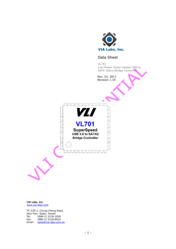
GS2961 3Gb/s, HD, SD SDI Receiver, with Integrated Adaptive Cable Equalizercomplete with SMPTE Video ProcessingKey FeaturesApplications Operation at 2.97Gb/s, 2.97/1.001Gb/s, 1.485Gb/s,1.485/1.001Gb/s and 270Mb/s Supports SMPTE 425M (Level A and Level B), SMPTE424M, SMPTE 292M, SMPTE 259M-C and DVB-ASI Integrated adaptive cable equalizer Application: Single Link (3G-SDI)to Dual Link (HD-SDI) Converter10-bitTypical equalized length of Belden 1694A cable: 150m at 2.97Gb/sHD-SDIGS2962Link AHV F/PCLKGS29613G-SDIHV F/PCLK10-bit 250m at 1.485Gb/sHD-SDIGS2962Link B 480m at 270Mb/s Integrated Reclocker with low phase noise, integratedVCO Serial digital reclocked, or non-reclocked output Ancillary data extraction Optional conversion from SMPTE 425M Level B toLevel A for 1080p 50/60 4:2:2 10-bit Parallel data bus selectable as either 20-bit or 10-bit Comprehensive error detection and correctionfeatures Output H, V, F or CEA 861 Timing Signals 1.2V digital core power supply, 1.2V and 3.3V analogpower supplies, and selectable 1.8V or 3.3V I/O powersupply GSPI Host Interface -20ºC to 85ºC operating temperature range Low power operation (typically 515mW) Small 11mm x 11mm 100-ball BGA package Pb-free and ROHS compliantHD-SDILink AHD-SDIDeserializerGS296110-bit10-bitFIFOHV F/PCLKW3G-SDIRHV F/PCLKHD-SDILink BHD-SDIDeserializerGS2961GS296210-bit10-bitFIFOHV F/PCLKWHV FRGS4910X TALDescriptionThe GS2961 is a multi-rate SDI integrated Receiver whichincludes complete SMPTE processing, as per SMPTE 425M,292M and SMPTE 259M-C. The SMPTE processing featurescan be bypassed to support signals with other codingschemes.ErrataRefer to Errata document entitled GS2960/GS2961 Erratafor this device (document number 53117).GS2961 3Gb/s, HD, SD SDI Receiver, with IntegratedAdaptive Cable EqualizerData Sheet48004 - 2November 2009Application: Dual Link (HD-SDI)to Single Link (3G-SDI) ConverterThe GS2961 integrates Gennum's adaptive cable equalizertechnology, achieving unprecedented cable lengths andjitter tolerance. It features DC restoration to compensate forthe DC content of SMPTE pathological signals.The device features an Integrated Reclocker with aninternal VCO and a wide Input Jitter Tolerance (IJT) of0.7UI.www.gennum.com1 of 104
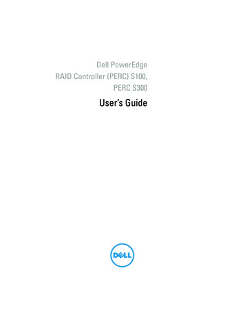
A serial digital loop-through output is provided, which canbe configured to output either reclocked or non-reclockedserial digital data. The serial digital output can be connectedto an external cable driver.The device operates in one of four basic modes: SMPTEmode, DVB-ASI mode, Data-Through mode or Standbymode.Both SMPTE 425M Level A and Level B inputs are supportedwith optional conversion from Level B to Level A for 1080p50/59.94/60 4:2:2 10-bit inputs.In DVB-ASI mode, sync word detection, alignment and8b/10b decoding is applied to the received data stream.In Data-Through mode all forms of SMPTE and DVB-ASIprocessing are disabled, and the device can be used as asimple serial to parallel converter.In SMPTE mode (the default operating mode), the GS2961performs full SMPTE processing, and features a number ofdata integrity checks and measurement capabilities.The device also supports ancillary data extraction, and canprovide entire ancillary data packets throughhost-accessible registers. It also provides a variety of otherpacket detection and error handling features. All of theseprocessing features are optional, and may be individuallyenabled or disabled through register programming.The device can also operate in a lower power Standbymode. In this mode, no signal processing is carried out andthe parallel output is held static.Parallel data outputs are provided in 20-bit or 10-bit formatfor 3Gb/s, HD and SD video rates, with a variety of mappingoptions. As such, this parallel bus can interface directly withvideo processor ICs, and output data can be multiplexedonto 10 bits for a low pin count interface.CrystalBuffer/OscillatorGSPI andJTAG ControllerCORE VDDCORE GNDIO VDDIO GNDDVB ASIRESET TRSTSTANDBYIOPROC EN/DISSMPTE BYPASS20BIT/10BITTIM861SW ENSDIN TDISCLK TCLKCS TMSSDOUT TDOJTAG/HOSTXTAL OUTXTAL1XTAL2VCO VDDVCO GNDPLL VDDPLL GNDFunctional Block DiagramHostInterfaceVBGLB altoParallelConverterDescramble,Word Align,Rate tractionANC/Checksum/352MExtractionSMPTE 425MLevel BLevel A1080p 50/604:2:2 10-bitIllegal coderemap,TRS/Line Number/CRSInsertion,EDH PacketInsertionPCLKOutput Mux/DemuxDOUT[19:0]MuxAGC AGCV/VSyncH/HSyncLOCKEDError FlagsF/DeMuxYANC/CANCBufferRate det[1:0]DVB-ASIDecoderSDOSDOLOCKEDEQ VDDEQ GNDA VDDA GNDBUFF VDDBUFF GNDRC BYPSDO EN/DISI/O ControlGS2961 Functional Block DiagramGS2961 3Gb/s, HD, SD SDI Receiver, with IntegratedAdaptive Cable EqualizerData Sheet48004 - 2November 20092 of 104
Revision HistoryVersionECRPCNDate215314353865November 20091152698–October 2009Updated Power numbers in Table 2-3:DC Electrical Characteristics.0151888–June 2009Conversion to Preliminary Data Sheet.Corrections to Timing Diagrams inFigure 4-5, Figure 4-6 and Figure 4-7.Clarification to Section 4.18.8. Updatesto all sections.C151697–April 2009Updated equalized cable lengths andpower numbers in Key Features, Table2-4: AC Electrical Characteristics andSection 4.3.1.B151504–March 2009Changed pin H3 from ‘RSV’ to‘CORE GND’ in 1.1 Pin Assignment, 1.2Pin Descriptions and 5.3 TypicalApplication Circuit.A151219–February 2009GS2961 3Gb/s, HD, SD SDI Receiver, with IntegratedAdaptive Cable EqualizerData Sheet48004 - 2November 2009Changes and/or ModificationsAdded reference to GS2960/GS2961Errata (document number 53117).Converted to Data Sheet.New Document.3 of 104
ContentsKey ional Block Diagram .2Revision History .31. Pin Out.81.1 Pin Assignment .81.2 Pin Descriptions .82. Electrical Characteristics . 152.1 Absolute Maximum Ratings . 152.2 Recommended Operating Conditions . 152.3 DC Electrical Characteristics . 162.4 AC Electrical Characteristics . 183. Input/Output Circuits . 234. Detailed Description. 274.1 Functional Overview . 274.2 SMPTE 425M Mapping - 3G Level A and Level B Formats . 284.2.1 Level A Mapping. 284.2.2 Level B Mapping . 284.3 Serial Digital Input . 294.3.1 Integrated Adaptive Cable Equalizer. 294.4 Serial Digital Loop-Through Output . 304.5 Serial Digital Reclocker . 304.5.1 PLL Loop Bandwidth . 314.6 External Crystal/Reference Clock . 324.7 Lock Detect . 334.7.1 Asynchronous Lock . 334.7.2 Signal Interruption. 344.8 SMPTE Functionality . 344.8.1 Descrambling and Word Alignment . 344.9 Parallel Data Outputs . 354.9.1 Parallel Data Bus Buffers. 354.9.2 Parallel Output in SMPTE Mode . 384.9.3 Parallel Output in DVB-ASI Mode . 384.9.4 Parallel Output in Data-Through Mode . 394.9.5 Parallel Output Clock (PCLK). 394.9.6 DDR Parallel Clock Timing . 404.10 Timing Signal Generator . 414.10.1 Manual Switch Line Lock Handling. 424.10.2 Automatic Switch Line Lock Handling . 434.10.3 Switch Line Lock Handling During Level B to Level A Conversion . 44GS2961 3Gb/s, HD, SD SDI Receiver, with IntegratedAdaptive Cable EqualizerData Sheet48004 - 2November 20094 of 104
4.11 Programmable Multi-function Outputs . 464.12 H:V:F Timing Signal Generation . 474.12.1 CEA-861 Timing Generation . 494.13 Automatic Video Standards Detection . 564.14 Data Format Detection & Indication . 594.15 EDH Detection . 604.15.1 EDH Packet Detection . 604.15.2 EDH Flag Detection . 614.16 Video Signal Error Detection & Indication . 614.16.1 TRS Error Detection. 634.16.2 Line Based CRC Error Detection . 634.16.3 EDH CRC Error Detection. 644.16.4 HD & 3G Line Number Error Detection . 644.17 Ancillary Data Detection & Indication . 644.17.1 Programmable Ancillary Data Detection. 664.17.2 SMPTE 352M Payload Identifier . 674.17.3 Ancillary Data Checksum Error . 684.17.4 Video Standard Error. 694.18 Signal Processing . 694.18.1 TRS Correction & Insertion. 704.18.2 Line Based CRC Correction & Insertion . 714.18.3 Line Number Error Correction & Insertion . 714.18.4 ANC Data Checksum Error Correction & Insertion . 714.18.5 EDH CRC Correction & Insertion . 714.18.6 Illegal Word Re-mapping . 724.18.7 TRS and Ancillary Data Preamble Remapping. 724.18.8 Ancillary Data Extraction. 724.18.9 Level B to Level A Conversion . 774.19 GSPI - HOST Interface . 774.19.1 Command Word Description . 784.19.2 Data Read or Write Access. 794.19.3 GSPI Timing. 804.20 Host Interface Register Maps . 824.21 JTAG Test Operation . 954.22 Device Power-up . 974.23 Device Reset . 974.24 Standby Mode . 975. Application Reference Design . 985.1 High Gain Adaptive Cable Equalizers . 985.2 PCB Layout . 985.3 Typical Application Circuit . 996. References & Relevant Standards . 1007. Package & Ordering Information . 1017.1 Package Dimensions . 1017.2 Packaging Data . 102GS2961 3Gb/s, HD, SD SDI Receiver, with IntegratedAdaptive Cable EqualizerData Sheet48004 - 2November 20095 of 104
7.3 Marking Diagram . 1027.4 Solder Reflow Profiles . 1037.5 Ordering Information . 103List of FiguresFigure 3-1: Digital Input Pin with Schmitt Trigger. 23Figure 3-2: Bidirectional Digital Input/Output Pin. 23Figure 3-3: Bidirectional Digital Input/Output Pin with programmable drive strength. 24Figure 3-4: XTAL1/XTAL2/XTAL-OUT . 24Figure 3-5: VBG . 25Figure 3-6: LB CONT . 25Figure 3-7: Loop Filter . 25Figure 3-8: SDO/SDO . 26Figure 3-9: Equalizer Input Equivalent Circuit . 26Figure 4-1: Level A Mapping . 28Figure 4-2: Level B Mapping . 28Figure 4-3: GS2961 Integrated EQ Block Diagram . 30Figure 4-4: 27MHz Clock Sources . 32Figure 4-5: PCLK to Data and Control Signal Output Timing - SDR Mode 1 . 35Figure 4-6: PCLK to Data and Control Signal Output Timing - SDR Mode 2 . 36Figure 4-7: PCLK to Data and Control Signal Output Timing - DDR Mode . 37Figure 4-8: DDR Video Interface . 40Figure 4-9: Delay Adjustment Ranges . 41Figure 4-10: Switch Line Locking on a Non-Standard Switch Line . 43Figure 4-11: H:V:F Output Timing - 3G Level A and HDTV 20-bit Mode . 47Figure 4-12: H:V:F Output Timing - 3G Level A and HDTV 10-bit Mode3G Level B 20-bit Mode, each 10-bit stream . 47Figure 4-13: H:V:F Output Timing - 3G Level B 10-bit Mode . 48Figure 4-14: H:V:F Output Timing - HD 20-bit Output Mode . 48Figure 4-15: H:V:F Output Timing - HD 10-bit Output Mode . 48Figure 4-16: H:V:F Output Timing - SD 20-bit Output Mode . 48Figure 4-17: H:V:F Output Timing - SD 10-bit Output Mode . 48Figure 4-18: H:V:DE Output Timing 1280 x 720p @ 59.94/60 (Format 4) . 50Figure 4-19: H:V:DE Output Timing 1920 x 1080i @ 59.94/60 (Format 5) . 51Figure 4-20: H:V:DE Output Timing 720 (1440) x 480i @ 59.94/60 (Format 6&7) . 52Figure 4-21: H:V:DE Output Timing 1280 x 720p @ 50 (Format 19) . 52Figure 4-22: H:V:DE Output Timing 1920 x 1080i @ 50 (Format 20) . 53Figure 4-23: H:V:DE Output Timing 720 (1440) x 576 @ 50 (Format 21 & 22) . 54Figure 4-24: H:V:DE Output Timing 1920 x 1080p @ 59.94/60 (Format 16) . 54Figure 4-25: H:V:DE Output Timing 1920 x 1080p @ 50 (Format 31) . 55Figure 4-26: H:V:DE Output Timing 1920 x 1080p @ 23.94/24 (Format 32) . 55Figure 4-27: H:V:DE Output Timing 1920 x 1080p @ 25 (Format 33) . 56Figure 4-28: H:V:DE Output Timing 1920 x 1080p @ 29.97/30 (Format 34) . 56Figure 4-29: Y/1ANC and C/2ANC Signal Timing . 66Figure 4-30: Ancillary Data Extraction - Step A . 73Figure 4-31: Ancillary Data Extraction - Step B . 74Figure 4-32: Ancillary Data Extraction - Step C . 75Figure 4-33: Ancillary Data Extraction - Step D . 76GS2961 3Gb/s, HD, SD SDI Receiver, with IntegratedAdaptive Cable EqualizerData Sheet48004 - 2November 20096 of 104
Figure 4-34: GSPI Application Interface Connection . 78Figure 4-35: Command Word Format . 78Figure 4-36: Data Word Format . 79Figure 4-37: Write Mode . 80Figure 4-38: Read Mode . 80Figure 4-39: GSPI Time Delay . 80Figure 4-40: In-Circuit JTAG . 95Figure 4-41: System JTAG . 96Figure 4-42: Reset Pulse . 97Figure 7-1: Pb-free Solder Reflow Profile . 103List of TablesTable 1-1: Pin Descriptions . 8Table 2-1: Absolute Maximum Ratings. 15Table 2-2: Recommended Operating Conditions. 15Table 2-3: DC Electrical Characteristics . 16Table 2-4: AC Electrical Characteristics . 18Table 4-1: Serial Digital Output. 30Table 4-2: PLL Loop Bandwidth . 31Table 4-3: Input Clock Requirements. 32Table 4-4: Lock Detect Conditions. 33Table 4-5: GS2961 Output Video Data Format Selections. 37Table 4-6: GS2961 PCLK Output Rates . 39Table 4-7: Switch Line Position for Digital Systems . 44Table 4-8: Output Signals Available on Programmable Multi-Function Pins. 46Table 4-9: Supported CEA-861 Formats. 49Table 4-10: CEA861 Timing Formats. 50Table 4-11: Supported Video Standard Codes . 57Table 4-12: Data Format Register Codes . 60Table 4-13: Error Status Register and Error Mask Register . 62Table 4-14: SMPTE 352M Packet Data . 68Table 4-15: IOPROC DISABLE Register Bits. 70Table 4-16: GSPI Time Delay. 80Table 4-17: GSPI Timing Parameters (50% levels; 3.3V or 1.8V operation) . 81Table 4-18: Configuration and Status Registers. 82Table 4-19: ANC Extraction FIFO Access Registers. 94Table 7-1: Packaging Data. 102GS2961 3Gb/s, HD, SD SDI Receiver, with IntegratedAdaptive Cable EqualizerData Sheet48004 - 2November 20097 of 104
1. Pin Out1.1 Pin Assignment12AVBGLFBA VDDCDE345678910LB CONTVCOVDDSTAT0STAT1IO VDDPCLKPLLVDDRSVVCOGNDSTAT2STAT3 IO GND DOUT19 DOUT16 DOUT15SDIA GNDPLLVDDPLLVDDSTAT4STAT5RESETDOUT12 DOUT14 DOUT13TRSTSDIA GNDA GNDPLLGNDCOREGNDCOREVDDSW ENEQ VDD EQ GND A GNDPLLGNDCOREGNDCOREVDDSDOUT SDINTDOTDIDOUT18 DOUT17JTAG/IO GND IO VDDHOSTDOUT10 DOUT11FAGCPA GNDPLLGNDCOREGNDCOREVDDGAGCN A GND RC BYPCOREGNDCOREGNDCOREVDDSMPTEDVB ASI IO GND IO VDDBYPASSHBUFFVDDBUFFGNDCOREGNDRSVTIM 861XTALOUT20bit/ IOPROCDOUT6 DOUT710bitEN/DISJSDOSDOEN/DISRSVRSVRSVXTAL2 IO GND DOUT1 DOUT4 DOUT5KSDOSTANDBYRSVRSVRSVXTAL1 IO VDD DOUT0 DOUT2 DOUT3RSVCSTMSSCLKTCKDOUT8 DOUT91.2 Pin DescriptionsTable 1-1: Pin DescriptionsPinNumberNameTimingTypeA1VBGAnalog InputBand Gap voltage filter connection.A2LFAnalog InputLoop Filter component connection.A3LB CONTAnalog InputConnection for loop bandwidth control resistor.A4VCO VDDInput PowerPOWER pin for the VCO. Connect to 1.2V DC analog through an RCfilter (see 5. Application Reference Design). VCO VDD is nominally0.7V. (Do not connect directly to 0.7V).GS2961 3Gb/s, HD, SD SDI Receiver, with IntegratedAdaptive Cable EqualizerData Sheet48004 - 2November 2009Description8 of 104
Table 1-1: Pin Descriptions (Continued)PinNumberNameA5, A6, B5,B6, C5, ONAL OUTPUT PORT.Signal levels are LVCMOS/LVTTL compatible.Each of the STAT [0:5] pins can be configured individually to outputone of the following CC/2ANCDATA ERROREDH DETECTEDCARRIER DETECTRATE DET0RATE DET1A7, D10,G10, K7IO VDDInput PowerA8PCLKOutputGS2961 3Gb/s, HD, SD SDI Re
GS2961 3Gb/s, HD, SD SDI Receiver, with Integrated 1 of 104 Adaptive Cable Equalizer Data Sheet 48004 - 2 November 2009 GS2961 3Gb/s, HD, SD SDI Receiver, with Integrated Adaptive Cable Equalizer complete with SMPTE Video Processing www.gennum.com Key Features Operation at 2.97Gb/s, 2.97/1.001Gb/s, 1.485Gb/s, 1.485/1.001Gb/s and 270Mb/s