Transcription
Pave Israel 96IS THE USE OF CONCRETEBLOCK PAVING FINITEC. LuidensHeidemij Advies, Regio WestRotterdam, The NetherlandsJ.G. Van HeesEurope Combined Terminals B.V.The NetherlandsSummaryEurope Combined Terminals (BCT) have successfully used concrete block paving in theircontainer terminals for many years.Dozens of hectares are surfaced with this type of material every year. Recently, however, ECThave been faced with rutting where Automated Guided Vehicles are used. The RotterdamMunicipal Port Management and ECT asked Heidemij Advies to conduct a study into the causeof the problems and to recommend ways to resolve them.The study has been completed and a number of modifications to the surfacing have beenproposed. These modifications related to: the shape of the concrete blocks; the thickness of the surface layer; the composition of the foundation.The modifications have meanwhile been carried out and the redesigned surfacing structure isbeing used for ECT's new expansions in Rotterdam.The paper describes the problem and looks in detail at the modifications to the concrete blockpaving.IutroductiouEurope Combined Terminals (ECT) have used concrete block paving as a surfacing material intheir container terminals for some thirty years. Altogether some four million square metres havebeen surfaced in this way.Concrete block paving has proved it can withstand the heavy point loads associated withcontainers, as well as the high wheel loads and large torsional forces exerted by the transporters.Concrete block paving also appears to be able to adjust to significant settlement, and it is easyto reuse when there is reconstruction. All in all concrete paving is an excellent surfacing materialfor heavily-loaded container terminals.However it is not just the concrete paving which provides such good performance. Foundationsare required underneath the paving in order to transmit heavy loads to the subsoil properly.Recently, however, ECT have been faced with rutting in their terminal where Automated GuidedVehicles are used.Heidemij Advies was asked to conduct a study into the cause of the problems and to recommendways to resolve them. This paper reports on the use of concrete paving at ECT over the last thirtyyears, the onset of rutting, the investigation into this phenomenon and the proposed modificationsto the surfacing.Finally the future prospects for concrete block paving are discussed.473
ECT and concrete block pavingECT is a stevedoring company that deals primarily with containers.They a re one of the largest container handling companies in the wo rld, and number one inEurope (table I and 2).'IT OP 10 CONTAI NERPORTS N-W EUROP §i994ITOP 10 WORLD CONTAINER PORTS:IIIi99A1234567891012345678910TEU11 ,265 ,000106000004 899 ,0004,475 ,00037500002,787,0002725 ,00025730002,5 18,0002,320000Hong g Bea chLos Ang e en/BremerhafenLe HavreZeebruggeSouthamptonGothenburgTilburvTotalECT totalTEUI4 609000587000401 ,00038200015,601 ,0003,390,000 ITable 2Table 1ECT is located in Rotterdam, Europe's most important main port. An area was recently reclaimedfrom the sea at the entrance to the port of Rotterdam and turned into dry land.Rotterdam Municipal Port Management and ECT are working together in this area to developlarge-scale container terminals with deep-water access. Containers are brought to and from theterminal by enormous ocean-go ing container carriers.Huge dock cranes a re used to handle the containers, and onward transport is by feeder , barge,rail or road .Special transporters such as Straddle Carriers, Multi Trailer Systems and Automated GuidedVehicles are used in the termina ls.There the total moves of containers is growing rapidly (fig. I), concrete block paving is againbeing used for su rfacing the newest terminals.J-- --- - -- ---m,,m.,-- -- - - - - ITEU movesFigure I474[DCo ntainer l11 0ves,
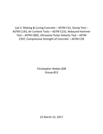
First-generation terminalIn 1967 the growth in container transport prompted ECf to start building their first-generationterminal , the Home Terminal, in Rotterdam (fig. 2).Figure 2Home TerminalThe site where activities started was covered with a layer of sand from the sea bed, below whichwas a layer of harbour silt with poor load-bearing capacity, and below that a peat/day subsoil.The transport of containers in the terminal was done primarily using trailers with tractors andstraddle carriers. The latter had wheel loads of between 125 kN and 170 kN. Heidemij designeda surface for this poor load-bearing subsoil comprising concrete block paving on a granularintermediate layer, with a foundation of sand cement stabilization.The concrete block paving showed that it could withstand the high contact pressures of thecontainers (comer castings) and the large torsional forces caused by the rotation of the straddlecarriers' wheels . A foundation was made underneath the concrete block paving comprising sandcement stabilization ('mix in place') about 330 mm thick. The surfacing was able to follow largedegrees of settlement more than 1.5 metres in some cases, and it fully satisfied the requirementsset.This was reported in a contribution to the First International Conference on Concrete BlockPaving in 1980 [I].The concrete blocks were approximately 220 mm long, 110 mm wide and 120 mm thick(specifications by NEN 7000) and was laid by hand.475
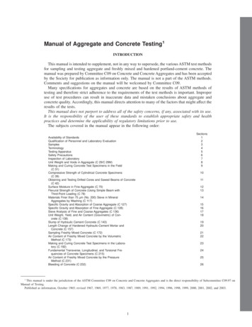
Second-generation terminalIn 1980 ECT decided to expand their activities by building on the Maasvlakte, an area at themouth of the port of Rotterdam reclaimed from the sea.The construction of the Delta Multi-Users Terminal (DMU) (fig. 3), covering an area of some80 hectares, enabled the company to handle container carriers with a deep draught. The numberof containers moves was still growing.Figure 3Delta Multi- Users TerminalGenerally speaking, the subsoil on the Maasvlakte is made up of sand with good load-bearingcapacity. Containers are transported by Straddle Carriers, Multi-Trailer Systems and Frontlifttrucks, and wheels loads vary between 100 leN and 200 leN.Prior to the construction of the DMU Terminal, an extensive review was made of the surfacingthat had been used up to that point.Although no major settlement was expected on the Maasvlakte, concrete block paving on afoundation of sand cement stabilization was chosen once again. This was mainly because thesurfacing had proved its worth in the Home Terminal(s), and also because compared with othersurfacing, concrete block paving was cheaper. Furthermore it had been discovered that othertypes of surfacing (asphalt for instance) were soon damaged by the high contact pressures of thecorner castings and were susceptible to damage from oil spills.Despite a subsoil with a higher load-bearing capacity, the DMU Terminal required a thickerfound ation than in the Home Terminal (about 450 mm) because of the increase in wheel loadsand the higher frequency of container movements.Those days the requirements set for the sand cement stabilization were:a compressive strength of at least 2 MPa after 28 days' setting;rejected if the compressive strength is 1.5 MPa after 28 days' setting.A granular intermediate layer was put on the stabilization and the concrete block paving was laidon this layer.476
Mechanical pavement laying was developed in the nineteen-eighties, and concrete block pavingwas laid one square metre at a time (fig. 4) (Specificatio n by NEN 7000, but a 10 mm sharpertolerance).Figure 4One square metre at a timeWhen being laid mechanically, the blocks were placed very close together and the upper edges ofthe concrete blocks could get damaged. The concrete blocks were given 'spacers' in order toensure the joints were wide enough (fig. 5).0//,/ ////b1sFigure 5 Type of concrete block paving suitable for mechanical pavement laying477
The overall structure of the surfacing was as follows (fig. 6):120 concrete blocksI .J;;trr50 granular material450 sand cementstabilizationsand subsoilFigure 6Third-generation terminalECT took a big step forwards in 1990 with the construction of the third-generation terminal, theDelta SeaLand Terminal (DSL) (fig. 7).Figure 7Delta SeaLand TerminalVirtually everything is automated in this DSL Terminal. On the sea side, the containers aretransported by Automated Guided Vehicles (AGVs) and stacked by Automated Stacking Cranes.Straddle Carriers and Frontlift trucks are used on the shore side.During the preparatory phase of the DSL Terminal it was established that the increasing load andfrequency of transport movements could cause problems in terms of the required foundationthickness. The thickness of the sand cement stabilization needed was becoming ever greater andrecommendations were made to start an investigation into how to optimize the foundation. Thefoundation had grown in the meantime to a thickness of 550 mm, and it had reached themaximum thickness ('mix in place') which could be laid in one pass.478
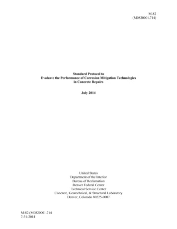
At the DSL Terminal, ECT were soon faced with rutting in the surfacing. This rutting occurredin areas where AGVs are used.The AGVs move over the surfacing along fixed routes using a set pattern of guide points whichhave been installed in the surfacing.The AGVs are not sprung and they have hydraulic drive and braking systems. The maximumwheel loads (aircraft wheels) are 130 kN (fig. 8).Figure 8Automated Guided VehicleFirst of all the pattern in which the blocks were laid was examined to see if it had any effect onthe rutting [2).However, no indication was found that the way the paving is laid has any influence on rutting,and the herringbone bond is still preferred.It was decided to investigate the cause of the rutting and to draw up recommendations forimproving the surfacing before the construction of a number of new terminals (the 2000-8 plan).The investigation showed clearly that the rutting occurred primarily in the topmost part of thesand cement stabilization.A number of causes of the damage were identified, such as:loose material in the topmost layer (sods/scrapings) that is created when re-proflling thesand cement stabilization,loose material that is created through over-compaction (sod formation/segregation),drying out of the upper surface,pulverization of the topmost layer,ingress of moisture (softening),possible ingress of frost.A laboratory investigation was started into improving the resistance of the upper surface of thefoundation to damage ('wear resistance'), with the solution being sought in the addition of acoarse fraction to the topmost centimetres of the sand cement stabilization.479
Plan 2000-8In 1994 the Rotterdam Municipal Port Management together with ECf, started work on the2000-8 plan for the construction of a number of terminals for megacarriers in the tbirdmillennium.Heidemij was involved once more in the construction of tbe infrastructure both above and belowthe surface, a job that will probably continue until 2003 and tbe first pbase of which is underconstruction (fig. 9).Figure 9Plan 2000-8 Phase 1Tbe laboratory investigation into improving the sand cement stabilization showed that additionof a coarse fraction made mixtures less prone to pulverization and frost and gave them asignificantly higber density and compressive strength than mixtures that did not have this fractionadded to them .In the end a mixture was proposed for tbe topmost layer of the foundation with a 50% coarsefraction, made up of concrete rubble and 50% sand, all mixed together with cement. A so called'modified' sand cement stabilization. A layer of 0-20 mm concrete rubble was put directly on topof the sand cement stabilization and this layer was mixed with the top 100 mm of the fresh sandcement stabilization ('mix in place') to yield at the end of the process, after compaction, a 200 mmlayer of 'modified' sand cement stabilization.480
As well as the foundation modifications described above, it was also proposed to reduce thethickness of the granular intermediate layer between the concrete blocks and the foundation inorder to reduce the chance of possible post-compaction in this layer.Although the granular intermediate layer could possibly have some effect, it is not believed to bethe actual cause of the rutting.To be on the safe side, however, the thickness of the layer has been reduced from 50 mm to 30mm, and the layer is put on mechanically using a spreading machine.The chippings 0-8 mm for the granular layer must comply with the following specification:screenweight percent retainedmin.max.mesh sizeC8C 5.62mm63 11m0102040608010090Table 3The thinner, intermediate layer meant that the tolerances of the concrete blocks had to beadjusted. These are now plus or minus 2 mm. The concrete block paving is vibrated and sharpsand is used to fill the joints.The sand used for brushing into the joints between the concrete blocks must comply with thefollowing specification:weight percent retainedscreenmin.max.mesh sizeC 5.6C41 mm63 !-Lm010901045100Table 4Furthermore the drainage slopes on the site were modified and the surface drainage wasimproved. More holes were drilled in the foundation in order to allow water on the foundationsto drain away to the subsoil/drainage more quickly.All these changes have been implemented in the meantime and the total design is being evaluated.In addition to improvements in the surfacing, the means of transport are also being evaluated.There is always an interaction between these two aspects. For example, a study is currently underway to see if the AGVs could be equipped with double pneumatic tyres andlor could be fittedwith springs. A review is also being made to see if the AGVs could move over a wider area ofthe site, and therefore less along fixed paths.482
Is the use of concrete block paving finiteThe suitability of the preseut surfacing design is being evaluated prior to the construction of thenew terminal (T2), which is part of the 2000-8 plan. Both technical and financial aspects areincluded (fig. 12).100 . --, ----- --------- -. ----------- - 80 60c .g 4020. L.l I!1---.--J . .L. L L,, l lI L !II!I!I!L.L.l 8619881990199219941996-- - .- - . .:::-:::: --.-----[.; sewerage Idrai ge. stabilisation:*-concrete block pavingFigure 12Although the concrete block paving performs well as such, it has been shown that the capabilitiesof the foundation could limit the further use of concrete block paving.An investigation has started again into the possibilities offered by other surfacing materials, forexample:high-stability asphalt concrete;roller-compacted concrete;reinforced concrete;etc.Needless to say, improvement of the surfacing through the use of modified sand cementstabilization is being pursued as an answer to the problem of rutting. It will be clear, however,that changes to the foundation also have financial consequences.The answer to the question, 'is the use of concrete block paving finite?' will ultimately bedetermined by the price of the overall surfacing design.LiteratureI.Van Leeuwen, H.2.Bouman, S.R. e.a."Use of block paving in European ports.""The influence of different types of block pavement on the(un)evenness of the surface of the world's Jarge§t containerterminal. "483
BLOCK PAVING FINITE C. Luidens Heidemij Advies, Regio West Rotterdam, The Netherlands J.G. Van Hees Europe Combined Terminals B.V. The Netherlands Europe Combined Terminals (BCT) have successfully used concrete block paving in their container terminals for many years. Dozens of hectares are surfaced with this type of material every year.