Transcription
Data SheetVL701Low-Power Super-Speed USB toSATA 3Gb/s Bridge ControllerNov. 23, 2011Revision 1.10VIA Labs, Inc.www.via-labs.com7F, 529-1, Chung-Cheng Road,Hsin-Tien, Taipei, TaiwanTel:(886-2) 2218-1838Fax:(886-2) 2218-8924Email: sales@via-labs.com.tw-1-
VL701 Low-Power Super-Speed USB to SATA 3Gb/s Bridge ControllerRevision HistoryRevDateInitialNote0.611/25/2010HCInitial external release0.7512/23/2010HCAdded QFN-48 package1.0002/25/2011HCAdded QFN-48 6x6mm mechanical specAdded GPO pad driving specAdded USB-IF certified TID1.1011/23/2011HCAdded QFN-44 6x5mm package-2-
VL701 Low-Power Super-Speed USB to SATA 3Gb/s Bridge ControllerTable of ContentsRevision History . 2Table of Contents . 3List of Figures . 3List of Tables . 3Product Features . 4VL701 System Overview . 5Pinout. 6Pin List . 9Pin Descriptions . 12Signal Type Definition . 12Serial ATA Interface . 12USB 3.0 Interface . 12USB 2.0 Interface . 12Serial EEPROM Interface. 13Analog Command Block . 13General Purpose I/O and Miscellaneous . 14Test Pin . 14Power and Ground . 14Electrical Specification . 15Package Mechanical Specifications. 21Package Top Side Marking . 24List of igure12345678––––––––VL701 Block Diagram . 5VL701 LQFP-64 Pin Diagram. 6VL701 QFN-48 Pin Diagram . 7VL701 QFN-44 Pin Diagram . 8LQFP 64L 7x7x1.4 mm Mechanical Specification . 21QFN 48L 6x6x0.85 mm Mechanical Specification . 22QFN 44L 6x5x0.85 mm Mechanical Specification . 23Package Top Side Marking . 24List of TablesTable 1 – VL701 LQFP-64 Pin List. 9Table 2 – VL701 QFN-48 Pin List . 10Table 3 – VL701 QFN-44 Pin List . 11-3-
VL701 Low-Power Super-Speed USB to SATA 3Gb/s Bridge ControllerProduct FeaturesVL701Low-Power Super-Speed USB to SATA 3Gb/s Bridge ControllerSuper-Speed USB (5Gb/s) and High-Speed USB (480Mb/s)– Compliant to Universal Serial Bus 3.0 Specification Revision 1.0– Compliant to Universal Serial Bus Specification Revision 2.0– Mass Storage Class Bulk-Only Transport (BOT)– USB Attached SCSI Protocol (UASP) for streaming– Integrated in-house Super-Speed PHY and USB2.0 PHYSerial ATA 3Gb/s and 1.5Gb/s– Compliant to Serial ATA Specification Revision 2.6– Integrated in-house SATA 3Gb/s PHY– RBC command conversion for ATA device– MMC-2 command pass-through to ATAPI– Support 48-bit LBA– Support multiple LUNFast 8051 Macro cell 80C32-Compatible Microcontroller– Standard 1T 8051 instruction setBuilt-in Voltage Regulators– 5.0V to 3.3V LDO– 5.0V to 1.5V switching DC-DCGPIOs for Special Function Usage– 11 GPIOs in LQFP64 and 7 GPIOs in QFN48 for special usage– 2 dedicated BUSY/POWER LED indicators Misc– Support– Support– Support– Supportdevice power down functionexternal SPI flash for firmware upgradeEEPROM for customized PID/VID/SN F/W based capacity LEDs (LQFP64 only)Software– Support Microsoft Windows 7, Vista, XP, 2003, 2000, and ME– Support Mac OS 10.X– Support various Linux kernelsPhysical– LQFP 64L green package (7x7x1.4 mm)– QFN 48L green package (6x6x0.85 mm)– QFN 44L green package (6x5x0.85 mm)Certification–USB-IF SuperSpeed Certified: TID 340760003-4-
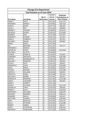
VL701 Low-Power Super-Speed USB to SATA 3Gb/s Bridge ControllerVL701 System OverviewVIA Lab’s VL701 is a high performance, low power single chip USB 3.0 to SATA 3Gb/s bridge controllerdesigned for new generation external storage devices that connecting Hard Disk Drive (HDD), Solid-StateDrive (SSD), and Optical Disc Drive (ODD). Its integrated in-house USB PHY enables VL701 to run in USBSuper-Speed, High-Speed, and Full-Speed modes. Supporting USB mass storage class Bulk-OnlyTransport (BOT), VL701 based devices can work on Windows 7, Vista, XP, 2003/2000/ME, Mac OS X andvarious Linux kernels without additional driver. Besides Bulk-Only Transport, VL701 also support USBAttached SCSI Protocol (UASP) that allowing mass storage command queuing and out of order datatransfers to further enhance read/write performance. Its integrated in-house SATA 3Gb/s host controllercan work with all SATA based storage devices and can connect at either SATA 3Gb/s or 1.5Gb/sautomatically.Built-in all required linear and switching voltage regulators, highly integrated VL701 work perfectly withsingle power input from USB 5V bus power to save customer BOM cost. 11 GPIO pins are available forpush button, operation LEDs, driverless capacity LEDs, device power down control, and other specialusage. The SPI interface can support external flash for firmware upgrades or additional softwareenhancements. VL701 is available in LQFP 64L (7x7x1.4 mm), QFN 48L (6x6x0.85 mm), and QFN 44L(6x5x0.85 mm) green packages to fit small form-factor design.Figure 1 – VL701 Block Diagram-5-
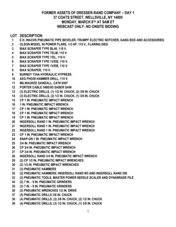
VL701 Low-Power Super-Speed USB to SATA 3Gb/s Bridge ControllerPinoutFigure 2 – VL701 LQFP-64 Pin Diagram-6-
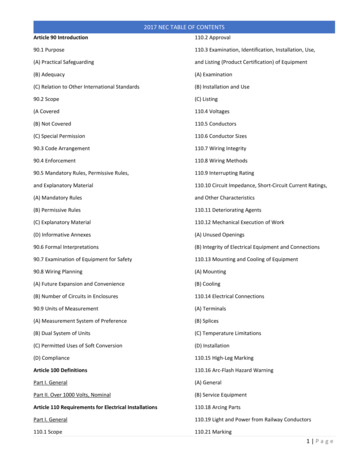
VL701 Low-Power Super-Speed USB to SATA 3Gb/s Bridge ControllerFigure 3 – VL701 QFN-48 Pin Diagram-7-
VL701 Low-Power Super-Speed USB to SATA 3Gb/s Bridge ControllerFigure 4 – VL701 QFN-44 Pin Diagram-8-
VL701 Low-Power Super-Speed USB to SATA 3Gb/s Bridge ControllerPin ListTable 1 – VL701 LQFP-64 Pin ListPinPin NamePinPin USB3TXP56PWRIND25U3TXVDD1557SPI CS26U3RXGND58SPI Q27USB3RXN59SPI CLK28USB3RXP60SPI D29U3RXVDD1561GPIO430U3RXVDD15 162DGND31DGND63VCC3332VCCU64GPIO3-9-
VL701 Low-Power Super-Speed USB to SATA 3Gb/s Bridge ControllerTable 2 – VL701 QFN-48 Pin ListPinPin NamePinPin N44SPI CS21USB3RXP45SPI Q22U3RXVDD1546SPI CLK23U3RXGND47SPI D24VCCU48DGND- 10 -
VL701 Low-Power Super-Speed USB to SATA 3Gb/s Bridge ControllerTable 3 – VL701 QFN-44 Pin ListPinPin NamePinPin YIND18U3TXVDD1540PWRIND19USB3RXN41SPI CS20USB3RXP42SPI Q21U3RXVDD1543SPI CLK22VCCU44SPI D- 11 -
VL701 Low-Power Super-Speed USB to SATA 3Gb/s Bridge ControllerPin DescriptionsSignal Type DefinitionNameTypeSignal DescriptionInputIA standard input-only signalOutputOA standard active driverInput/OutputI/OA bi-directional signalAnalog biasABIASAnalog bias or reference signal. Must be tied to external resistorand/or capacitor bias networkPowerPWRA power pinGroundGNDA ground pinSerial ATA InterfacePin VDD151299PWRAnalog 1.5VSARXVDD15866PWRAnalog 1.5VSARXPI/OSignal DescriptionISATA Port Differential Receive Data 5ISATA Port Differential Receive Data -8OSATA Port Differential Transmit Data 7OSATA Port Differential Transmit Data -SATXGND9——GNDSATA groundSARXGND5——GNDSATA groundLQFP64QFN48QFN44USB 3.0 InterfacePin NameI/OUSB3RXP282120ISignal DescriptionUSB 3.0 Port Differential Receive Data USB3RXN272019IUSB 3.0 Port Differential Receive Data -USB3TXP241817OUSB 3.0 Port Differential Transmit Data USB3TXN231716OUSB 3.0 Port Differential Transmit Data -U3RXVDD15292221PWRAnalog 1.5VU3RXVDD15 130——PWRAnalog 1.5VU3TXVDD15251918PWRAnalog 1.5VU3TXGND22——GNDUSB3 TX groundU3RXGND2623—GNDUSB3 RX 2422PWRAnalog 3.3VVSSU35——GNDUSB2 groundUSB 2.0 InterfacePin NameI/O- 12 -Signal DescriptionUSB 2.0 Bus Data Plus (D )USB 2.0 Bus Data Minus (D–)
VL701 Low-Power Super-Speed USB to SATA 3Gb/s Bridge ControllerSerial EEPROM InterfaceLQFP64QFN48QFN44SPI CS574441OSPI D604744OSerial Flash Data InputSPI Q584542ISerial Flash Data OutputSPI CLK594643OSerial Flash ClockLQFP64QFN48QFN44191413Pin NameI/OSignal DescriptionSerial Flash Chip EnableAnalog Command BlockPin NameOSCXII/OISignal Description25M crystal inputOSCXO201514OREXT141110ABIASConnect to external resistor25M crystal outputLDOVDD5161211PWR5.0V voltage input for 5V to 3.3V LDOLDOVDD33O171312O3.3V voltage output for 5V to 3.3V LDO5.0V voltage input for DC2DC und for DC2DC regulatorDCVSS3349——GNDAnalog ground for DC2DC regulatorDCVDD15FB5037—I1.5V feedback for DC2DC regulator1.5V voltage output for DC2DC , 2110, 1615PWRMaster analog 1.5VMGNDA15, 18——GNDMaster ground- 13 -1.5V voltage input for 1.5V to 1.2V LDO1.2V voltage output for 1.5V to 1.2V LDO
VL701 Low-Power Super-Speed USB to SATA 3Gb/s Bridge ControllerGeneral Purpose I/O and MiscellaneousLQFP64QFN48QFN44BUSYIND554239OBusy LED Indicator, including PWMTypical driving current 12mAPWRIND564340OPower LED Indicator, including PWMTypical driving current 12mARESET544138IExternal Chip ResetGPIO 1333I/OGeneral Purpose I/O (12mA in output mode)Default: Device power down controlGPIO 2222I/OGeneral Purpose I/O, including PWM (12mAin output mode)Default: USB3.0/USB2.0 mode indicatorGPIO 364——I/OGeneral Purpose I/O, including PWM (12mAin output mode)Default: Capacity LED0GPIO 461——I/OGeneral Purpose I/O, including PWM (12mAin output mode)Default: Capacity LED1GPIO 5403028I/OGeneral Purpose I/O (12mA in output mode)Default: Push button trigger pinGPIO 6423230I/OGeneral Purpose I/O (12mA in output mode)Default: USB cable power detectGPIO 7413129I/OGeneral Purpose I/O (12mA in output mode)Default: Device write protect controlGPIO 8392927I/OGeneral Purpose I/O (12mA in output mode)Default: Push button status indicatorGPIO 9372826I/OGeneral Purpose I/O (12mA in output mode)Default: EEPROM chip select & LED blinkingmode selectGPIO 1044——I/OGeneral Purpose I/O (12mA in output mode)Default: Capacity LED2GPIO 1143——I/OGeneral Purpose I/O (12mA in output mode)Default: Capacity LED3LQFP64QFN48QFN44111Pin NameLQFP64QFN48QFN44DGND4, 31, 38,6248—GNDGroundVCC3345, 53,6333, 4031, 37PWRDigital IO power 3.3VVDD12I362725PWRDigital Core power 1.2VPin NameI/OSignal DescriptionTest PinPin NameTESTENI/OISignal DescriptionTest Mode EnableDo not connect for normal operation.Internal pull down.Power and GroundI/O- 14 -Signal Description
VL701 Low-Power Super-Speed USB to SATA 3Gb/s Bridge ControllerElectrical SpecificationAbsolute Maximum RatingSymbolParameterMinMaxUnitTSTGStorage Temperature-55125 CNote—TAAmbient Temperature070 C—VDD33Power Supply Voltage-0.53.69V—VDD50Input Voltage-0.55.5V—VOOutput Voltage at anyoutput-0.5VCC 0.5V—VESDElectrostatic Discharge—2kVHuman Body ModelNote: Stress above conditions may cause permanent damage to the device.Functional operation of this device should be restricted to the conditions described.Operating ConditionsSymbolParameterMinTypMaxVCC33Digital IO power 3.3V3.03.33.6UnitVLDOVDD55V to 3.3V LDO 5V PowerInput4.555.5VDCVDD55V to 1.5V DC2DC 5VPower Input4.555.5VLDOVDD151.5V to 1.2V LDO 1.5VPower Input1.4251.51.65VVDD12IDigital Core power 1.2V1.081.21.36VDGNDGround—0—VGeneral IO DC ut Low Voltage-0.500.8V—VIHInput High Voltage2.0VCC 0.5V—VOLOutput Low Voltage—0.4VIOL -4.0mAVOHOutput High Voltage2.4—VIOH 4.0mAIILInput Leakage Current— /-10µA0 VIN VCCIOZTristate Leakage Current— /-20µA0 VOUT VCCUSB Full Speed DC/AC CharacteristicsSymbolParameterMinVFSIHFull-speed Input High2.0VFSILFull-speed Input LowVFSCMDifferential CommonMode VoltageVFSOLVNote—0.8V—0.82.5V—Full-speed Output Low0.00.3V—VFSOHFull-speed Output High2.83.6V—TFSRFull-speed Rise Time420ns—ns—TFSFFull-speed Fall Time4Max20- 15 -Unit
VL701 Low-Power Super-Speed USB to SATA 3Gb/s Bridge ControllerVFSCRSFull-speed Output SignalCrossover Voltage1.32.0V—USB High Speed DC/AC speed squelchdetection threshold100150mVNote—VHSCMHigh-speed data signalingcommon mode voltage-50500mV—VHSOIHigh-speed idle level-1010mV—VHSOHHigh-speed data high360440mV—VHSOLHigh-speed data low-1010mV—VCHIRPJChirp J level7001100mV—VCHIRPKChirp K level-900-500mV—ZHSDRVDrive output resistance40.549.5Ω—THSRHigh-speed Rise Time500ps—THSFHigh-speed Fall Time500ps—USB Super Speed TX PDifferential p-p Tx swing0.81.2VNote—VTX-DE-RATIOTx de-emphasis3.04.0dB—RTX-DIFF-DCDC differential impedance72120Ω—V—VTX-RCV-DETECTThe Voltage Changeallowed during ReceiverDetectionTTX-EYETransmitter EyeTTX-DJ-DDTx Deterministic JitterRTX-DCTransmitter DC CommonMode ImpedanceVTX-DC-CMTransmitter DC CommonMode VoltageVTX-CM-AC-PP-ACTx AC Common ModeVoltage cal Idle DifferentialP-P Output Voltage010mV—DC Electrical IdleDifferential OutputVoltage010mV—NoteUI does not accountfor SSC causedvariations.DC impedancelimits are needed toguarantee Receiverdetect.Measured withrespect to groundover a voltage of500mV maximum.USB Super Speed RX Characteristics (5.0 GT/s)SymbolParameterMinMaxUnitUIUnit Interval199.94200.06psR RX - DCReceiver DC commonmode impedance1830Ω- 16 -
VL701 Low-Power Super-Speed USB to SATA 3Gb/s Bridge ControllerR RX - DIFF - DCDC differential impedance72ZRX - HIGH - IMP - DC - POS DC Input CM Input25kVRX - LFPS - DET - DIFFp LFPS Detect Threshold100VRX - DIFF - PP - POST - EQ Differential Rx30120ΩΩImpedance for V 0during Reset or powerdown300mVmVpeak-to-peak voltaget RX - TJMax Rx inherent timingerror0.45UIt RX - DJ - DDMax Rx inherentdeterministic timing error0.3UICRX - PARASITICRx input capacitance forreturn loss1.1pfVRX - CM - AC - PRx AC common modevoltage150mVPeakVRX-CM-DC-ACTIVE Rx AC common mode200mVPeakIDLE- DELTA- Pvoltage during the U1 toU0 transitionRx DC CMimpedance with theRx terminations notpowered, measuredover the range 0 –500mv with respectto ground.Below the minimumis noise.Must wake upabove themaximum.Measured after theRx EQ function(Section 6.8.2).Measured after theRx EQ function(Section 6.8.2).Maximum Rxinherentdeterministictiming error.Measured at Rxpins into a pair of50 Ω terminationsinto ground.Includes Tx andchannelconversion, ACrange up to 5 GHz.Measured at Rxpins into a pair of50 Ω terminationsinto ground.Includes Tx andchannelconversion, ACrange up to 5 GHz.SATA TX CharacteristicsSymbolParameterMinMaxUnitZ diffTXTX Pair DifferentialImpedance85115OhmZ s-eTXTX Single-EndedImpedance40RL DD11,TXTX Differential ModeReturn Loss(150MHz-300MHz)14dBTX Differential ModeReturn Loss(300MHz-600MHz)8dBTX Differential ModeReturn Loss(600MHz-1.2GHz)6dB- 17 -Note
VL701 Low-Power Super-Speed USB to SATA 3Gb/s Bridge ControllerTX Differential ModeReturn Loss(1.2GHz-2.4GHz)6dBTX Differential ModeReturn Loss(2.4GHz-3.0GHz)3dBTX Differential ModeReturn Loss(3.0GHz-5.0GHz)1dBTX Common Mode ReturnLoss (150MHz-300MHz)8dBTX Common Mode ReturnLoss (300MHz-600MHz)5dBTX Common Mode ReturnLoss (600MHz-1.2GHz)2dBTX Common Mode ReturnLoss (1.2GHz-2.4GHz)1dBTX Common Mode ReturnLoss (2.4GHz-3.0GHz)1dBTX Common Mode ReturnLoss (3.0GHz-5.0GHz)1dBTX Impedance Balance(150MHz-300MHz)30dBTX Impedance Balance(300MHz-600MHz)20dBTX Impedance Balance(600MHz-1.2GHz)10dBTX Impedance Balance(1.2GHz-2.4GHz)10dBTX Impedance Balance(2.4GHz-3.0GHz)4dBTX Impedance Balance(3.0GHz-5.0GHz)4dBVdiffTXTX Differential OutputVoltage400700mVppdUIVminTXTX Minimum VoltageMeasurement Interval0.450.55UIt 20-80TXTX Rise/Fall Time67136pst skewTXTX Differential Skew20psVcm,acTXTX AC Common ModeVoltage50mVp-pD vdiffOOBOOB Differential Delta25mVD vcmOOBOOB Common Mode Delta50mVR/FbalTX Rise/Fall Imbalance20%AmpbalTX Amplitude Imbalance10%Gen1 TJ at ConnectorData-Data, 5UI0.355UIGen1 DJ at ConnectorData-Data, 5UI0.175UIGen1 TJ at ConnectorData-Data, 250UI0.47UIGen1 DJ at ConnectorData-Data, 250UI0.22UIRL CC11,TXRL DC11,TX- 18 -
VL701 Low-Power Super-Speed USB to SATA 3Gb/s Bridge ControllerGen2 TJ at ConnectorClk-Data, f/ 100.3UIGen2 DJ at ConnectorClk-Data, f/ 100.17UIGen2 TJ at ConnectorClk-Data, f/ 5000.37UIGen2 DJ at ConnectorClk-Data, f/ 5000.19UITJ after CIC, Clk-Data,0.55UI0.35UIBAUDBAUDBAUDBAUDf BAUD / 1667DJ after CIC, Clk-Data,f BAUD / 1667SATA RX CharacteristicsSymbolParameterMinMaxUnitVdiffRXRX Differential InputVoltage240750mVppdt 20-80RXRX Rise/Fall time67136pst skewRXRX Differential Skew50PsVcm, acRXRX AC Common ModeVoltage100mVppdf cm, acRXRX AC Common ModeFrequency200MHzGen1 TJ at Connector,Data-Data, 5UI0.43UIGen1 DJ at Connector,Data-Data, 5UI0.25UIGen1 TJ at Connector,Data-Data, 250UI0.6UIGen1 TJ at Connector,Data-Data, 250UI0.35UIGen2 TJ at Connector,Clk-Data, f/100.46UIGen2 DJ at Connector,Clk-Data, f/100.35UIGen2 TJ at Connector,Clk-Data, f/5000.60UIGen2 DJ at Connector,Clk-Data, f/5000.42UI115Ohm2BAUDBAUDBAUDBAUDZ diffRXRX Pair DifferentialImpedance85RL DD11RX Differential ModeReturn Loss(150MHz-300MHz)18dBRX Differential ModeReturn Loss(300MHz-600MHz)14dBRX Differential ModeReturn Loss(600MHz-1.2GHz)10dB- 19 -Note
VL701 Low-Power Super-Speed USB to SATA 3Gb/s Bridge ControllerRX Differential ModeReturn Loss(1.2GHz-2.4GHz)8dBRX Differential ModeReturn Loss(2.4GHz-3.0GHz)3dBRX Differential ModeReturn Loss(3.0GHz-5.0GHz)1dBRX Common Mode ReturnLoss (150MHz-300MHz)5dBRX Common Mode ReturnLoss (300MHz-600MHz)5dBRX Common Mode ReturnLoss (600MHz-1.2GHz)2dBRX Common Mode ReturnLoss (1.2GHz-2.4GHz)2dBRX Common Mode ReturnLoss (2.4GHz-3.0GHz)2dBRX Common Mode ReturnLoss (3.0GHz-5.0GHz)1dBVthreshOOB Signal DetectionThreshold50200mVppdUI OOBUI During OOB Signaling646.67686.67psCOMINIT/COMRESET/COMWAKE Transmit BurstLength160160UI OOBCOMINIT/COMRESETTransmit Gap Length480480UI OOBCOMWAKE Transmit GapLength160160UI OOBCOMWAKE Gap DetectionWindow55175nsCOMINIT/COMRESET GapDetection Window175525nsRL CC11- 20 -
VL701 Low-Power Super-Speed USB to SATA 3Gb/s Bridge ControllerPackage Mechanical SpecificationsLQFP-64 Pb-free Maximum Temperature for IR ReflowParameterMaximum Temperature TpMax Time within 5 C of TpValue26030Unit CsecondsFigure 5 – LQFP 64L 7x7x1.4 mm Mechanical Specification- 21 -
VL701 Low-Power Super-Speed USB to SATA 3Gb/s Bridge ControllerQFN-48 Pb-free Maximum Temperature for IR ReflowParameterMaximum Temperature TpMax Time within 5 C of TpValue25030Unit CsecondsFigure 6 – QFN 48L 6x6x0.85 mm Mechanical Specification- 22 -
VL701 Low-Power Super-Speed USB to SATA 3Gb/s Bridge ControllerQFN-44 Pb-free Maximum Temperature for IR ReflowParameterMaximum Temperature TpMax Time within 5 C of TpValue25030Unit CsecondsFigure 7 – QFN 44L 6x5x0.85 mm Mechanical Specification- 23 -
VL701 Low-Power Super-Speed USB to SATA 3Gb/s Bridge ControllerPackage Top Side MarkingL6: LQFP64 PackageQ4: QFN48 PackageT4: QFN44 PackageVLIVL701-L6YYWW: Date code(YY Year; WW Week)YYWWTA0XXXXXXXXIdentification CodeA0 XXXXXXXXRevision CodeInternal codeFigure 8 – Package Top Side Marking- 24 -Package substanceT True green
VL701 Low-Power Super-Speed USB to SATA 3Gb/s Bridge ControllerVIA Labs, Inc.www.via-labs.com7F, 529-1, Chung-Cheng Road,Hsin-Tien, Taipei, TaiwanTel:(886-2) 2218-1838Fax:(886-2) 2218-8924Email: sales@via-labs.com.twCopyright 2010 VIA Labs, Inc. All Rights Reserved.No part of this document may be reproduced, transmitted, transcribed, stored in a retrieval system,or translated into any language, in any form or by any means, electronic, mechanical, magnetic,optical, chemical, manual or otherwise without the prior written permission of VIA Labs, Inc. Thematerial in this document is for information only and is subject to change without notice. VIA Labs,Inc. reserves the right to make changes in the product design without reservation and without noticeto its users.All trademarks are the properties of their respective owners.No license is granted, implied or otherwise, under any patent or patent rights of VIA Labs, Inc. VIALabs, Inc. makes no warranties, implied or otherwise, in regard to this document and to the productsdescribed in this document. The information provided by this document is believed to be accurateand reliable as of the publication date of this document. However, VIA Labs, Inc. assumes noresponsibility for any errors in this document. Furthermore, VIA Labs, Inc. assumes no responsibilityfor the use or misuse of the information in this document and for any patent infringements that mayarise from the use of this document. The information and product specifications within this documentare subject to change at any time, without notice and without obligation to notify any person of suchchange.- 25 -
- Compliant to Universal Serial Bus Specification Revision 2.0 - Mass Storage Class Bulk-Only Transport (BOT) - USB Attached SCSI Protocol (UASP) for streaming - Integrated in-house Super-Speed PHY and USB2.0 PHY Serial ATA 3Gb/s and 1.5Gb/s - Compliant to Serial ATA Specification Revision 2.6 - Integrated in-house SATA 3Gb/s PHY