Transcription
l11111111111lI11111United States PatentUS005 149339AC191[illCollins, Jr.1451ROTARY DEVICE FOR REMOVINGPARTICULATES FROM A GAS 34,846,8564,871,515Earl R. Collins, Jr., La Canada, Calif.California Institute of Technology,Pasadena, Calif.Appl. NO.: 667,712Assignee:Filed:Mar.11,1991Int. C l . 5 .B03C 1/00U.S. Cl. .55/6; 55/127;55/152Field of Search .55/127, 152, 6References CitedU.S. PATENT 19756/19781/197910/19807/198210/1982Bradley .55/139Slepian .55/139Streuber .55/139Rommel55/139Boll .55/103Carta et al. .209/11Shriner .%/I03Hudis55/126Vincent .55/123Huang et al. .55/4Schwab et al. .55/107Peterson et al.Stockford et al.Yu et al. .361/229Dietz .55/152Patent Number:Date of 339Sep. 22, 1992Kunsagi .%/I07Long .55/2Taillet et al. .55/107Gilliagham et al. . 55/127Burger et al. .55/106Reichle et al. .422/174PrimaTy Examiner-Bernard NozickAttorney, Agent, or Firm-John J. Posta, Jr.C571ABSTRACTA rotary particulate separator for removing particulatesfrom a pressurized gas stream such as that emanatingfrom a reactor vessel is disclosed which precharges theparticles in the gas stream, and then utilizes the chargeon the particles to induce them from the main flow paththrough an airblock and into the rotary particulate separator. The rotor of the rotary particulate separator haspolarized plates which use a first charge opposite thaton the charged particles to attract the particles as theyenter the rotation chamber, and then use a secondcharge of the same polarity as the charge on thecharged particles to release the particles into a controlgas flow vortex which draws the particles radially inwardly into an exit aperture contained in the center ofone of the rotor segments and out from the device.Pressure letdown devices are used to drop the pressureof both the control gas flow exiting the separator withthe particles and the cleaned gas stream.28 Claims, 6 Drawing Sheets
U.S. PatentSep. 22, 1992Sheet 1 of 65,149,339
U.S. Patent109Sep. 22, 1992Sheet 2 of 65,149,339
US. PatentSep. 22, 199296Sheet 3 of 65,149,339
U.S. PatentSep. 22, 1992Sheet 4 of 65,149,339
U.S. PatentSheet 5 of 6Sep. 22,1992stvVOLTAGEPOWERSUPPLYTOt VtccASH B CONTROL GAS OUT(ATMOSPHERIC PRESSURE)5,149,339
U.S. PatentSep. 22, 1992Sheet 6 of 65,149,339
15,149,339ROTARY DEVICE FOR REMOVINGPARTICULATES FROM A GAS STREAMORIGIN OF THE INVENTION5The invention described herein was made in the performance Of work under a NASAand is subject to the provisions of Public Law 96-517 (35 U.S.C.202) in which the Contractor has elected to retain title.BACKGROUND OF THE INVENTION1. Field of the InventionThe present invention relates generally to a rotaryparticulate separator for removing particulates from a 15Pressurized gas Stream Such as that emanating from areactor vessel, and more Particularly to a Particulateseparator which utilizes a charge placed on particles inthe gas stream first to induce them from the main flowpath into a vortex generator, and then to carry the 20charged particles with a rotor located in the vortexgenerator into a vortex generated by a control gas flowwhich draws the particles radially inwardly into an exitaperture and out from the device.2. Description of Background Information25A wide variety of devices either utilize gas as a working fluid to remove particulates from an operating environment or produce a gaseous stream containing particulates which are released by an operating environment.In either case, a gas stream is produced by a multitude 30of different systems, and that gas stream must becleaned to remove the particulates prior to dischargingthe gas stream into the environment. oneparticularexample of such an operating environment which presentS particular problems is that of a reactor vessel pro- 35ducing a high pressure gas stream containing particulates which must be removed and collected for properdisposal.As might be expected, the art is replete with examplesof devices for removing particulates from a gas stream. 40Most Of theparticulate separators arefilters having a barrier construction which allows gas toflow therethrough. Such mechanical filters are quiteeffective in removing particulates having a sufficiently 45large physical size so as to enable the mechanical filterto trap the particulates. However, in many systems inuse today, including the reactor environment contemplated herein, particulates produced are too fine tobecome trapped in a mechanical filter unless the filter is 50sufficiently small, in which case the particulates tend toquickly clog the filter.Particulates in the reactor environment contemplatedherein have a typical diameter Of approximately two tofive microns, with the gas stream having a typical pres- 55sure Of 300 to 400 PSI. The particulates must be rem e fromdthe high Pressure gas Stream, which emsnates from the reactor vessel on a continuous basis,thereby necessitating continuous processing rather thanbatch processing. Given the particulate size of two to @five microns, the settling rate is from 0.7 to 4.4 inchesper second, as per Stoke's law.A vast number of references exist which utilize various types of electrostatic precipitation. The simplest ofthese devices is the basic electrostatic precipitator 65which places a charge on particulates, and uses electrostatic force to collect them at a collection location in thedevice. Examples of such devices are found in2U.S. Pat. No. 3,400,513, to Boll, in U.S. Pat. No.3,820,306, to Vincent, and in U.S. Pat. No. 4,544,382, toTaillet et al.The Boll patent has a gas stream ducted into and outof a housing, with particulates in the gas stream beingcharged upon entering the housing and collected by aprecipitator. The Vincent device is made of a pluralityof charged plates with dielectric plates (or grids) therebetween, with the dielectric plates receiving inducedand causing precipitation of particles. neTaillet et al. patent uses ion generators to produce spacecharges in an enclosure in which the gas stream containing particulates flows, thus initiating precipitation of theparticulates.me next step in increasing complexity of electrostatic precipitators involves the addition of a filter element to entrap particles drawn into the filter element byelectrostatic force. Devices utilizing this type of construction are illustrated in U.S.Pat. No. 4,339,782, to YUet al., in US. Pat. No. 4,501,598, to Long, and in U.S.Pat. No. 4,871,515, to Reichle et al.The Yu et al. patent illustrates anionizer utilized to charge particulates in a gas stream,with a charged filter element being used to electrostatically attract and contain particulates in the gas stream.The Long reference uses a filter element disposed in thegas flow, with portions of the filter medium fluttering togenerate electrostatic charges to attract and removeParticU!ateS from the gas Stream. The h k h l e et al.patent uses a filter element containing "windshadowareas," which Shield trapped Particles from the gasstream to Prevent them from reentering the gas streamonce trapped in the filter by electrostatic separation.An enhancement to electrostatic separation using afixed filter is illustrated in U.S. Pat. No. 3,783,588, toHudis, and in U.S. Pat. No. 4,229,187, to Stockford et al.In the Hudis patent, moving sheets of filter material arepassed through a gas stream, with electrostatic chargebeing used to attract particulates to the sheets. Thesheets may be cleaned when they are not contained inthe g a stream. The Stockford et al. reference teachesthe use of a filter media which develops an electrostaticcharge in a dry, fast gas stream.Acomplex type of electrostatic precipitator istaught in u.s. Pat. No. 4,093,430,et al., andin u.s. Pat. No. 4,846,430, to Burger et al. These devices charge particles in the gas stream and removethem in a wet process known as 6'scrubbing.99TheSchwab et al. reference uses a dense electrostatic fieldto charge particulates which may then be removed by a%.,,bber.neB et d. patent teaches dispersingscrubbing liquid into the gas stream and then ionizingthe particulates and liquid droplets, which me removedby a high speed brush charged to attract the particulatesand the droplets.Thesedevicesdiscu brieflyaboveareallusefulintheir preferred environments, but are not acceptable forwith the reactor to remove the contaminated particulates in the high pressure gas stream leaving the rattor vessel. The high pressure, continuous flow characteristics of the reactor combined with the necessity forcomplete removal of the particulates present a situationthe devices discussed above are not able to cope with inan acceptable manner.T o date, the only devices which have been even closeto acceptable in particulate removal characteristics arecentrifugal type devices rather than electrostatic filters.Even these devices have not been completely success-
35,149,339ful. Looking once again at the art for further variations,two additional references have been located, both ofwhich combine centrifugal force with electrostatic attraction of particulates. These devices are illustrated inU.S. Pat. No. 4,134,744, to Peterson et al., and in U.S.Pat. No. 4,398,928, to Kunsagi.The Peterson et al. device is designed for an industrialapplication, and has a disk with plural pie-shaped segments through which the gas stream is directed. Alternating segments of the disk are charged with oppositepolarities, and dielectric fluid is supplied to the center ofthe disk. The disk is spun to flow the dielectric fluidradially outwardly, and the charges on the segments ofthe disk attract particulates in the gas stream. The dielectric fluid thus washes particulates attracted to thedisk outwardly, where the charge is neutralized and thefluid, together with the particulates, is collected.While the Peterson et al. device represents an interesting approach, it simply is not suitable for the highpressure reactor application contemplated herein. Theparticulates in the gas stream are not precharged, andsince they are very small, they may well flow throughthe disk and not be removed. In addition, the use of thedielectric fluid creates an additional waste disposalproblem, exacerbating the situation instead of improving it.Finally, the Kunsagi reference teaches a centrifugalseparator using a nozzle directed tangentially to imparta high rotational velocity to the gas stream in a chamber. Electrical charges carried on aerosol charge camers are used to charge small particles, which are thenattracted to the outer walls, where they are carriedaway by the scavenging flow of the larger particles.The Kunsagi reference is designed for removal of particulates generated in combustion of coal, which aremuch larger than the particulates of the applicationcontemplated herein. Thus, none of these referencessuggest a device or method for accomplishing the removal of particulates from a reactor gas stream in asuitable manner.It is accordingly the primary objective of the presentinvention that it operate to remove substantially all ofthe particulates contained in the gas stream emanatingfrom a reactor vessel. Thus, the particulate separator ofthe present invention must be operable on a continuous,high pressure gas stream including particulates to remove the particulates as efficiently as possible. Theparticulate separator must also be operable on the smallparticulates typically contained in a reactor vessel gasstream, which range from approximately two to fivemicrons, and which have small settling rates.It is a further objective of the present invention that itoperate in a manner not requiring a scrubbing fluid, theuse of which would further exacerbate the problem ofsubstance disposal. In addition, the solution to the problems enumerated above should not involve the use of afilter medium, which may become clogged or whichmay require periodic maintenance or changing. It is anadditional objective of the present invention that itoperate to effectively separate the gas in the gas streamfrom Particulates contained therein while using as littlegas as possible.It is a still further objective of the present inventionthat it be relatively compact and inexpensive, both toconstruct, as well as to operate and maintain. The particulate separator of the present invention should alsoenable the conversion of the high pressure gas streamcontaining particulates to a low pressure outlet flow of4gas at a first output point, and a low pressure outflow ofparticulates and a small amount of gas at a second output point. Finally, it is also an objective that all of theaforesaid advantages and objectives be achieved without incurring any substantial relative disadvantage.20253035404550556065SUMMARY O F THE INVENTIONThe disadvantages and limitations of the backgroundart discussed above are overcome by the present invention. With this invention, a particulate separator is disclosed which will separate even very small particlesfrom a high pressure, continuous flow gas stream with ahigh degree of efficiency. As such, the particulate separator of the present invention is suitable for use with areactor vessel to separate the particulates contained inthe gas stream exhausted from the reactor.The particulate separator of the present inventionuses electrostatic principles at two different points inthe separation operation. Prior to arriving at either ofthese two points, the particulates in the gas stream areelectrostatically charged as they pass through a plasmazone in the flow path from the reactor vessel. In thepreferred embodiment, the particulates are all chargedwith a positive charge.The flow path following the charging apparatus includes a particulate removal tube which has a cross-sectional area which smoothly varies from a larger crosssectional area on the inlet end, to a smaller cross-sectional area in the central portion thereof, and back to alarger cross-sectional area on the outlet end. At thelocation of the smallest cross-sectional area in the central portion of the particulate removal tube, there is anaperture opening downwardly into a vortex generator.On the top side of the smallest cross-sectional area in thecentral portion of the particulate removal tube oppositethe aperture leading to the vortex generator is a repelling plate which is charged with the same polarity as thecharge on the particulates (a positive charge in thepreferred embodiment).The charge on the repelling plate forces the chargedparticulates away from the repelling plate as they passthrough the smallest cross-sectional area in the centralportion of the particulate removal tube. The chargedparticulates are thus forced through the aperture in thebottom of the smallest cross-sectional area in the centralportion of the particulate removal tube into the vortexgenerator. The gas stream continues to flow throughthe particulate removal tube toward the outlet endthereof, with the particulates removed. The cleaned gasstream then leaves the particulate removal tube, andflows through a pressure letdown device, at the outletof which the cleaned gas stream exits at atmosphericpressure.The vortex generator comprises a cylindrical chamber which is closed on both ends, with the aperturethrough which the particulates enter the vortex generator being on the side of the cylindrical chamber approximately midway between the two ends and at the topthereof. This top position will be referred to as thetwelve o’clock position. A control gas is supplied tangentially to the vortex generator from the side of thecylindrical chamber at nine o’clock, and flows clockwise in the cylindrical chamber.Two rotating disks are located in the vortex generator parallel to and adjacent the ends of the cylindricalchamber. The area between the two rotating disks,which rotate clockwise, includes the area into whichthe particulates and the control gas flow. As the center
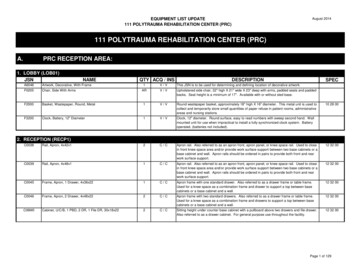
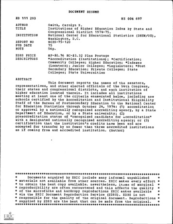
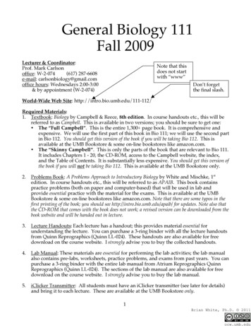
55,149,3396FIG. 1 is an isometric view of a curved electrodeplate;FIG. 2 is a top plan view of the curved electrodeplate shown in FIG. 1;FIG. 3 is an end view of the curved electrode plateshown in FIGS. 1 and 2;FIG. 4 is a side view of an L-shaped electrode;FIG. 5 is a downstream view of the L-shaped e k trode shown in FIG. 4;FIG. 6 is a side view of an insulated, threaded insertfor U s e in mounting the L-shaPd electrode Shown inFIGS. 4 and 5;is aview of the insert shown in6is a Partially cut away side view Of a wentof tubing in which two of the curved electrode platesshown in FIGS. 1 through 3 *aremounted on oppositesides, and in which the L-shaped electrode shown inFIGS. 4 and 5 is mounted using the insert shown inand with the long leg Of the L-shapedplates;trade disposed between the curvedis an end view Of theOf tubing showninfrom the downstream end, showing the flangemounted thereon;FIG. 10 is a plan view of the interior side of a firsthousing half defining half of the particulate removaltube and half of the cylindrical chamber defining thevortex generator,the narrowed central partion ofthe particulate removal tube, the bearing receiving aperture and the shaft aperture in the cylindricalchamber, the split ring commutator for charging conductive segments on the disk of a rotor, and half of thecontrol gaspassageway;FIG. 11is an end view ofthe first housing half shownin FIG. 10 showing the outlet end of the particulateremoval tube and the wiresleading to the split ring commutator;FIG. 12 is a first cross-sectional view of the firsthousing haif shown in FIGS. 10 and 11 showing theaperture between the smallest cross-sectional area in thecentral portion of the particulate removal tube and thecylindrical chamber forming the vortex generator;FIG. 13 is a second cross-sectional view of the firsthousing half shown in FIGS. 10 through 12 also showing the aperture between the smallest cross-sectionalarea in the central portion of the particulate removaltube and the cylindrical chamber forming the vortexgenerator;FIG. 14 is a third cross-sectional view of the firsthousing half shown in FIGS. 10 though 13showing thebearing receiving aperture and the shaft aperture in thecylindrical chamber, and half of the control gas inletpassageway;FIG. 15 is a plan view ofthe interior side o f a secondhousing half defining half of the particulate removaltube and half of the cylindrical chamber defining thevortex generator, showing the narrowed central portion of the particulate removal tube, the bearing receiving aperture and the shaft aperture in the cylindricalchamber, the split ring commutator for charging conductive segments on the disk of a rotor, and half of thecontrol gas inlet passageway;FIG. 16 is an end view of the second housing halfshown in FIG. 15 showing the outlet end of the particulate removal tube and the wires leading to the split ringBRIEF DESCRIPTION OF THE DRAWINGS 65 commutator;These and other advantages of the present inventionFIG. 17 is an isometric view of a curved electrodeare best understood with reference to the drawings, inplate for mounting in the smallest cross-sectional area inthe central portion of the particulate removal tubewhich:of o
I11111 111111ll 111 lllll lllll lllil11111ll11111111 lllil11111111111111 Ill11 1111 United States Patent US005 149339A C191 [ill Patent Number: 5,149,339 Collins, Jr. 1451 Date of Patent: Sep. 22, 1992 ROTARY DEV