Transcription
GS2985 Multi-Rate SDI Reclocker with Equalization & De-emphasisFeaturesDescription The GS2985 is a multi-rate serial digital reclocker designed toautomatically recover the embedded clock from a digital videosignal and retime the incoming video data. It will recover theembedded clock signal and retime the data from a SMPTE 424M,SMPTE 292M, or SMPTE 259M-C compliant digital video signal. SMPTE 424M, SMPTE 292M and SMPTE 259M-C compliantSupports DVB-ASI at 270Mb/sSingle supply operation at 3.3V or 2.5V180mW typical power consumption (210mW with RCOenabled) at 2.5VInput signal equalization and output-signal de-emphasissettings to compensate for board-trace dielectric losses4:1 input multiplexer patented technologyChoice of dual reclocked data outputs or one reclocked dataoutput and one clock outputUses standard 27MHz crystalCascadable crystal buffer supports multiple reclockers usinga single crystalDifferential inputs and outputs support DC coupling to industry-standard differentiallogic on-chip 100Ω differential data input/output termination selectable 400mVppd or 800mVppd output swing oneach output seamless interface to other Gennum products4 wire SPI host interface for device configuration andmonitoring Standard logic control and status signal levels Auto and Manual modes for rate selectionStandards indication in Auto modeLock Detect OutputMute, Bypass and Autobypass functionsSD/HD indication output to control GS2978 or GS2988 dualslew-rate cable driversOperating temperature range: -40 C to 85 CSmall footprint QFN package (9mm x 9mm) Package-compatible with GS2975APb-free and RoHS compliant A serial host interface provides the ability to configure andmonitor multiple GS2985 devices in a daisy-chain configuration.Adjustable input trace equalization (EQ) for up to 40” of FR4 tracelosses, and adjustable output de-emphasis (DE) for up to 20” ofFR4 trace losses, can be configured via the host interface.The GS2985 can operate in either auto or manual rate selectionmode. In Auto mode, the device will automatically detect and lockonto incoming SMPTE SDI data signals at any supported rate. Forsingle rate data systems, the GS2985 can be configured to operatein Manual mode. In both modes, the device requires only oneexternal crystal to set the VCO frequency when not locked andprovides adjustment free operation.The GS2985 accepts industry-standard differential input levelsincluding LVPECL and CML. The differential data and clockoutputs feature selectable output swing via the host interface,ensuring compatibility with most industry-standard, terminateddifferential receivers.The GS2985 features dual differential outputs. The second outputcan be configured to emit either the recovered clock signal or there-timed video data. This output can also be disabled to savepower.In systems which require passing of non-SMPTE data rates, theGS2985 can be configured to either automatically or manuallyenter a bypass mode in order to pass the signal without reclocking.The GS2985 is Pb-free, and the encapsulation compound does notcontain halogenated flame retardant. This component and allhomogeneous sub-components are RoHS compliant.Applications SMPTE 424M, SMPTE 292M and SMPTE 259M-C coaxialcable serial digital interfacesGS2985 Multi-Rate SDI Reclocker with Equalization &De-emphasisPreliminary Data Sheet36663 - 1September 2009www.gennum.com1 of 44
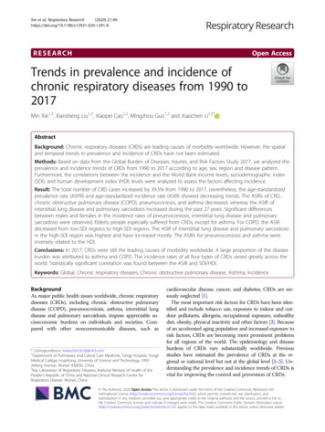
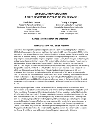
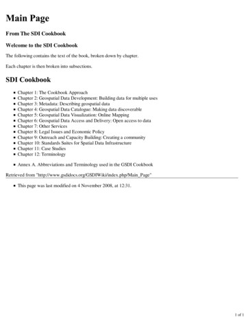
XTAL-CP CAPXTAL BUF OUTXTAL XTALOSCLF yDetectorDDI0DDI0ChargePumpEqualizer/Data MuxDDO1/RCOClock/DataBufferVCODDI1DDI1DE0 ENDE1 3DDI3SelectableDivideLOSDetectLDOControlSDO/EQ1 ENSCK/EQ2 ENCS/EQ3 ENHIFLOSSDI/EQ0 ENDDI A/CLOCKAUTOBYPASSDDO1 DISABLEDATA MUTEVDD 1p8GS2985 Functional Block DiagramRevision HistoryVersionECRPCNDateChanges and/or Modifications1152592–September2009Updates to Section 4.15 Host Interface.0152329–July 2009Converted document to PreliminaryData Sheet.D152240–July 2009Added Figure 4-2: De-emphasisWaveform.C152042–June 2009Removed ‘Proprietary & Confidential”from document.B151967–May 2009Added Section 4.15 Host Interface.A151318–April 2009New document.GS2985 Multi-Rate SDI Reclocker with Equalization &De-emphasisPreliminary Data Sheet36663 - 1September 20092 of 44
ion History .21. Pin Out.51.1 Pin Assignment .51.2 Pin Descriptions .62. Electrical Characteristics .92.1 Absolute Maximum Ratings .92.2 DC Electrical Characteristics .92.3 AC Electrical Characteristics . 103. Input/Output Circuits . 134. Functional Description . 184.1 Serial Data Input . 184.2 Modes of Operation . 184.3 Input Trace Equalization . 184.4 4:1 Input Mux . 194.5 Crystal Buffer . 204.6 LOS (Loss Of Signal) Detection . 204.7 Serial Digital Reclocker . 214.8 Lock Detection . 214.8.1 Lock Detect and Asynchronous Lock . 214.9 Serial Data Output . 224.9.1 Output Signal Interface Levels. 224.9.2 Adjustable Output Swing. 224.9.3 Output De-emphasis . 224.10 Automatic and Manual Data Rate Selection . 234.11 SD/HD Indication . 244.12 Bypass Mode . 244.13 DVB-ASI . 254.14 Output Mute and Data/Clock Output Selection . 254.15 Host Interface . 264.15.1 Introduction . 264.15.2 Legacy Mode & Startup . 264.15.3 Host Interface Mode & Startup . 264.15.4 Clock & Data Timing. 274.15.5 Single Device Operation. 274.15.6 Write Operation - Single Device . 284.15.7 Read Operation - Single Device . 284.15.8 Daisy Chain Operation. 314.15.9 Read & Write Operation - Daisy Chained Devices . 324.15.10 Writing to all Devices . 32GS2985 Multi-Rate SDI Reclocker with Equalization &De-emphasisPreliminary Data Sheet36663 - 1September 20093 of 44
4.15.11 Writing to a Single Device in the Chain . 334.15.12 Reading from all Devices . 334.15.13 Reading from a Single Device in the Chain. 344.15.14 Host Register Map. 354.16 Device Power Up . 394.17 Standby . 395. Typical Application Circuit . 406. Package and Ordering Information. 416.1 Package Dimensions . 416.2 Recommended PCB Footprint . 426.3 Packaging Data . 426.4 Marking Diagram . 436.5 Solder Reflow Profile . 436.6 Ordering Information . 44GS2985 Multi-Rate SDI Reclocker with Equalization &De-emphasisPreliminary Data Sheet36663 - 1September 20094 of 44
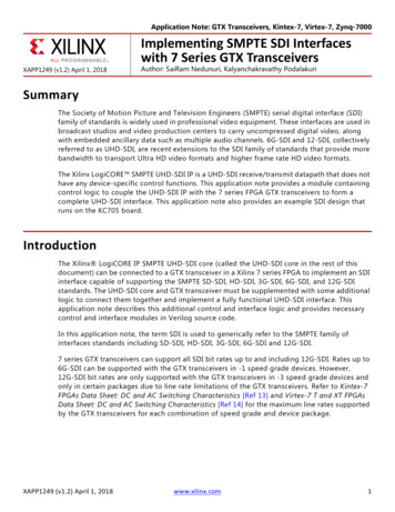
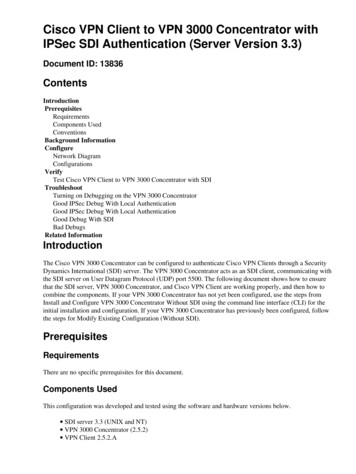
1. Pin Out535251GND54N/C55XTAL BUF OUT56XTAL 57CS/EQ3 ENSDI/EQ0 EN58N/C59XTAL-60SCK/EQ2 EN61SDO/EQ1 EN62N/C63VEE CPLF 64VCC CPN/CCP CAP1.1 Pin Assignment5049DDI0148VEE DDO0HIF247VCC DDO0DDI0346DDO0DE0 ENGND445DDI1544DDO0N/C643GND DRVDDI17GND8GS298564-pin QFN(top view)42VEE DDO141VCC DDO1DDI2940DDO1/RCON/C1039DE1 03132GND22VSS DIG21LOS20VDD DIG19LOCKEDGround Pad(bottom of package)18VDD 1P8SD/HD17SS133SS016N/CKBBGNDVEE VCO34VCC VCO15AUTO/MANDDO1 DISABLEDDI3BYPASSDATA MUTE35AUTOBYPASS3614DDI SEL113DDI SEL0DDI3RSVDFigure 1-1: GS2985 Pin OutGS2985 Multi-Rate SDI Reclocker with Equalization &De-emphasisPreliminary Data Sheet36663 - 1September 20095 of 44
1.2 Pin DescriptionsTable 1-1: GS2985 Pin DescriptionsPin NumberNameTypeDescription1, 3DDI0, DDI0Input2HIFLogic Input4, 8, 12, 16, 32,49GNDPowerConnect to GND.5, 7DDI1, DDI1InputSerial Digital Differential Input 1.6, 10, 24, 50, 54,59, 64N/CNo Connect9, 11DDI2, DDI2InputSerial Digital Differential Input 2.13, 15DDI3, DDI3InputSerial Digital Differential Input 3.14RSVDReserved17, 18DDI SEL[0:1]Logic InputSelects one of four serial digital input signals for processing. SeeSection 4.4.19BYPASSLogic InputBypasses the reclocker stage. See Section 4.12.20AUTOBYPASSLogic InputWhen HIGH, this pin automatically bypasses the reclocker stage when thePLL is not locked to a supported rate. See Section 4.12.21AUTO/MANLogic InputWhen set HIGH, the standard is automatically detected from the inputdata rate.22VCC VCOPowerMost positive power supply connection for the internalVCO section. Connect to a 3.3V supply with a 422Ω resistor, or to a 2.5Vsupply with a 267Ω resistor.23VEE VCOPowerMost negative power supply connection for the internalVCO section. Connect to GND.25, 26SS0, SS1Bi-directionalSerial Digital Differential Input 0.Host interface selection pin. Active-low input. See Section 4.15.14.Do not connect.Reserved pin. Do not connect to this pin.When HIGH, SS[1:0] are outputs displaying the data rate to which the PLLhas locked.When AUTO/MAN is HIGH and these pins are LOW, SS[1:0] are inputsforcing the PLL to lock only to the selected data rate.See Section 4.10.27VDD 1P8PowerExternal capacitor for internal 1.8V digital supply.28LOCKEDOutputLock Detect status signal. HIGH when the PLL is locked.29LOSOutputLoss Of Signal status. HIGH when the input signal is invalid.30VDD DIGPowerMost positive power supply connection for the digital core.Connect to 3.3V or 2.5V.31VSS DIGPowerMost negative power supply for the digital core.Connect to GND.GS2985 Multi-Rate SDI Reclocker with Equalization &De-emphasisPreliminary Data Sheet36663 - 1September 20096 of 44
Table 1-1: GS2985 Pin DescriptionsPin NumberNameTypeDescription33SD/HDOutput34KBBAnalog Input35DDO1 DISABLELogic InputDisables the DDO1/RCO and DDO1/RCO outputswhen LOW.See Section 4.14.36DATA MUTELogic InputMutes the DDO0/DDO0 and DDO1/DDO1 (if data is selected) outputs whenLOW.Set HIGH for normal operation.37DATA/CLOCKLogic InputDATA/CLOCK select.See Section 4.14.38, 40DDO1/RCO,DDO1/RCOOutput39DE1 ENLogic InputThis signal will be LOW for all rates other than 270Mb/s.This signal is HIGH for 270Mb/s.Controls the loop bandwidth of the PLL. Leave this pinfloating for serial reclocking applications.Differential serial clock or data outputs.De-emphasis on/off pin for serial digital output 1.HIGH de-emphasis onLOW de-emphasis off41VCC DDO1PowerMost positive power supply connection for the DDO1/DDO1 output driver.Connect to 3.3V or 2.5V.42VEE DDO1PowerMost negative power supply connection for the DDO1/DDO1 outputdriver. Connect to GND.43GND DRVPowerConnect to GND.44, 46DDO0, DDO0OutputDifferential Serial Digital Outputs.45DE0 ENLogic InputDe-emphasis on/off pin for serial digital output 0.HIGH de-emphasis onLOW de-emphasis off47VCC DDO0PowerMost positive power supply connection for the DDO0/DDO0 output driver.Connect to 3.3V or 2.5V.48VEE DDO0PowerMost negative power supply connection for the DDO0/DDO0 outputdriver.Connect to GND.51XTAL BUF OUTOutputBuffered output of the reference oscillator.52XTAL OutputReference crystal output.53XTAL-Input55CS/EQ3 ENInput/LogicInputReference crystal input.In host mode (HIF set LOW):Chip select input for SPI serial host interface. Active-low input.In non-host mode (HIF set HIGH):Trace equalization on/off pin for Serial Digital Differential Input 3.Active-high input.GS2985 Multi-Rate SDI Reclocker with Equalization &De-emphasisPreliminary Data Sheet36663 - 1September 20097 of 44
Table 1-1: GS2985 Pin DescriptionsPin NumberNameType56SCK/EQ2 ENInput/LogicInputDescriptionIn host mode (HIF set LOW):Burst-mode clock input for SPI serial host interface.In non-host mode (HIF set HIGH):Trace equalization on/off pin for Serial Digital Differential Input 2.Active-high input.57SDO/EQ1 ENInput/LogicInputIn host mode (HIF set LOW):Serial digital data output for SPI serial host interface. Active-high output.In non-host mode (HIF set HIGH):Trace equalization on/off pin for Serial Digital Differential Input 1.Active-high input.58SDI/EQ0 ENInput/LogicInputIn host mode (HIF set LOW):Serial digital data input for SPI serial host interface. Active-high input.In non-host mode (HIF set HIGH):Trace equalization on/off pin for Serial Digital Differential Input 0.Active-high input.60VEE CPPowerMost negative power supply connection for the internalcharge pump. Connect to GND.61VCC CPPowerMost positive power supply connection for the internal charge pump.Connect to 3.3V or 2.5V62LF PassiveLoop Filter capacitor connection. (CLF TBD nF). Connect as shown inTypical Application Circuit on page 40.63CP CAPPowerExternal capacitor for internal LDO regulator supplying the charge pumpcircuit. Center Pad GS2985 Multi-Rate SDI Reclocker with Equalization &De-emphasisPreliminary Data Sheet36663 - 1September 2009Ground pad on bottom of package. Connect to GND.8 of 44
2. Electrical Characteristics2.1 Absolute Maximum RatingsParameterValueSupply Voltage-0.5 to 3.6VDCInput ESD Voltage4kVStorage Temperature Range-50ºC TA 125ºCOperating Temperature Range-40ºC to 85ºCInput Voltage Range-0.3 to (VCC 0.3) VDCSolder Reflow Temperature260ºC2.2 DC Electrical CharacteristicsTable 2-1: DC Electrical 3.465V2.5V2.3752.52.625VVDD 3.3V 250325mWVDD 2.5V 180230mWPower (DDO1/RCO enabled, minimumoutput swing)VDD 3.3V 300390mWVDD 2.5V 210270mWPower in Power-down modeVDD 3.3V 4050mWVDD 2.5V 3040mWSupply VoltagePower (DDO1/RCO disabled, minimumoutput swing)SymbolVDDPConditionsSerial Input Termination Differential80100120ΩSerial Output Termination Differential80100120ΩSerial Input Common Mode Voltage 1.6 VDDVSerial Output Common Mode Voltage VCC(ΔVOD/2) VVIL (2.5V operation) VOUT VOL, max-0.3 0.7VVOUT VOL, max-0.3 0.8VVIL (3.3V operation)GS2985 Multi-Rate SDI Reclocker with Equalization &De-emphasisPreliminary Data Sheet36663 - 1September 20099 of 44
Table 2-1: DC Electrical Characteristics (Continued)ParameterSymbolConditions VIH (2.5V operation)VIH (3.3V operation)MinTypMaxUnitsVOUT VOH, min1.7 VDD 0.3VVOUT VOH, min2 VDD 0.3VIIN VIN 0V or VIN VDD /-10μAVOL (2.5V operation) VDD min, IOL 100μA 0.4VVDD min, IOL 100μA 0.4VVDD min, IOH -100μA2.1 VVDD min, IOH -100μAVDD-0.4 V2.5V operation 350 mV3.3V operation 420 mVVOL (3.3V operation) VOH (2.5V operation)VOH (3.3V operation) Hysteresis Voltage (SPI inputs)2.3 AC Electrical CharacteristicsTable 2-2: AC Electrical CharacteristicsParameterSerial Input Data Rate(for reclocking)SymbolDRSDOSerial Input Data Rate(bypass)ConditionsMinTypMaxUnitsNotes 0.27 2.97Gb/s DC 2.97Gb/s 10MHz 2000mVp-pd SPI Operating Speed Input Voltage SwingΔVSDIset ATTEN EN 1 forΔVSDI 1Vpp100Output Voltage SwingΔVODdefault300400500mVp-pd see DRIVER 1 register(0x01) addresses 8 & 9 in4.15.14 Host RegisterMap.6008001000mVp-pd LOWRecommended setting for 0 to 10inches of FR4 MEDRecommended setting for 10 to 20inches of FR4 HIGHRecommended setting for 20 inchesof FR4 Input Trace Equalization GS2985 Multi-Rate SDI Reclocker with Equalization &De-emphasisPreliminary Data Sheet36663 - 1September 200910 of 44
Table 2-2: AC Electrical Characteristics (Continued)ParameterOutput De-EmphasisSymbol Input Jitter ToleranceLoop BandwidthConditionsMinTypMaxUnitsNotesOFF - 0 0 dB ON - 0 0 dB ON - 1 0.7 dB ON - 2 1.3 dB ON - 3 2 dB ON - 4 2.6 dB ON - 5 3.3 dB ON - 6 4 dB ON - 7 4.7 dB 0.8 UI KBB VCC 170 kHz KBB FLOAT 340 kHz KBB GND 680 kHz KBB VCC 0.875 MHz KBB FLOAT 1.75 MHz KBB GND 3.5 MHz KBB VCC 1.75 MHz KBB FLOAT 3.5 MHz KBB GND 7.0 MHz square-wave OP(2970Mb/s)PLL Lock Time (asynchronous)talock 0.51ms PLL Lock Time (synchronous)tslockCLF 47nF, SD/HD 0 0.54μs CLF 47nF, SD/HD 1 510μs KBB FLOAT 0.010.02UI1 0.030.04UI1 0.050.08UI120% to 80% (400mVswing) 6590ps 20% to 80% (800mVswing) 80110ps 15ps Serial Data Output Jitter Intrinsic(DDO0)tOJ(270Mb/s)PRN 2 23-1 test patterntOJ(1485Mb/s)KBB FLOATPRN 2 23-1 test patterntOJ(2970Mb/s)KBB FLOATPRN 2 23-1 test patternOutput Rise/Fall TimeOutput Rise/Fall Time Mismatchtr/f GS2985 Multi-Rate SDI Reclocker with Equalization &De-emphasisPreliminary Data Sheet36663 - 1September 200911 of 44
Table 2-2: AC Electrical Characteristics NotesEye Cross Shift percentage of signalamplitude 5% Power Supply Noise Rejection 50 - 100Hz 100 mVp-p 100Hz - 10MHz 40 mVp-p 10MHz - 1.485GHz 10 mVp-p Notes:1. Accumulated jitter measured peak to peak differential over 1000 hits.GS2985 Multi-Rate SDI Reclocker with Equalization &De-emphasisPreliminary Data Sheet36663 - 1September 200912 of 44
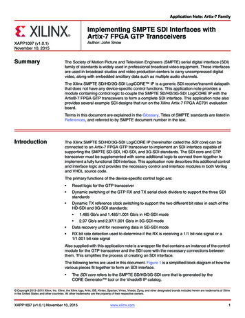
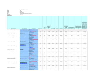
3. Input/Output �DDIFigure 3-1: High-speed Inputs (DDI0, DDI0, DDI1, DDI1, DDI2, DDI2, DDI3, DDI3)VCC2.5µAVCC1.4kΩINVREFFigure 3-2: Low-speed Input with weak internal pull-up (HIF, RSVD, AUTO/MAN,DDO1 DISABLE, DATA MUTE)GS2985 Multi-Rate SDI Reclocker with Equalization &De-emphasisPreliminary Data Sheet36663 - 1September 200913 of 44
VCCVCC1.4kΩINVREF2.5µAFigure 3-3: Low-speed Input with weak internal pull-down (DDI SEL0,DDI SEL1, BYPASS, AUTOBYPASS, DE1 EN, DE0 anFigure 3-4: Data Rate Control/Indicators (SS0, SS1)GS2985 Multi-Rate SDI Reclocker with Equalization &De-emphasisPreliminary Data Sheet36663 - 1September 200914 of 44
VCCVCC972ΩOUTFigure 3-5: Low-speed Outputs (LOCKED, LOS, HD/SD)VCCVCCVCC50Ω50ΩDDODDOFigure 3-6: High-speed Outputs (DDO1/RCO, DDO1/RCO, DDO0, DDO0)VCCVREF 1VCCVCC1.4kΩKBBVCCVREF 2Figure 3-7: Loop Bandwidth Control (KBB)GS2985 Multi-Rate SDI Reclocker with Equalization &De-emphasisPreliminary Data Sheet36663 - 1September 200915 of 44
VCCVCCXTAL BUFF OUTFigure 3-8: Crystal Buffered Output (XTAL BUF OUT)VCCVCCENVCCVCCXTAL 246ΩXTALENFigure 3-9: High-speed Crystal Oscillator I/O (XTAL-, XTAL )VCCINVCC1kΩ2.5µAFigure 3-10: SPI Inputs/EQ Ctrl (CS/EQ3 EN, SCK/EQ2 EN, SDI/EQ0 EN)GS2985 Multi-Rate SDI Reclocker with Equalization &De-emphasisPreliminary Data Sheet36663 - 1September 200916 of 44
VCCVCC1.4kΩVREF2.5µAVCCTgateSDOSPI SDOtri-stateLogicFigure 3-11: SPI Output/EQ Control (SDO/EQ1 EN)GS2985 Multi-Rate SDI Reclocker with Equalization &De-emphasisPreliminary Data Sheet36663 - 1September 200917 of 44
4. Functional DescriptionThe GS2985 is a multi-standard reclocker for serial digital SDTV signals operating at 270Mb/s,and HDTV signals operating at 1.485Gb/s, 1.485/1.001Gb/s, 2.97Gb/s and 2.97/1.001Gb/s.4.1 Serial Data InputThe GS2985 features four differential input buffers.The serial data input signal is connected to the DDI0/DDI0, DDI1/DDI1, DDI2/DDI2 andDDI3/DDI3 input pins of the device.Input signals can be single-ended or differential, DC or AC-coupled.The input circuit is self-biasing, to allow for simple AC or DC-coupling of input signals to thedevice.The serial digital data inputs are also compatible when DC-coupled with LVPECL or CMLdifferential outputs from crosspoint switches which operate from 3.3V or 2.5V supplies. Thisincludes but is not limited to: GS2974A, GS2974B, and GS2984 equalizers.4.2 Modes of OperationThe GS2985 has two modes of operation: Legacy Mode (HIF HIGH) and SPI Mode (HIF LOW).In Legacy Mode, chip functions are controlled via pins only, and offers limited control of inputequalization and output de-emphasis.In SPI mode, access is gained to additional EQ and DE settings as well as access to additionalfeatures such as LOS adjustment, polarity invert, auto-mute, etc.4.3 Input Trace EqualizationThe GS2985 features adjustable trace equalization to compensate for PCB trace dielectric lossesat 1.5GHz.The trace equalization has three peak-gain settings. The maximum peak gain value is optimizedfor compensating the high-frequency losses associated with 25 inches of 5-mil stripline in FR4material. For boards with different striplines or materials, users can experiment to find the EQsetting which optimizes their system performance.These settings are accessible via the serial host interface.Each serial digital input; DDI, DDI includes a pin EQn EN to turn its trace equalizer on or off.When a pin EQn EN is tied LOW or left unconnected, the trace equalization for input n is set tothe Low Range.When an EQn EN pin is tied HIGH, and input n is selected, the trace equalization for input n isset to the Medium Range.GS2985 Multi-Rate SDI Reclocker with Equalization &De-emphasisPreliminary Data Sheet36663 - 1September 200918 of 44
Table 4-1: Input Trace Equalization OperationEQn EN SettingTrace Equalization RangeLOWLowHIGHMediumThe default peak-gain setting upon power-up is optimized for compensating thehigh-frequency losses associated with approximately 10 inches of 5-mil stripline in FR4material.The EQn EN pins are multiplexed with the serial host interface pins. The EQn EN functionalityis enabled when pin HIF is tied HIGH, as shown in Table 4-2:Table 4-2: EQn EN Pins MultiplexedPinFunctionSDI/EQ0 ENActive-high logic input to enable trace-equalization for high-speed input channel 0.SDO/EQ1 ENActive-high logic input to enable trace-equalization for high-speed input channel 1.SCK/EQ2 ENActive-high logic input to enable trace-equalization for high-speed input channel 2.CS/EQ3 ENActive-high logic input to enable trace-equalization for high-speed input channel 3.4.4 4:1 Input MuxThe GS2985 incorporates a 4:1 input mux, which allows the connection of four independentstreams of video/data. There are four differential inputs (DDI[3:0] / DDI[3:0]). The active channelcan be selected via the DDI SEL[1:0] pins as shown in Table 4-3.Table 4-3: Input Selection TableDDI SEL[1:0]Selected Input00DDI001DDI110DDI211DDI3The DDI SEL pins include internal pull-downs, which pull the input voltage LOW if either pinis unconnected. Active circuitry associated with the input buffers and trace EQ can only beturned on for the selected input. Inputs which are not selected have their input buffers and traceEQs turned OFF to save power. Unused inputs can be either left floating, or tied to VCC.GS2985 Multi-Rate SDI Reclocker with Equalization &De-emphasisPreliminary Data Sheet36663 - 1September 200919 of 44
4.5 Crystal BufferThe GS2985 features a crystal buffer supporting a Gennum recommended external 27MHzcrystal. The GS2985 requires an external 27MHz reference clock for correct operation. Thisreference clock is generated by connecting a crystal to the XTAL- and XTAL pins of the device.Alternately, a 27MHz external clock source can be connected to the XTAL- pin of the device,while the XTAL pin should be left floating.4.6 LOS (Loss Of Signal) DetectionThe LOS (Loss Of Signal) status pin is an active-high output that indicates when the serial digitalinput signal selected at the 4:1 input mux is invalid. In order for this output to be asserted,transitions must not be present for a period of tLA 5 - 10μs. After this output has been asserted,LOS will de-assert within tLD 0 - 5μs after the appearance of a transition at the DDIx input. SeeFigure 4-1.This signal is HIGH (signal lost), when the number of data edges within a window is below adefined threshold. The output is automatically muted when LOS is detected.This signal is LOW (signal valid), when the number of data edges within a window is above adefined threshold. See Table 4-4.Table 4-4: LOS OperationLOSSignalHIGHInvalidLOWValidThe LOS function is operational for all operating modes of the device.t LAt LDDATALOSFigure 4-1: LOS Signal TimingThe LOS detector has two major modes. In legacy mode, a simple edge-based detector is used tomonitor the received signal at the output of the data slicer. Since the incoming signal hasundergone considerable gain by this point, the legacy detector can be more susceptible to falsede-assertion of LOS for unused channels which experience significant cross-talk from adjacentactive channels.GS2985 Multi-Rate SDI Reclocker with Equalization &De-emphasisPreliminary Data Sheet36663 - 1September 200920 of 44
The new LOS detector uses a measure of both signal amplitude and duration to minimize falsedetection of the impulse like signals that are characteristic of cross-talk. In this mode, the signalis tapped off at the output of the equalizer stage, prior to the high gain buffers.The threshold setting within the detector can be adjusted to increase or decrease its sensitivity.Gennum recommends using the least sensitive thre
GS2985 Multi-Rate SDI Reclocker with Equalization & De-emphasis GS2985 Multi-Rate SDI Reclocker with Equalization & 1 of 44 De-emphasis Preliminary Data Sheet 36663 - 1 September 2009 www.gennum.com Features SMPTE 424M, SMPTE 292M and SMPTE 259M-C compliant Supports DVB-ASI at 270Mb/s Single supply operation at 3.3V or 2.5V