Transcription
Congestion Control for Large-Scale RDMADeploymentsYibo Zhu1,3 Haggai Eran2 Daniel Firestone1 Chuanxiong Guo1 Marina Lipshteyn1Yehonatan Liron2 Jitendra Padhye1 Shachar Raindel2 Mohamad Haj Yahia2 Ming Zhang11Microsoft2MellanoxABSTRACTModern datacenter applications demand high throughput(40Gbps) and ultra-low latency ( 10 µs per hop) from thenetwork, with low CPU overhead. Standard TCP/IP stackscannot meet these requirements, but Remote Direct Memory Access (RDMA) can. On IP-routed datacenter networks,RDMA is deployed using RoCEv2 protocol, which relies onPriority-based Flow Control (PFC) to enable a drop-free network. However, PFC can lead to poor application performance due to problems like head-of-line blocking and unfairness. To alleviates these problems, we introduce DCQCN, an end-to-end congestion control scheme for RoCEv2.To optimize DCQCN performance, we build a fluid model,and provide guidelines for tuning switch buffer thresholds,and other protocol parameters. Using a 3-tier Clos networktestbed, we show that DCQCN dramatically improves throughput and fairness of RoCEv2 RDMA traffic. DCQCN is implemented in Mellanox NICs, and is being deployed in Microsoft’s datacenters.CCS Concepts Networks Transport protocols;KeywordsDatacenter transport; RDMA; PFC; ECN; congestion control1.INTRODUCTIONDatacenter applications like cloud storage [16] need highbandwidth (40Gbps or more) to meet rising customer demand. Traditional TCP/IP stacks cannot be used at suchspeeds, since they have very high CPU overhead [29]. ThePermission to make digital or hard copies of all or part of this work for personalor classroom use is granted without fee provided that copies are not made ordistributed for profit or commercial advantage and that copies bear this noticeand the full citation on the first page. Copyrights for components of this workowned by others than ACM must be honored. Abstracting with credit is permitted. To copy otherwise, or republish, to post on servers or to redistribute tolists, requires prior specific permission and/or a fee. Request permissions frompermissions@acm.org.SIGCOMM ’15, August 17–21, 2015, London, United Kingdomc 2015 ACM. ISBN 978-1-4503-3542-3/15/08. . . 15.00DOI: http://dx.doi.org/10.1145/2785956.27874845233U. C. Santa Barbarabrutal economics of cloud services business dictates that CPUusage that cannot be monetized should be minimized: a corespent on supporting high TCP throughput is a core that cannot be sold as a VM. Other applications such as distributedmemory caches [10, 30] and large-scale machine learningdemand ultra-low latency (less than 10 µs per hop) message transfers. Traditional TCP/IP stacks have far higherlatency [10].We are deploying Remote Direct Memory Access (RDMA)technology in Microsoft’s datacenters to provide ultra-lowlatency and high throughput to applications, with very lowCPU overhead. With RDMA, network interface cards (NICs)transfer data in and out of pre-registered memory buffers atboth end hosts. The networking protocol is implemented entirely on the NICs, bypassing the host networking stack. Thebypass significantly reduces CPU overhead and overall latency. To simplify design and implementation, the protocolassumes a lossless networking fabric.While the HPC community has long used RDMA in specialpurpose clusters [11, 24, 26, 32, 38], deploying RDMA on alarge scale in modern, IP-routed datacenter networks presentsa number of challenges. One key challenge is the need fora congestion control protocol that can operate efficiently ina high-speed, lossless environment, and that can be implemented on the NIC.We have developed a protocol, called Datacenter QCN(DCQCN) for this purpose. DCQCN builds upon the congestion control components defined in the RoCEv2 standard.DCQCN is implemented in Mellanox NICs, and is currentlybeing deployed in Microsoft’s datacenters.To understand the need for DCQCN, it is useful to pointout that historically, RDMA was deployed using InfiniBand(IB) [19, 21] technology. IB uses a custom networking stack,and purpose-built hardware. The IB link layer (L2) uses hopby-hop, credit-based flow control to prevent packet dropsdue to buffer overflow. The lossless L2 allows the IB transport protocol (L4) to be simple and highly efficient. Much ofthe IB protocol stack is implemented on the NIC. IB supportsRDMA with so-called single-sided operations, in which aserver registers a memory buffer with its NIC, and clientsread (write) from (to) it, without further involvement of theserver’s CPU.However, the IB networking stack cannot be easily de-
2.ployed in modern datacenters. Modern datacenters are builtwith IP and Ethernet technologies, and the IB stack is incompatible with these. DC operators are reluctant to deploy andmanage two separate networks within the same datacenter.Thus, to enable RDMA over Ethernet and IP networks, theRDMA over Converged Ethernet (RoCE) [20] standard, andits successor RoCEv2 [22] have been defined. RoCEv2 retains the IB transport layer, but replaces IB networking layer(L3) with IP and UDP encapsulation, and replaces IB L2with Ethernet. The IP header is needed for routing, whilethe UDP header is needed for ECMP [15].To enable efficient operation, like IB, RoCEv2 must alsobe deployed over a lossless L2. To this end, RoCE is deployed using Priority-based Flow Control (PFC) [18]. PFCallows an Ethernet switch to avoid buffer overflow by forcing the immediate upstream entity (either another switch ora host NIC) to pause data transmission. However, PFC isa coarse-grained mechanism. It operates at port (or, portplus priority) level, and does not distinguish between flows.This can cause congestion-spreading, leading to poor performance [1, 37].The fundamental solution to PFC’s limitations is a flowlevel congestion control protocol. In our environment, theprotocol must meet the following requirements: (i) function over lossless, L3 routed, datacenter networks, (ii) incurlow CPU overhead on end hosts, and (iii) provide hyper-faststart in the common case of no congestion. Current proposals for congestion control in DC networks do not meet all ourrequirements. For example, QCN [17] does not support L3networks. DCTCP [2] and iWarp [35] include a slow startphase, which can result in poor performance for bursty storage workloads. DCTCP and TCP-Bolt [37] are implementedin software, and can have high CPU overhead.Since none of the current proposals meet all our requirements, we have designed DCQCN. DCQCN is an end-toend congestion control protocol for RoCEv2, to enable deployment of RDMA in large, IP-routed datacenter networks.DCQCN requires only the standard RED [13] and ECN [34]support from the datacenter switches. The rest of the protocol functionality is implemented on the end host NICs. DCQCN provides fast convergence to fairness, achieves highlink utilization, ensures low queue buildup, and low queueoscillations.The paper is organized as follows. In §2 we present evidence to justify the need for DCQCN. The detailed designof DCQCN is presented in §3, along with a brief summaryof hardware implementation. In §4 we show how to set thePFC and ECN buffer thresholds to ensure correct operationof DCQCN. In §5 we describe a fluid model of DCQCN,and use it to tune protocol parameters. In §6, we evaluatethe performance of DCQCN using a 3-tier testbed and tracesfrom our datacenters. Our evaluation shows that DCQCNdramatically improves throughput and fairness of RoCEv2RDMA traffic. In some scenarios, it allows us to handle asmuch as 16x more user traffic. Finally, in §7, we discusspractical issues such as non-congestion packet losses.THE NEED FOR DCQCNTo justify the need for DCQCN, we will show that TCPstacks cannot provide high bandwidth with low CPU overhead and ultra-low latency, while RDMA over RoCEv2 can.Next, we will show that PFC can hurt performance of RoCEv2.Finally, we will argue that existing solutions to cure PFC’sills are not suitable for our needs.2.1Conventional TCP stacks perform poorlyWe now compare throughput, CPU overhead and latencyof RoCEv2 and conventional TCP stacks. These experiments use two machines (Intel Xeon E5-2660 2.2GHz, 16core, 128GB RAM, 40Gbps NICs, Windows Server 2012R2)connected via a 40Gbps switch.Throughput and CPU utilization: To measure TCP throughput, we use Iperf [46] customized for our environment. Specifically, we enable LSO [47], RSS [49], and zero-copy operations and use 16 threads. To measure RDMA throughput, weuse a custom tool that uses IB READ operation to transferdata. With RDMA, a single thread saturates the link.Figure 1(a) shows that TCP has high CPU overhead. Forexample, with 4MB message size, to drive full throughput,TCP consumes, on average, over 20% CPU cycles acrossall cores. At smaller message sizes, TCP cannot saturatethe link as CPU becomes the bottleneck. Marinos et.al. [29]have reported similarly poor TCP performance for Linux andFreeBSD. Even the user-level stack they propose consumesover 20% CPU cycles. In contrast, the CPU utilization ofthe RDMA client is under 3%, even for small message sizes.The RDMA server, as expected, consumes almost no CPUcycles.Latency: Latency is the key metric for small transfers. Wenow compare the average user-level latency of transferringa 2K message, using TCP and RDMA. To minimize TCPlatency, the connections were pre-established and warmed,and Nagle was disabled. Latency was measured using a highresolution ( 1 µs) timer [48]. There was no other traffic onthe network.Figure 1(c) shows that TCP latency (25.4 µs) is significantly higher than RDMA (1.7 µs for Read/Write and 2.8µs for Send). Similar TCP latency has reported in [10] forWindows, and in [27] for Linux.2.2PFC has limitationsRoCEv2 needs PFC to enable a drop-free Ethernet fabric. PFC prevents buffer overflow on Ethernet switches andNICs. The switches and NICs track ingress queues. Whenthe queue exceeds a certain threshold, a PAUSE messageis sent to the upstream entity. The uplink entity then stopssending on that link till it gets an RESUME message. PFCspecifies upto eight priority classes. PAUSE/RESUME messages specify the priority class they apply to.The problem is that the PAUSE mechanism operates ona per port (and priority) basis – not on a per-flow basis.This can lead to head-of-line blocking problems; resultingin poor performance for individual flows. We now illustrate524
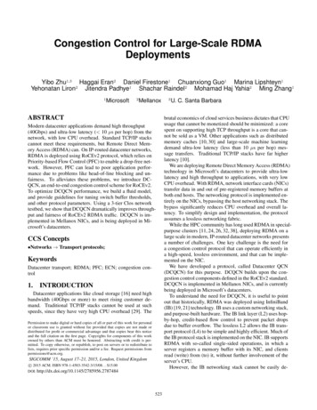
RDMATCP4KB16KB 64KB 256KB 1MBMessage size100Time to transfer 2KB (µs)CPU utilization (%)Throughput (Gbps)4035302520151050TCP serverRDMA serverRDMA client8060402004MB4KB 16KB 64KB 256KB 1MBMessage size(a) Mean Throughput4MB3020100TCP(b) Mean CPU UtilizationRDMA(read/write)RDMA(send)(c) Mean LatencyFigure 1: Throughput, CPU consumption and latency of TCP and 4T1T2T3T4H2H41Figure 2: Testbed topology. All linksare 40Gbps. All switches are Arista7050QX32. There are four ToRs (T1-T4),four leaves (L1-L4) and two spines (S1S2). Each ToR represents a different IPsubnet. Routing and ECMP is done viaBGP. Servers have multiple cores, largeRAMs, and 40Gbps NICs.H3P4T4P2P1H4RH11H1420151050H1H2H3H4Host(b) Throughput of individual sendersFigure 3: PFC Unfairnessthe problems using a 3-tier testbed (Figure 2) representativeof modern datacenter networks.Unfairness: Consider Figure 3(a). Four senders (H1-H4)send data to the single receiver (R) using RDMA WRITEoperation. All senders use the same priority class. Ideally,the four senders should equally share bottleneck link (T4 toR). However, with PFC, there is unfairness. When queuestarts building up on T4, it pauses incoming links (ports P2P4). However, P2 carries just one flow (from H4), whileP3 and P4 may carry multiple flows since H1, H2 and H3must share these two ports, depending on how ECMP mapsthe flows. Thus, H4 receives higher throughput than H1-H3.This is known as the parking lot problem [14].This is shown in Figure 3(b), which shows the min, median and max throughput achieved by H1-H4, measured over1000 4MB data transfers. H4 gets as much as 20Gbps throughput, e.g. when ECMP maps all of H1-H3 to either P3 orP4. H4’s minimum throughput is higher than the maximumthroughput of H1-H3.Victim flow: Because PAUSE frames can have a cascadingeffect, a flow can be hurt by congestion that is not even onits path. Consider Figure 4(a). Four senders (H11-H14),send data to R. In addition, we have a “victim flow” – VS525VSVRH31H32R(a) Topology(a) TopologyThroughput (Gbps)H21Throughput (Gbps)H11L1L4P3T1S22520151050012Number of senders under T3(b) Median throughput of victim flowFigure 4: Victim flow problemsending to VR. Figure 4(b) shows the median throughput(250 transfers of 250MB each) of the victim flow.When there are no senders under T3, in the median case(two of H11-H14 map to T1-L1, others to T1-L2. Each ofH11-H14 gets 10Gbps throughput. VS maps to one of T1’suplinks), one might expect VS to get 20Gbps throughput.However, we see that it only gets 10Gbps. This is due tocascading PAUSEs. As T4 is the bottleneck of H11-H14incast, it ends up PAUSEing its incoming links. This in turnleads to L3 and L4 to pause their incoming links, and soforth. Eventually, L1 and L2 end up pausing T1’s uplinksto them, and T1 is forced to PAUSE the senders. The flowson T1 that use these uplinks are equally affected by thesePAUSEs, regardless of their destinations – this is also knownas the head-of-the-line blocking problem.The problem gets worse as we start senders H31 and H32that also send to R. We see that the median throughput further falls from 10Gbps to 4.5Gbps, even though no path fromH31 and H32 to R has any links in common with the pathbetween VS and VR. This happens because H31 and H32compete with H11-H14 on L3 and L4, make them PAUSES1 and S2 longer, and eventually make T1 PAUSE senderslonger.
3.Summary: These experiments show that flows in RoCEv2deployments may see lower throughput and/or high variability due to PFC’s congestion-spreading characteristics.2.3THE DCQCN ALGORITHMDCQCN is a rate-based, end-to-end congestion protocol,that builds upon QCN [17] and DCTCP [2]. Most of theDCQCN functionality is implemented in the NICs.As mentioned earlier, we had three core requirements forDCQCN: (i) ability to function over lossless, L3 routed, datacenter networks, (ii) low CPU overhead and (iii) hyperfast start in the common case of no congestion. In addition, we also want DCQCN to provide fast convergence tofair bandwidth allocation, avoid oscillations around the stable point, maintain low queue length, and ensure high linkutilization.There were also some practical concerns: we could notdemand any custom functionality from the switches, andsince the protocol is implemented in NIC, we had to be mindful of implementation overhead and complexity.The DCQCN algorithm consists of the sender (reactionpoint (RP)), the switch (congestion point (CP)), and the receiver, (notification point (NP)).Existing proposals are inadequateA number of proposals have tried to address PFC’s limitations. Some have argued that ECMP can mitigate theproblem by spreading traffic on multiple links. Experimentsin previous section show that this is not always the case.The PFC standard itself includes a notion of priorities to address the head-of-the-line blocking problem. However, thestandard supports only 8 priority classes, and both scenariosshown above can be made arbitrarily worse by expanding thetopology and adding more senders. Moreover, flows withinthe same class will still suffer from PFC’s limitations.The fundamental solution to the PFC’s problems is to useflow-level congestion control. If appropriate congestion control is applied on a per-flow basis, PFC will be rarely triggered, and thus the problems described earlier in this sectionwill be avoided.The Quantized Congestion Notification (QCN) [17] standard was defined for this purpose. QCN enables flow-levelcongestion control within an L2 domain. Flows are definedusing source/destination MAC address and a flow id field.A switch computes a congestion metric upon each packetarrival. Its value depends on the difference between the instantaneous queue size and the desired equilibrium queuesize, along with other factors. The switch then probabilistically (probability depends on the severity of the congestion)sends the quantized value of the congestion metric as feedback to the source of the arriving packet. The source reducesits sending rate in response to congestion feedback. Sinceno feedback is sent if there is no congestion, the sender increases its sending rate using internal timers and counters.QCN cannot be used in IP-routed networks because thedefinition of a flow is based entirely on L2 addresses. In IProuted networks the original Ethernet header is not preservedas the packet travels through the network. Thus a congestedswitch cannot determine the target to send the congestionfeedback to.We considered extending the QCN protocol to IP-routednetworks. However, this is not trivial to implement. At minimum, extending QCN to IP-routed networks requires using the IP five-tuple as flow identifier, and adding IP andUDP headers to the congestion notification packet to enableit to reach the right destination. Implementing this requireshardware changes to both the NICs and the switches. Making changes to the switches is especially problematic, as theQCN functionality is deeply integrated into the ASICs. Itusually takes months, if not years for ASIC vendors to implement, validate and release a new switch ASIC. Thus, updating the chip design was not an option for us.In §8 we will discuss why other proposals such as TCPBolt [37] and iWarp [35] do not meet our needs. Since theexisting proposals are not adequate, for our purpose, we propose DCQCN.3.1AlgorithmCP Algorithm: The CP algorithm is same as DCTCP. Atan egress queue, an arriving packet is ECN [34]-marked ifthe queue length exceeds a threshold. This is accomplishedusing RED [13] functionality (Figure 5) supported on allmodern switches. To mimic DCTCP, we can set Kmin Kmax K, and Pmax 1. Later, we will see that this isnot the optimal setting.NP Algorithm: ECN-marked packets arriving at NP indicate congestion in the network. NP conveys this informationback to the sender. The RoCEv2 standard defines explicitCongestion Notification Packets (CNP) [19] for this purpose.The NP algorithm specifies how and when CNPs should begenerated.The algorithm follows the state machine in Figure 6 foreach flow. If a marked packet arrives for a flow, and noCNP has been sent for the flow in last N microseconds, aCNP is sent immediately. Then, the NIC generates at mostone CNP packet every N microseconds for the flow, if anypacket that arrives within that time window was marked. Weuse N 50µs in our deployment. Processing a markedpacket, and generating the CNP are expensive operations, sowe minimize the activity for each marked packet. We discuss the implications in §5.RP Algorithm: When an RP (i.e. the flow sender) gets aCNP, it reduces its current rate (RC ) and updates the valueof the rate reduction factor, α, like DCTCP, and rememberscurrent rate as target rate (RT ) for later recovery. The valuesare updated as follows:1RT RC α RC ,RC (1 α/2),(1 g)α g,(1)The NP generates no feedback if it does not get any markedpackets. Thus, if RP gets no feedback for K time units, it1526Initial value of α is 1.
1Received a CNPPmaxCutRate();Reset(Timer, ByteCounter, T,BC, AlphaTimer);MarkingProbability0EgressQueue SizeKmaxKminFigure 5: Switch packet marking algorithmWait For Rate Increase Event();TimerexpiresReset(Timer);T ;ByteCounterexpiresUpdateAlpha();Wait For Alpha Timer();AlphaTimerexpiresReset(ByteCounter);BC ;First time of a flow, receive apacket with CE bits setSend CNP to thisflow’s sourceFastRecovery();YesMax(T, BC) F?NoAny packets for this flowwith CE bits set in 50μs?NoHyperIncrease();YesMin(T, BC) F?NoAdditiveIncrease();YesFigure 7: Pseudocode of the RP algorithmFigure 6: NP state machineupdates α, as shown in Equation (2). Note that K must belarger than the CNP generation timer. Our implementationuses K 55µs. See §5 for further discussion.α (1 g)α,Figure 8 shows that DCQCN solves the unfairness problem depicted in Figure 3. All four flows get equal share ofthe bottleneck bandwidth, and there is little variance. Figure 9 shows that DCQCN solves the victim flow problemdepicted in Figure 4. With DCQCN, the throughput of VSVR flow does not change as we add senders under T3.(2)Furthermore, RP increases its sending rate using a timer anda byte counter, in a manner identical to QCN [17]. The bytecounter increases rate for every B bytes, while the timer increases rate every T time units. The timer ensures that theflow can recover quickly even when its rate has dropped toa low value. The two parameters can be tuned to achievethe desired aggressiveness. The rate increase has two mainphases: fast recovery, where the rate is rapidly increased towards fixed target rate for F 5 successive iterations:RC (RT RC )/2,3.3CNP generation: DCQCN is not particularly sensitive tocongestion on the reverse path, as the send rate does not depend on accurate RTT estimation like TIMELY [31]. Still,we send CNPs with high priority, to avoid missing the CNPdeadline, and to enable faster convergence. Note that noCNPs are generated in the common case of no congestion.(3)Rate based congestion control: DCQCN is a rate-basedcongestion control scheme. We adopted a rate-based approach because it was simple to implement than the windowbased approach, and allowed for finer-grained control.Fast recovery is followed by an additive increase, where thecurrent rate slowly approaches the target rate, and target rateis increased in fixed steps RAI :RT RC RT RAI ,(RT RC )/2,Parameters: DCQCN is based on DCTCP and QCN, butit differs from each in key respects. For example, unlikeQCN, there is no quantized feedback, and unlike DCTCPthere is no “per-ack” feedback. Thus, the parameter settingsrecommended for DCTCP and QCN cannot be blindly usedwith DCQCN. In §5, we use a fluid model of the DCQCN toestablish the optimal parameter settings.(4)There is also a hyper increase phase for fast ramp up. Figure 7 shows the state machine. See [17] for more details.Note that there is no slow start phase. When a flow starts,it sends at full line rate, if there are no other active flowsfrom the host.2 This design decision optimizes the commoncase where flows transfer a relatively small amount of data,and the network is not congested [25].3.2The need for PFC: DCQCN does not obviate the need forPFC. With DCQCN, flows start at line rate. Without PFC,this can lead to packet loss and poor performance (§6).BenefitsHardware implementation: The NP and RP state machines are implemented on the NIC. The RP state machinerequires keeping one timer and one counter for each flowthat is being rate limited, apart from a small amount of otherstate such as the current value of alpha. This state is maintained on the NIC die. The rate limiting is on a per-packetBy providing per-flow congestion control, DCQCN alleviates PFC’s limitations. To illustrate this, we repeat the experiments in §2.2, with DCQCN enabled (parameters set according to guidelines in §4 and §5.2DiscussionOtherwise, starting rate is defined by local QoS policies.527
151050H1H2H3H4Host25Throughput (Gbps)Throughput (Gbps)Throughput (Gbps)2020151050012Number of senders under T34035302520151050ImplementationFluid Model00.020.040.06Time (second)0.080.1Figure 8: Throughput of individualsenders with DCQCN. Compare to Fig- Figure 9: Median throughput of “vic- Figure 10: Fluid model closely matchestim” flow with DCQCN. Compare toure 3(b).implementation.Figure 4(b).granularity. The implementation of NP state machine inConnectX-3 Pro can generate CNPs at the rate of one per1-5 microseconds. At link rate of 40Gbps, the receiver canreceive about 166 full-sized (1500 byte MTU) packets every 50 microseconds. Thus, the NP can typically supportCNP generation at required rate for 10-20 congested flows.The current version(ConnectX-4) can generate CNPs at therequired rate for over 200 flows.4.BUFFER SETTINGSCorrect operation of DCQCN requires balancing two conflicting requirements: (i) PFC is not triggered too early –i.e. before giving ECN a chance to send congestion feedback, and (ii) PFC is not triggered too late – thereby causingpacket loss due to buffer overflow.We now calculate the values of three key switch parameters: tf light , tP F C and tECN , to ensure that these two requirements are met even in the worst case. Note that different switch vendors use different terms for these settings; weuse generic names. The discussion is relevant to any sharedbuffer switch, but the calculations are specific to switcheslike Arista 7050QX32, that use the Broadcom Trident II chipset.These switches have 32 full duplex 40Gbps ports, 12MB ofshared buffer and support 8 PFC priorities.Headroom buffer tf light : A PAUSE message sent to anupstream device takes some time to arrive and take effect. Toavoid packet drops, the PAUSE sender must reserve enoughbuffer to process any packets it may receive during this time.This includes packets that were in flight when the PAUSEwas sent, and the packets sent by the upstream device whileit is processing the PAUSE message. The worst-case calculations must consider several additional factors (e.g., a switchcannot abandon a packet transmission it has begun) [8]. Following guidelines in [8], and assuming a 1500 byte MTU,we get tf light 22.4KB per port, per priority.PFC Threshold tP F C : This is the maximum size an ingressqueue can grow to, before a PAUSE message is sent to theupstream device. Each PFC priority gets its own queue ateach ingress port. Thus, if the total switch buffer is B, andthere are n ports, it follows that tP F C (B 8ntf light )/(8n).For our switches, we get tP F C 24.47KB. The switchsends RESUME message when the queue falls below tP F Cby two MTU.528ECN Threshold tECN : Once an egress queue exceeds thisthreshold, the switch starts marking packets on that queue(Kmin in Figure 5). For DCQCN to be effective, this threshold must be such that PFC threshold is not reached beforethe switch has a chance to mark packets with ECN.Note however, that ECN marking is done on egress queuewhile PAUSE messages are sent based on ingress queue.Thus, tECN is an egress queue threshold, while tP F C is aningress queue threshold.The worst case scenario is that packets pending on allegress queues come from a single ingress queue. To guarantee that PFC is not triggered on this ingress queue before ECN is triggered on any of the egress queues, we need:tP F C n tECN Using the upper bound on the value oftP F C , we get tECN 0.85KB. This is less than one MTUand hence infeasible.However, not only we do not have to use the upper boundon tP F C , we do not even have to use a fixed value for tP F C .Since the switch buffer is shared among all ports, tP F C shoulddepend on how much of the shared buffer is free. Intuitively, if the buffer is largely empty, we can afford to waitlonger to trigger PAUSE. The Trident II chipset in our switchallows us to configure a parameter β such that: tP F C β(B 8ntf light s)/8, where s is the amount of bufferthat is currently occupied. A higher β triggers PFC lessoften, while a lower value triggers PFC more aggressively.Note that s is equal to the sum of packets pending on allegress queues. Thus, just before ECN is triggered on anyegress port, we have: s n tECN . Hence, to ensurethat ECN is always triggered before PFC, we set: tECN β(B 8ntf light )/(8n(β 1)). Obviously, larger β leavesmore room for tECN . In our testbed, we use β 8, whichleads to tECN 21.75KB.Discussion: The above analysis is conservative, and ensures that PFC is not triggered on our switches before ECNeven in the worst case and when all 8 PFC priorities areused. With fewer priorities, or with larger switch buffers,the threshold values will be different.The analysis does not imply that PFC will never be triggered. All we ensure is that at any switch, PFC is not triggered before ECN. It takes some time for the senders to receive the ECN feedback and reduce their sending rate. During this time, PFC may be triggered. As discussed before,we rely on PFC to allow senders to start at line rate.
VariableRcRtαqtDescriptionCurrent RateTarget RateSee Equation (1)Queue SizeTimep(t) (5)(6) 0dαg 01 (1 p(t τ ))τ RC (t τ ) α(t)(7)dtτ RT (t) RC (t)dRT 1 (1 p(t τ ))τ RC (t τ )dtτ(1 p(t τ ))F B p(t τ ) RAI RC (t τ )(1 p(t τ )) B 1DescriptionSee Figure 5See Equation (1)Number of flows at bottleneckBandwidth of bottleneck linkFast recovery steps (fixed at 5)Byte counter for rate increaseTimer for rate increaseRate increase step (fixed at 40Mbps)Control loop delayInterval of Equation (2) RAI RC (t τ )(1 p(t τ ))F T RC (t τ ) p(t τ )(1 p(t τ )) T RC (t τ ) 1(8) RC (t)α(t)dRC 1 (1 p(t τ ))τ RC (t τ )dt2τRT (t) RC (t) RC (t τ )p(t τ ) 2(1 p(t τ )) B 1RT (t) RC (t)RC (t τ )p(t τ ) 2(1 p(t τ )) T RC (t τ ) 1(9)ANALYSIS OF DCQCNWe use a fluid model of DCQCN to determine the rightparameter settings for good performance.5.11,q(t) KminKmin q(t) Kmaxq(t) Kmaxdq N RC (t) CdtTable 2: Fluid model parameters5.q(t) Kminp,Kmax Kmin max Table 1: Fluid model variablesParameterKmin , Kmax , PmaxgNCFBTRAIτ τ0 0,Fluid Model of DCQCNFluid modelWe omit the proof for brevity. We verified that for reasonable settings, p is less than 1%. According to equation (5),when RED-ECN is enabled, there exists a fixed queue lengthpoint close to Kmin since p is close to 0. The value of g playsan important role in determining the stability of the queue,as we shall later see.To analyze convergence properties of DCQCN protocol, itis necessary to extend the fluid model to flows with differentrates. Take t
end congestion control protocol for RoCEv2, to enable de-ployment of RDMA in large, IP-routed datacenter networks. DCQCN requires only the standard RED [13] and ECN [34] support from the datacenter switches. The rest of the proto-col functionality is implemented on the end host NICs. DC-QCN provides fast convergence to fairness, achieves high