Transcription
Debugging via USB User s GuideRelease 02.2022MANUAL
Debugging via USB User s GuideTRACE32 Online HelpTRACE32 DirectoryTRACE32 IndexTRACE32 Documents . Debug Back-Ends . Debugging via USB User s Guide .1Introduction .5System Requirements5Contacting Support6Installation of the USB Driver .7Install the USB Driver on Windows7Install the USB Driver on Linux7Start a TRACE32 Session for USB Debugging .8Overview of Configuration Scenarios8Start the TRACE32 Session via T32Start11Debug Environment for Setup 1 (Single Instance)11Debug Environment for Setup 2 (Integrated Server)12Debug Environment for Setup 3 (Dedicated Server)14Start the TRACE32 Session without T32Start16Debug Environment for Setup 1 (Single Instance)16Debug Environment for Setup 2 (Integrated Server)16Debug Environment for Setup 3 (Dedicated Server)16Troubleshooting .18Select a USB Device via the GUI .19Select a USB Device via the TRACE32 Commands .21USB Specific SYStem.CONFIG Commands .22SYStem.CONFIG.stateOpen configuration window for USB debugging22SYStem.CONFIG.USBUSB configuration24Reset configuration of interface type26Connected USB devices27List connected USB devices27Filter the USB device tree29SYStem.CONFIG.USB.SELect.ExpandAllExpand tree29SYStem.CONFIG.USB.SELect.CollapseAllCollapse G.USB.SETBusPort 1989-2022 LauterbachConfigure all parameters of USB device31Configure device by bus port31Debugging via USB User s Guide 2
DEVice 1989-2022 LauterbachApply default USB settings32Configure device by VID/PID32Debugging via USB User s Guide 3
Debugging via USB User s GuideVersion 09-Mar-2022 1989-2022 LauterbachDebugging via USB User s Guide 4
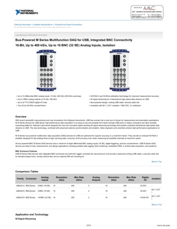
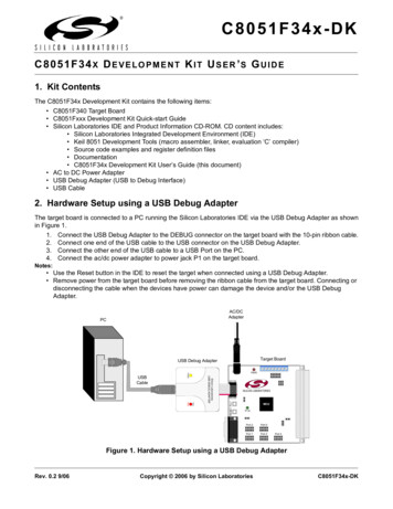
IntroductionSome debug target systems support debugging via the USB protocol. This can for example be debuggingvia TRACE32 with only a USB cable as the connection between PC and target (depending on the targetarchitecture, additional hardware or particular cables might be necessary).TRACE32LauterbachUSB driverHost computerUSBTarget underdebug(USB device)This document gives an introduction on how to configure and get started with a TRACE32 system fordebugging via the USB protocol.Therefore the following chapters provide a walkthrough on the installation of the necessary USB driversand on how to configure the TRACE32 system. In addition, they cover the USB commands inTRACE32.System RequirementsHardware requirements: USB Cable: The necessary cable type depends on the target system:-USB device targets: If the target acts as a USB device, then a standard USB 3.0 cable canbe used. Example for targets that are mostly USB devices: smarthphones.-USB host targets: If the target acts as a USB host, then a so-called “A-to-A” or “Male-toMale” USB 3.0 cable must be used. Such cables typically omit the “Vbus”, “D ” and “D-” wiresand are made of particularly high quality. Examples for targets that are mostly USB hosts:laptops and workstations.Software requirements: USB driver installation files: On Windows host PCs, a dedicated USB target driver isnecessary for USB debugging. For more information about the driver, see chapter “Installation ofthe USB Driver”. TRACE32 version: Whether the build number of your TRACE32 installation already supportsdebugging via the USB protocol does depend on the target system. For more details, pleasecontact Lauterbach support. 1989-2022 LauterbachDebugging via USB User s Guide 5
Contacting SupportLAUTERBACH GmbHAltlaufstrasse 4085635 Hoehenkirchen-SiegertsbrunnGermanyPhone( 49) 8102-9876-555Fax( 49) upport.html or https://www.lauterbach.com/report.htmlHere you’ll find local and special support addresses.E-mailsupport@lauterbach.comGeneral support address where your request will be answered within a short time if it isa basic support request or redirected to the appropriate address.Be sure to include detailed system information about your TRACE32 configuration.1.To generate a system information report, choose TRACE32 Help Support Systeminfo.NOTE:Please help to speed up processing of your support request. By filling out thesystem information form completely and with correct data, you minimize thenumber of additional questions and clarification request e-mails we need toresolve your problem.2.Preferred: click Save to File, and send the system information as an attachment to your e-mail.3.Click Save to Clipboard, and then paste the system information into your e-mail. 1989-2022 LauterbachDebugging via USB User s Guide 6
Installation of the USB DriverIn order to use TRACE32 for USB debugging, it is necessary that the required USB driver is installed on thehost PC. Depending on the operating system of the host PC, continue with “Install the USB Driver onWindows” or with “Install the USB Driver on Linux”.NOTE:The TRACE32 Target USB Driver is used to address a debug target.Do not confuse this driver with the Lauterbach USB driver that addressesLauterbach hardware such as the POWER DEBUG PRO.Install the USB Driver on WindowsTo install the TRACE32 Target USB Driver:1.Make sure that your target USB device is powered and connected to the host PC.2.Navigate to the TRACE32 system directory (by default c:\t32) and double-click /bin/windows/drivers/setup t32 target usb driver.exe3.In the TRACE32 Target USB Driver Installation window, follow the instructions of the installationwizard.Once the TRACE32 Target USB Driver has been installed on the host PC, continue with “Start a TRACE32Session for USB Debugging”, page 8.Install the USB Driver on LinuxOn a Linux host operating system, no USB driver installation is necessary. Continue with “Start a TRACE32Session for USB Debugging”, page 8. 1989-2022 LauterbachDebugging via USB User s Guide 7
Start a TRACE32 Session for USB DebuggingIn this section: Overview of Configuration Scenarios: Introduces the three different USB debugging scenarios. Start the TRACE32 Session via T32Start: Describes how to configure software-only debugenvironments in T32Start for use in TRACE32 PowerView. The T32Start application assists you inconfiguring the desired setup. This way you do not need to manually edit any config.t32 file. Start the TRACE32 Session without T32Start: Describes how to configure software-only debugenvironments by manually creating a configuration file for use in TRACE32 PowerView. Choose amanual configuration if you do not want to use T32Start, or if you work with Linux.NOTE:The T32Start application is currently only available for Windows. For moreinformation about T32Start, refer to “T32Start” (app t32start.pdf).Overview of Configuration ScenariosThe TRACE32 PowerView instances can be set up in different ways.1.A single TRACE32 PowerView instance runs on the same host as the back-end, see Setup 1. Thisconfiguration cannot handle AMP debug scenarios.2.Multiple TRACE32 PowerView instances run on the same host as the back-end, see Setup 2.3.The TRACE32 PowerView instances run on a dedicated workstation; the back-end runs on anotherhost, see Setup 3.Simply choose the setup you need, and then follow one of the two cross-references at the bottom of thechosen setup diagram. 1989-2022 LauterbachDebugging via USB User s Guide 8
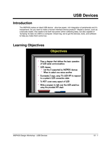
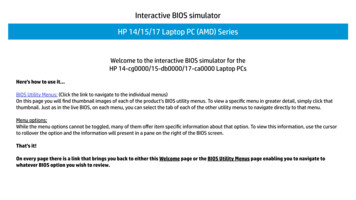
Setup 1Setup with a single TRACE32 PowerView instance running on the same host as the back-end: There are two configuration options: For step-by-step instructions on how to configure the above setup in T32Start, see StartTRACE32 Session via T32Start. For instructions on how to manually create a configuration file for the above setup, see StartTRACE32 Session without T32Start.Setup 2Setup with multiple TRACE32 PowerView instances (AMP) running on the same host as the back-end: There are two configuration options: For step-by-step instructions on how to configure the above setup in T32Start, see StartTRACE32 Session via T32Start. For instructions on how to manually create a configuration file for the above setup, see StartTRACE32 Session without T32Start. 1989-2022 LauterbachDebugging via USB User s Guide 9
Setup 3Setup with multiple TRACE32 PowerView instances (AMP) running on another host: ! There are two configuration options: For step-by-step instructions on how to configure the above setup in T32Start, see StartTRACE32 Session via T32Start. For instructions on how to manually create a configuration file for the above setup, see StartTRACE32 Session without T32Start. 1989-2022 LauterbachDebugging via USB User s Guide 10
Start the TRACE32 Session via T32Start Navigate to the TRACE32 system directory (by default c:\t32) and double-click /bin/windows/t32start.exe.Debug Environment for Setup 1 (Single Instance)1.In the T32Start window, right-click Configuration Tree, point to Add, and then selectConfiguration.A tree item named Configuration number is displayed.2.Press F2 to rename the new Configuration number tree item to a meaningful name, forexample, hostmci setup1.MCI Lib Debugger and Target3.Right-click the renamed tree item, point to Add, and then select MCI Lib Debugger.4.Click the little triangle next to MCI Lib Debugger to expand the tree node and navigate to Target.5.Right-click Target, and then select the target name you want from the Target drop-down list.6.Configure the Advanced Settings as required by your environment. See “Default AdvancedSettings” (app t32start.pdf) for more details.7.Click Save when you are done. 1989-2022 LauterbachDebugging via USB User s Guide 11
8.Click Start in order to start the debug session. A TRACE32 PowerView instance opens.Debug Environment for Setup 2 (Integrated Server)1.In the T32Start window, right-click Configuration Tree, point to Add, and then selectConfiguration.A new tree item named Configuration number is displayed.2.Press F2 to rename the tree item to a meaningful name, for example, hostmci setup2.MCI Server and Server Settings (Setup 2)3.Right-click the renamed tree item, point to Add, and then select MCI Server.4.Navigate from MCI Server to Server Settings by clicking the little triangles next to the tree items.5.Under Server Settings, make these settings:-Node Name / IP Address: Leave empty or type localhost-Port: Type any free port number-Dedicated: no 1989-2022 LauterbachDebugging via USB User s Guide 12
MCI Server Debugger and Target (Setup 2)6.Click the MCI Server tree item, point to Add, and then select MCI Server Debugger.7.Click the little triangle next to MCI Server Debugger to navigate to Target.8.Right-click Target, and then select the target name you want from the Target drop-down list.9.Repeat the steps in this section for each MCI Server Debugger required for your project.10.Configure the Advanced Settings as required by your environment. See “Default AdvancedSettings” (app t32start.pdf) for more details.11.Click Save when you are done.12.Click Start in order to start the debug session. A TRACE32 PowerView instance opens. 1989-2022 LauterbachDebugging via USB User s Guide 13
Debug Environment for Setup 3 (Dedicated Server)1.In the T32Start window, right-click Configuration Tree, point to Add, and then selectConfiguration.A tree item named Configuration number is displayed.2.Press F2 to rename the tree item to a meaningful name, for example, hostmci setup3.MCI Server and Server Settings (Setup 3)3.Right-click the renamed tree item, point to Add, and then select MCI Server.4.Navigate from MCI Server to Server Settings by clicking the little triangles next to the tree items.5.Under Server Settings, make these settings:-Node Name / IP Address: Type IP address of the workstation where t32mciserver runs-Port: Type any free port number-Dedicated: yes 1989-2022 LauterbachDebugging via USB User s Guide 14
MCI Server Debugger and Target (Setup 3)6.Click the MCI Server tree item, point to Add, and then select MCI Server Debugger.7.Click the little triangle next to MCI Server Debugger to navigate to Target.8.Right-click Target, and then select the target name you want from the Target drop-down list.9.Repeat the steps in this section for each MCI Server Debugger required for your project.10.Configure the Advanced Settings as required by your environment. See “Default AdvancedSettings” (app t32start.pdf) for more details.11.Click Save when you are done.12.Click Start in order to start the debug session. A TRACE32 PowerView instance opens. 1989-2022 LauterbachDebugging via USB User s Guide 15
Start the TRACE32 Session without T32StartIf you work on Linux or you do not want to use T32Start.exe, then you can manually create or edit yourTRACE32 configuration file.For more information about the TRACE32 configuration file, refer to “Configuration File”(training debugger.pdf).To make the settings in the configuration file:1.Open your TRACE32 configuration file (by default it is trace32 directory /config.t32),2.Proceed with one of the following three chapters, depending on which scenario you have chosenin chapter “Overview of Configuration Scenarios”.Debug Environment for Setup 1 (Single Instance)Modify the configuration file (e.g. config.t32) as follows:PBI MCILIB; configure software-only debuggingDebug Environment for Setup 2 (Integrated Server)Modify the configuration file (e.g. config.t32) as follows:PBI MCISERVERPORT 30000INSTANCE AUTO; configure software-only debugging and open; server at 30000 for the first instance.; consecutive number of instance or AUTODebug Environment for Setup 3 (Dedicated Server)Start t32mciserver on the simulation host:./t32mciserver port 30000; start t32mciserver at port 30000Modify the config.t32 file as follows:PBI MCISERVERNODE 192.168.0.1PORT 30000INSTANCE AUTODEDICATED 1989-2022 Lauterbach;;;;;set up connection to t32mciserverconnect to IP 192.168.0.1at port 30000consecutive number of instancesavoid to fall into Setup2 caseDebugging via USB User s Guide 16
To start TRACE32 PowerView with a specific config file, use e.g.:bin/pc linux/t32marm -c config.t32 1989-2022 LauterbachDebugging via USB User s Guide 17
TroubleshootingThe following describes some possible error scenarios, along with suggestions how to resolve them:Communication problem While attempting to connect to the target via TRACE32 PowerView by going into SYStem.Up, thefollowing error occurs:debug port failCould not get the device handle (error -5)Could not connect to this device: VID xxxx, PID xxxx (error -5) (Possible) solution: This error indicates a communication problem with the device. Especiallyfor USB3.x this output can indicate problems with the used USB cable or chipset.-Please use high-quality USB cables, the length should be as short as possible.-Double check if you have chosen the correct USB cable for the desired USB device. For moredetails, see chapter “System Requirements”.-Check if there is a firmware upgrade for your host USB chipset available.-Connect the device to another USB port. There is a chance that other ports are connected toanother type of USB chipset that might fully support all USB features. 1989-2022 LauterbachDebugging via USB User s Guide 18
Select a USB Device via the GUIThe following step-by-step procedure describes how to select a USB device for debugging by using theTRACE32 PowerView GUI. All steps described below can alternatively also be executed via the TRACE32command line.Remember that USB debugging is not available for all architectures.Prerequisites: You have started TRACE32, as described in “Start a TRACE32 Session for USB Debugging”,page 8. You have selected the CPU type of the target (SYStem.CPU). You have chosen the debug port (SYStem.CONFIG.DEBUGPORT). For more information aboutthis architecture-specific command, please refer to your Processor Architecture Manual.To select a USB device via the TRACE32 PowerView GUI:1.Open the SYStem.CONFIG.state window by typing at the TRACE32 command line:SYStem.CONFIG.state2.In the SYStem.CONFIG.state window, click the USB tab.3.Under USB, click the SELect button to open the SYStem.CONFIG.USB.SELect.view window. 1989-2022 LauterbachDebugging via USB User s Guide 19
4.From the SHOWDEVice drop-down list, select ALL to list all USB devices.5.Search for the desired USB device in the device tree.In the Interface Type column of the chosen device, right-click and then select the TRACE32 interfacetype from the popup menu, e.g. debug.The values are transferred to the USB tab of the SYStem.CONFIG.state window and displayedunder debug interface.Result: You have successfully selected an interface of a USB device. It can now be used for the chosenpurpose (e.g. debug, trace, or DMA). 1989-2022 LauterbachDebugging via USB User s Guide 20
Select a USB Device via the TRACE32 CommandsThere are three commands that allow to identify the USB target device based on certain parameters. Inaddition, the commands are used to configure the assignment of TRACE32 interface type to USB deviceinterface. This assignment defines that a particular interface of the USB device is either reserved fordebugging or tracing or DMA in TRACE32.The three commands are: SYStem.CONFIG.USB.SET SYStem.CONFIG.USB.SETDEVice SYStem.CONFIG.USB.SETBusPortWhile all three commands have the same purpose, SYStem.CONFIG.USB.SET can be seen as the“generic” command that allows to set all available parameters for the description of a device. The commandsSYStem.CONFIG.USB.SETDEVice and SYStem.CONFIG.USB.SETBusPort can be seen as subsets ofSYStem.CONFIG.USB.SET, which only need a small number of predefined parameters.The decision which command is the most suitable one mainly depends on the amount and the properties ofUSB devices that are currently connected to the host PC. In more complex scenarios with multiple similar oreven identical USB devices, the SYStem.CONFIG.USB.SET command is recommended.The configuration for a USB device can also be made at a point in time when the device is not attached tothe host PC (yet). In this case, the configuration will be displayed in the SYStem.CONFIG.state /USBwindow as “configured but not attached”. As soon as a device gets connected that uniquely matches thepreviously made configuration, the status of the TRACE32 interface type will be updated and it will bedisplayed as “attached”. See the chapter SYStem.CONFIG.state /USB for more details. 1989-2022 LauterbachDebugging via USB User s Guide 21
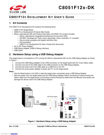
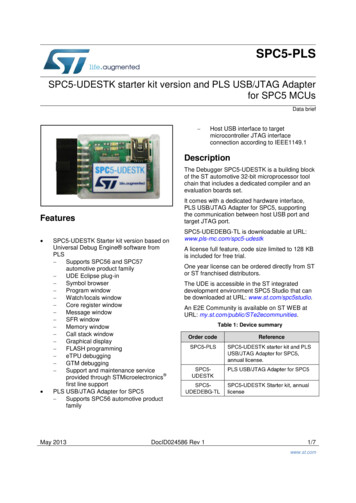
USB Specific SYStem.CONFIG CommandsSYStem.CONFIG.stateFormat:Open configuration window for USB debuggingSYStem.CONFIG.state /USBThe SYStem.CONFIG.state /USB tab provides an overview of the USB configuration and its status [F]. Itdisplays: Supported TRACE32 interface types USB device configuration for a certain interface type Status of each interface typeABGDCFEA USB tab in the SYStem.CONFIG.state window.B Buttons for the most important SYStem.CONFIG.USB commands.C Resets the configuration of the respective interface type (executes SYStem.CONFIG.USB.RESet).D Copies the current configuration settings to the TRACE32 command line (will be printed asSYStem.CONFIG.USB.SET command).E Edit boxes that allow to set identification parameters for the desired target device. Therefore, eachedit box represents one (optional) parameter of the SYStem.CONFIG.USB.SET command. 1989-2022 LauterbachDebugging via USB User s Guide 22
F Indicator for the status of the respective interface type. Possible states are: not configured: No configuration for this interface type has been made yet. configured, not attached: A configuration for this interface type has been made, but theparameters do not match any USB device that is currently attached to the host PC. configured (no unique device): The configuration parameters for this interface type can bematched to more than one of the USB devices that are connected to the host PC. To solvethis, either remove unnecessary USB devices, or add more configuration parameters inorder to make the description unique. configured (no unique interface): The configuration parameters for the interface typematch exactly one attached USB device. However, the selection of the USB interface is notunique. Possible reasons are:-The selected USB device has more than one interface, and the interface parameter isnot set.- At least two configurations (for different interface types) were made for the same USBinterface of the same device. Note that each USB interface can only be assigned to asingle type.attached (unused): The configuration parameters for this USB mode match exactly oneattached USB device, and also match a unique device interface. This configuration is sufficient, however the interface type is currently not in use.attached (in use): The configuration parameters for this interface type match exactly oneattached USB device, and also match a unique device interface. The interface type is currently in use.G The entire debug interface box displays the configuration state of the TRACE32 interface typeDebug. 1989-2022 LauterbachDebugging via USB User s Guide 23
SYStem.CONFIG.USBUSB configurationUsing the command group SYStem.CONFIG.USB, you can configure TRACE32 in order to ensure properidentification of the desired target device. In addition, the command group allows to specify which of thetarget’s various USB device interfaces shall be used for which purpose (Debug, Trace, or DMA).Parameters and ExpressionsThe following table describes parameters and expressions that are used in the SYStem.CONFIG.USBcommands and on the graphical user interface TRACE32 PowerView: type Specify the TRACE32 interface type you want to assign to the selectedUSB device interface.Available TRACE32 interface types are Debug, Trace, or DMA.Depending on the target architecture, only a subset of the TRACE32interface types can be selected.NOTE: To select a USB device interface, specify its interface number ,as explained below.InterFace interface number The interface number allows you to assign a particular USB interfacedevice to a TRACE32 interface type .For an example, see SYStem.CONFIG.USB.SET. In this example, theUSB device interface 1. is assigned to the TRACE32 interface type Debug, i.e. the USB device interface 1. is now reserved for debugging(and not for tracing or DMA).Bus port topologyBusPort busport USB port topology representation. Physical position of the host PC USBport to which the target is connected in the bus. busport syntax:The string must match the pattern “(bXpY) ”, with X and Y being integersfrom 0-9999.Valid examples: “b2p3”, “b12p18”, "b18p1b33p39b2p73".As an alternative to the manual data input, you can proceed as describedin “Select a USB Device via the GUI”, page 19.DeviceNum device number 1989-2022 LauterbachSee Ident. device #Debugging via USB User s Guide 24
Ident. device #Identical device number. If multiple identical USB devices are connectedto the computer, it is not trivial any more to distinguish them by their'usual' identification parameters such as vendor ID or product ID, asthese parameters are identical as well.In order to ease the differentiation in such scenarios, each identicaldevice is assigned its own 'identical-device number' by TRACE32.This number is an ID that is unique for each of the attached devices. TheIDs start at 0.Interface classNumeric description of the USB interface class.Interface protocolNumeric description of the USB interface protocol.Interface subclassNumeric description of the USB interface subclass.Product IDPID pid ID of the device, which is contained in the device descriptor of the USBdevice.Vendor IDVID vid ID of the device vendor, which is contained in the device descriptor of theUSB device.Vendor nameName of the device vendor.See also SYStem.CONFIG.USB.RESet SYStem.CONFIG.USB.SET SYStem.CONFIG.USB.SETDEFaults 1989-2022 Lauterbach SYStem.CONFIG.USB.SELect SYStem.CONFIG.USB.SETBusPort SYStem.CONFIG.USB.SETDEViceDebugging via USB User s Guide 25
SYStem.CONFIG.USB.RESetReset configuration of interface typeFormat:SYStem.CONFIG.USB.RESet [ type ] type :ALLDebugTraceDMAResets the configuration of a selected or all TRACE32 interface types.ALLResets the configuration for all TRACE32 interface types (such asDebug, Trace, etc.). Any USB device that has already been selected willbe unselected.DebugResets the configuration for the debug interface.TraceResets the configuration for the trace interface.DMAResets the configuration for the DMA interface (Direct Memory Access).See also SYStem.CONFIG.USB 1989-2022 LauterbachDebugging via USB User s Guide 26
SYStem.CONFIG.USB.SELectConnected USB devicesUsing the SYStem.CONFIG.USB.SELect command group, you can display a list of connected USBdevices in the form of a tree structure, filter the list, as well as expand and collapse the nodes of the USBdevice tree.See also SYStem.CONFIG.USB.SELect.CollapseAll SYStem.CONFIG.USB.SELect.SHOWDEVice SYStem.CONFIG.USBSYStem.CONFIG.USB.SELect.view SYStem.CONFIG.USB.SELect.ExpandAll SYStem.CONFIG.USB.SELect.viewList connected USB devices[Window Description]Format:SYStem.CONFIG.USB.SELect.view [/ option ] option :SpotLightOpens the USB device selection window, displaying a list of all USB devices that are currently connected tothe host computer. To help you identify and distinguish the USB devices, the tree of each device and itsvarious interfaces displays additional information (partially obtained from the USB descriptors): Each device is described by its vendor name, vendor ID, product ID, identical device number, andbus port topology. Each interface of a device is described by its class, subclass, protocol, and endpoints.For information about these parameters, see SYStem.CONFIG.USB.SpotLightHighlights recently attached USB devices.The USB device that was most recently attached to the host PC ishighlighted in dark red. The USB device that was attached second to lastis highlighted a little bit lighter.This works up to a level of 4 USB devices. The window can only highlightdevices that get attached while the window is open. 1989-2022 LauterbachDebugging via USB User s Guide 27
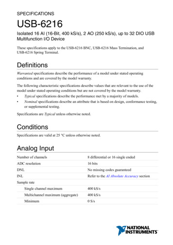
Description of the SYStem.CONFIG.USB.SELect Window:In the SYStem.CONFIG.USB.SELect window, you can perform the following actions: Filter the USB devices [B]. Expand and collapse the USB device tree [C]. Assign an interface of a USB device to an interface type (right-click and select an entry in the popupmenu [E]).BCDAFEGA USB device in tree structureB Filter option for USB devices: SUPPORTED - show only supported USB devices (i.e. devices that match the supportedinterface class) CPUVENDOR - show only USB devices of CPU vendor ALL - show all USB devicesC Expands / collapses all tree elements.D Status of USB interface: “bound” if the interface is currently in use “unbound” if the interface is not used.E Interface type assignment for a specific interface. The available types are debug, trace, and DMA.F Parameters of the USB device.G Interface parameters of the USB device.See also SYStem.CONFIG.USB.SELect 1989-2022 LauterbachDebugging via USB User s Guide 28
SYStem.CONFIG.USB.SELect.SHOWDEViceFilter the USB device treeFormat:SYStem.CONFIG.USB.SELect.SHOWDEVice filter filter :SUPPORTED CPUVENDOR ALLFilters the tree structure of the USB devices displayed in the SYStem.CONFIG.USB.SELect.view window.USB devices matching the filter criterion are visible. USB devices not matching the filter criterion aretemporarily hidden.SUPPORTEDLists only USB devices that match the supported USB interface class.CPUVENDORLists only USB devices that match the vendor of the selected target CPU,i.e., the CPU selected with the SYStem.CPU command.ALLLists all attached USB devices.See also xpandAllFormat:Expand treeSYStem.CONFIG.USB.SELect.ExpandAllExpands all nodes of the USB device tree in the SYStem.CONFIG.USB.SELect.view window.See also SYStem.CONFIG.USB.SELect 1989-2022 LauterbachDebugging via USB User s Guide 29
e treeSYStem.CONFIG.USB.SELect.CollapseAllCollapses all nodes of the USB device tree in the SYStem.CONFIG.USB.SELect.view window.See also SYStem.CONFIG.USB.SELect 1989-2022 LauterbachDebugging via USB User s Guide 30
SYStem.CONFIG.USB.SETConfigure all parameters of USB deviceFormat:SYStem.CONFIG.USB.SET type [/ option ] type :Debug Trace DMA option :InterFace interface number VID vid PID pid BusPort busport DeviceNum device number Configures a USB device based on all parameters. type For a description of the parameters type , etc., seeSYStem.CONFIG.USB.Example: This example contains all of the optional parameters. Depending on how many devices areconnected to the PC and what
MCI Server and Server Settings (Setup 2) 3. Right-click the renamed tree item, point to Add, and then select MCI Server. 4. Navigate from MCI Server to Server Settings by clicking the little triangles next to the tree items. 5. Under Server Settings, make these settings:-Node Name / IP Address: Leave empty or type localhost-Port: Type any free .