Transcription
Configuring Messagesand Alarms in WinCC(TIA Portal) –Extension withS7-1200/S7-1500WinCC V14 iew/62121503SiemensIndustryOnlineSupport
Legal informationLegal informationUse of application examplesApplication examples illustrate the solution of automation tasks through an interaction of severalcomponents in the form of text, graphics and/or software modules. The application examples area free service by Siemens AG and/or a subsidiary of Siemens AG (“Siemens”). They are nonbinding and make no claim to completeness or functionality regarding configuration andequipment. The application examples merely offer help with typical tasks; they do not constitutecustomer-specific solutions. You yourself are responsible for the proper and safe operation of theproducts in accordance with applicable regulations and must also check the function of therespective application example and customize it for your system.Siemens grants you the non-exclusive, non-sublicensable and non-transferable right to have theapplication examples used by technically trained personnel. Any change to the applicationexamples is your responsibility. Sharing the application examples with third parties or copying theapplication examples or excerpts thereof is permitted only in combination with your own products.The application examples are not required to undergo the customary tests and quality inspectionsof a chargeable product; they may have functional and performance defects as well as errors. It isyour responsibility to use them in such a manner that any malfunctions that may occur do notresult in property damage or injury to persons. Siemens AG 2018 All rights reservedDisclaimer of liabilitySiemens shall not assume any liability, for any legal reason whatsoever, including, withoutlimitation, liability for the usability, availability, completeness and freedom from defects of theapplication examples as well as for related information, configuration and performance data andany damage caused thereby. This shall not apply in cases of mandatory liability, for exampleunder the German Product Liability Act, or in cases of intent, gross negligence, or culpable loss oflife, bodily injury or damage to health, non-compliance with a guarantee, fraudulentnon-disclosure of a defect, or culpable breach of material contractual obligations. Claims fordamages arising from a breach of material contractual obligations shall however be limited to theforeseeable damage typical of the type of agreement, unless liability arises from intent or grossnegligence or is based on loss of life, bodily injury or damage to health. The foregoing provisionsdo not imply any change in the burden of proof to your detriment. You shall indemnify Siemensagainst existing or future claims of third parties in this connection except where Siemens ismandatorily liable.By using the application examples you acknowledge that Siemens cannot be held liable for anydamage beyond the liability provisions described.Other informationSiemens reserves the right to make changes to the application examples at any time withoutnotice. In case of discrepancies between the suggestions in the application examples and otherSiemens publications such as catalogs, the content of the other documentation shall haveprecedence.The Siemens terms of use (https://support.industry.siemens.com) shall also apply.Security informationSiemens provides products and solutions with industrial security functions that support the secureoperation of plants, systems, machines and networks.In order to protect plants, systems, machines and networks against cyber threats, it is necessaryto implement – and continuously maintain – a holistic, state-of-the-art industrial security concept.Siemens’ products and solutions constitute one element of such a concept.Customers are responsible for preventing unauthorized access to their plants, systems, machinesand networks. Such systems, machines and components should only be connected to anenterprise network or the internet if and to the extent such a connection is necessary and onlywhen appropriate security measures (e.g. firewalls and/or network segmentation) are in place.For additional information on industrial security measures that may be implemented, please emens’ products and solutions undergo continuous development to make them more secure.Siemens strongly recommends that product updates are applied as soon as they are availableand that the latest product versions are used. Use of product versions that are no longersupported, and failure to apply the latest updates may increase customer’s exposure to cyberthreats.To stay informed about product updates, subscribe to the Siemens Industrial Security RSS Feedat: http://www.siemens.com/industrialsecurity.Alarms in WinCC (TIA Portal)Entry ID: 62121503, V2.0, 05/20182
Table of ContentsTable of ContentsLegal information . 21Introduction . 41.11.21.31.42Configuring Alarms in WinCC Basic/Comfort/Advanced . 72.12.22.2.12.2.22.32.3.12.3.22.3.32.42.52.63 Siemens AG 2018 All rights reservedConfiguring user-defined alarms . 35Configuring system-defined alarms . 35Configuring system events (S7-1200, S7-1500) . 35Configuring CPU system diagnostic alarms (S7-1500) . 41Configuring controller alarms . 43Configuring Program Alarm (S7-1500) . 43Configuring Get AlarmState (S7-1500) . 45Configuring Gen UsrMsg (S7-1200, S7-1500) . 45Using alarm classes . 46Using alarm groups . 47Acknowledgment model . 48Alarm without acknowledgment . 48Alarm with single acknowledgment . 48Alarm with double acknowledgment . 49General information about acknowledgment models . 51Valuable Information . 524.14.1.14.1.24.1.34.1.45Configuring user-defined alarms . 7Configuring system-defined alarms . 8Configuring system events (S7-1200, S7-1500) . 8Configuring CPU system diagnostic alarms (S7-1500) . 12Configuring controller alarms . 15Configuring Program Alarm (S7-1500) . 15Configuring Get AlarmState (S7-1500) . 22Configuring Gen UsrMsg (S7-1200, S7-1500) . 26Using alarm classes . 31Using alarm groups . 32Acknowledgment model . 33Configuring Alarms in WinCC Professional . 3.6.23.6.33.6.44Overview. 4How the application works. 5Scope . 5Components used . 6Basics . 52Overview of the alarm procedures . 52User-defined alarms . 53System-defined alarms. 54Availability of alarm procedures . 55Appendix . 565.15.25.3Service and Support . 56Links and literature . 57Change documentation . 58Alarms in WinCC (TIA Portal)Entry ID: 62121503, V2.0, 05/20183
1 Introduction1Introduction1.1OverviewMotivationThis documentation describes the configuration of messages and alarms in WinCC(TIA Portal) in conjunction with theS7-1200/S7-1500 controller families.Application-specific implementationThe application-specific implementation is based on the documentation“Configuration of Messages and Alarms in WinCC (TIA Portal)” in conjunction withthe S7-300/S7-400 controller families of this application example.The basics and selected chapters explicitly refer to this documentation as thecontent and the configuration scope are identical.The application example is a supplement to the manual and TIA Portal’s OnlineHelp.Required knowledge Siemens AG 2018 All rights reservedBasic knowledge of WinCC (TIA Portal).NoteThe SITRAIN courses “SIMATIC WinCC on the machine level in the TIA Portal”and “SIMATIC WinCC SCADA in the TIA Portal” teach the basics of WinCC. SIMATIC WinCC maschinennah im TIA Portal (de)SIMATIC WinCC on the machine level in the TIA Portal (en) SIMATIC WinCC SCADA im TIA Portal (de)SIMATIC WinCC SCADA in the TIA Portal (en)The SITRAIN courses “SIMATIC programming 1 in the TIA Portal” and “SIMATICS7-1200 basic course” teach the basics of STEP 7. SIMATIC Programmieren 1 im TIA Portal (de)SIMATIC programming 1 in the TIA Portal (en) SIMATIC S7-1200 Basiskurs (de)SIMATIC S7-1200 basic course (en)Alarms in WinCC (TIA Portal)Entry ID: 62121503, V2.0, 05/20184
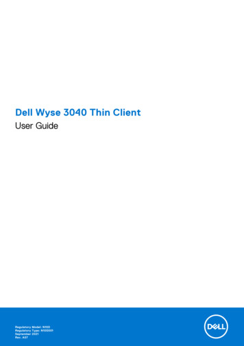
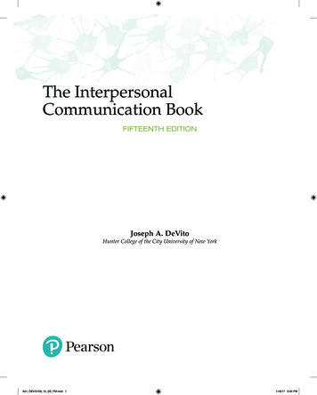
1 Introduction1.2How the application worksDuring operation of a plant, it is essential to visually output information aboutoperating states, faults and individual processes on an HMI operator panel. Inconjunction with the SIMATIC S7-1200/S7-1500 controllers, WinCC (TIA Portal)alarm logging offers an appropriate alarm procedure for each of these pieces ofinformation.This application provides you with: An overview of the different alarm procedures in WinCC Support in selecting the right alarm procedure for your use case and hardware(S7-1200/S7-1500) Detailed configuration instructions for the different types of alarms in WinCCand STEP 7 (TIA Portal)Figure 1-1TP1200E.g., S7-1500 Siemens AG 2018 All rights reservedAlarmPROFINET / IEE.g., ET200 SP1.3ScopeThis application example explains messages and alarms in WinCC (TIA Portal) inconjunction with the S7-1200/S7-1500 controller families.For more information about the alarm procedures with the S7-300/S7-400controllers, refer to the second PDF document for this application example.Alarms in WinCC (TIA Portal)Entry ID: 62121503, V2.0, 05/20185
1 Introduction1.4Components usedThe application was created with the following components:Hardware componentsTable 1-1Component Siemens AG 2018 All rights reservedNoteNo.Article numberSIMATIC CPU 1513-1 PN16ES7513-1AL01-0AB0Memory card, 24 Mbytes16ES7954-8LF02-0AA0SIMATIC HMI TP1200Comfort16AV2124-0MC01-0AX0NoteAlternatively, anyother CPU from theS7-1500 family can beused; the onlyrequirement is tochange the device inthe configuration.Alternatively, anyother Comfort Panelcan be used (devicechange required).When using a CPU from the S7-1200 family, the scope of possible alarm types issignificantly restricted compared to a CPU from the S7-1500 family.Software componentsTable 1-2ComponentNo.Article numberSTEP 7 Professional V14 SP1 (TIA Portal)16ES7822-1.04-.WinCC Professional V14 SP1 (TIA Portal)16AV210.- .4-0WinCC Runtime Professional V14 SP1 (TIA Portal)16AV2105-. 4-0Alarms in WinCC (TIA Portal)Entry ID: 62121503, V2.0, 05/20186
2 Configuring Alarms in WinCC Basic/Comfort/Advanced2Configuring Alarms in WinCCBasic/Comfort/AdvancedAs a supplement to the manual (“Working with alarms” chapter), this sectiondescribes the configuration of system-defined alarms and controller alarms. Thisincludes the configuration of user-defined alarms.Required software components WinCC Basic/Comfort/Advanced V14 SP1 (TIA Portal) STEP 7 Professional V14 SP1 (TIA Portal)RequirementA WinCC (TIA Portal) project exists with a created connection between theoperator panel and the controller. Siemens AG 2018 All rights reserved2.1Configuring user-defined alarmsIn WinCC Basic/Comfort/Advanced, the configuration of user-defined alarms(discrete alarms and analog alarms) is independent of the controller used. For adetailed description of configuring user-defined alarms, refer to the followingapplication example:“Configuration of Messages and Alarms in WinCC” In addition, you will find adetailed description in the “Configuring discrete alarms” and “Configuring analogalarms” chapters of the WinCC Advanced V14 system manual.Alarms in WinCC (TIA Portal)Entry ID: 62121503, V2.0, 05/20187
2 Configuring Alarms in WinCC Basic/Comfort/Advanced2.2Configuring system-defined alarms2.2.1Configuring system events (S7-1200, S7-1500)By default, system events are stored in the HMI for different languages. If you wantto translate system events into other languages, you must first import the texts intothe project.Importing system eventsImporting system events is only necessary for projects that were newly created orwhen the system events have not yet been imported.Table 2-1 Siemens AG 2018 All rights reservedNo.Action1.In the project tree, go to the folder of the operator panel you created and open the“HMI alarms”.2.Open the “System events” tab.3.Confirm the next dialog to import the “system events”.4.Importing the system events is now complete.Alarms in WinCC (TIA Portal)Entry ID: 62121503, V2.0, 05/20188
2 Configuring Alarms in WinCC Basic/Comfort/AdvancedDisplay of system events on the operator panel in RuntimeThe following table provides the instructions for configuring an alarm view. This is astatic element (always visible) that you permanently configure into a screen.NoteAside from a static alarm view, you have the option to dynamically output alarmsusing an alarm window. It is configured in the “global screen” of the HMI andappears only when an alarm occurs.For more information, refer to the WinCC manual, chapter “Configuring an alarmwindow”.Table 2-2 Siemens AG 2018 All rights reservedNo.Action1.Open the start screen of your operator panel.2.In the “Toolbox” task card, go to “Controls” and select the “Alarm view”.3.Use drag and drop to move the “Alarm view” to your start screen and resize it asrequired.4.In the “Alarm view” properties, check “System” to display system events on theoperator panel.For more information about configuring an alarm view, refer to the WinCCBasic/Comfort/Advanced system manual, “Configuring an alarm view”.Alarms in WinCC (TIA Portal)Entry ID: 62121503, V2.0, 05/20189
2 Configuring Alarms in WinCC Basic/Comfort/AdvancedDefining the display duration for system eventsTable 2-3No.ActionIn the project tree, go to the folder of the operator panel you created and open the“Runtime settings”.2.Open the “Alarms” menu. Siemens AG 2018 All rights reserved1.In “System events Display duration in seconds”, enter the display duration forsystem events on the operator panel.NoteIf you want the system events to be permanently pending, set the display duration to“0” seconds.3.The display duration settings for system events are now complete.Alarms in WinCC (TIA Portal)Entry ID: 62121503, V2.0, 05/201810
2 Configuring Alarms in WinCC Basic/Comfort/AdvancedChanging alarm texts for system eventsThe alarm texts of system events can be changed or customized if necessary. Theassociated alarm numbers cannot be changed.NoteChanging system events changes clearly defined alarms, which may result inmisinterpretations.The imported alarms are part of the manual / online help.When a change is made, the changed alarms no longer match thedocumentation.Table 2-4 Siemens AG 2018 All rights reservedNo.Action1.In the project tree, go to the folder of the operator panel you created and open the“HMI alarms”.2.Open the “System events” tab.Select the system event whose alarm text you want to change.Alarms in WinCC (TIA Portal)Entry ID: 62121503, V2.0, 05/201811
2 Configuring Alarms in WinCC Basic/Comfort/AdvancedNo.3.ActionIn the Inspector window, open the “Properties Properties General” tab.In “Alarm text”, change the alarm text of the system event.NoteWhen changing an alarm text, the number of wildcards must not be modified.Example of a wildcard: %14.2.2.2Changing the alarm text for the system event is now complete.Configuring CPU system diagnostic alarms (S7-1500) Siemens AG 2018 All rights reservedThe following section describes the configuration of the display of systemdiagnostic alarms of an S7-1500 CPU on an operator panel.Settings in STEP 7Table 2-5No.Action1.In the project tree, open the “Device configuration” of your CPU.2.In the device view, select the CPU on the rack.Alarms in WinCC (TIA Portal)Entry ID: 62121503, V2.0, 05/201812
2 Configuring Alarms in WinCC Basic/Comfort/AdvancedNo. Siemens AG 2018 All rights reserved3.ActionIn the Inspector window, open the “Properties General System diagnostics” tab.The “Activate system diagnostics for this device” check box is checked by defaultand cannot be unchecked.Optional:Depending on your requirements, “Alarm settings” in the bottom part of theInspector window allows you to customize the alarms and alarm classes of therespective categories.4.In the project tree, right-click the CPU. From the context menu, select “Compile Hardware (rebuild all)”.5.The settings in STEP 7 are now complete.Alarms in WinCC (TIA Portal)Entry ID: 62121503, V2.0, 05/201813
2 Configuring Alarms in WinCC Basic/Comfort/AdvancedSettings in WinCC Basic/Comfort/AdvancedTable 2-6No.ActionIn the project tree, open the “Runtime settings” of your operator panel.2.In “Alarms System events”, check the “S7 diagnostic alarms” check box. Siemens AG 2018 All rights reserved1.If you want to display the associated alarm text in addition to the alarm number,check the “With event text” check box as well.3.In the next step, create an “alarm view” in a screen of your operator panel.Alarms in WinCC (TIA Portal)Entry ID: 62121503, V2.0, 05/201814
2 Configuring Alarms in WinCC Basic/Comfort/AdvancedNo.4.ActionIn the “Alarm view” properties, go to “Properties General” and check the“Diagnosis events” alarm class to display system diagnostic alarms in WinCC. Siemens AG 2018 All rights reservedNoteDepending on the CPU’s alarm class (e.g., in step 3 of Table 2-5), it may beadditionally necessary to check the “Acknowledgement” or “No Acknowledgement”alarm classes.5.Transfer the project to the operator panel.The settings in WinCC are now complete.For more information about configuring an alarm view, refer to the WinCCBasic/Comfort/Advanced system manual, “Configuring an alarm view”.NoteFor information about system diagnostics and system diagnostics options, referto the following application example:“System Diagnostics with S7-1500 and TIA Portal”2.3Configuring controller alarms2.3.1Configuring Program Alarm (S7-1500)The “Program Alarm: Generate program alarm with associated values” instructionmonitors a signal and generates an incoming program alarm when the signal at theSIG parameter changes from 0 to 1. When the signal changes from 1 to 0, itgenerates an outgoing program alarm. Whether or not the alarm requiresacknowledgment depends on the configured alarm class. By default, it is notnecessary to acknowledge the block.You can append up to ten associated values to the program alarm. Each alarm,both incoming and outgoing, is provided with a time stamp.Alarms in WinCC (TIA Portal)Entry ID: 62121503, V2.0, 05/201815
2 Configuring Alarms in WinCC Basic/Comfort/AdvancedParameters of the Program Alarm alarm blockTable 2-7ParameterSIGDeclarationData typeInputBOOLMemory areaI, Q, M, D, L, T, Cor constantDescriptionThe signal to be monitored. Positive signal edge: Anincoming program alarm isgenerated Negative signal edge: Anoutgoing program alarm isgeneratedInputLDTM, D, L or constantThis parameter is used to providean alarm with a time stamp, forexample, from an input signal witha distributed stamp. The timevalue must always be specified insystem time (i.e. UTC), as this isthe time used for timesynchronization throughout theplant. “Not assigned” means thatthe system time of the CPUwill be used as the interrupttime stamp when a signalchange occurs (default). Any system time input will beused as the interrupt timestamp when a signal changeoccurs.Note: If you want an interrupt to betime-stamped with local time, aconversion block must beconnected in series to convertlocal time to system time. This isthe only way to make sure that thetime stamp is shown correctly inthe interrupt display.SD iInputVARIANTI, Q, M, D, Li-th associated value (1 i 10)You can use binary numbers,integers, floating-point numbers orstrings as associated values.ErrorOutputBOOLI, Q, M, D, LError status parameterError TRUE indicates that anerror has occurred duringprocessing. The Status parameterdisplays the possible error cause.StatusOutputWORDI, Q, M, D, LStatus status parameterDisplays the error information (see“Error and Status parameters”). Siemens AG 2018 All rights reservedTIMESTAMPAlarms in WinCC (TIA Portal)Entry ID: 62121503, V2.0, 05/201816
2 Configuring Alarms in WinCC Basic/Comfort/AdvancedFor more information about the “Program Alarm” block, refer to the STEP 7 systemmanual, “Program Alarm: Generate program alarm with associated values” or thefollowing application example:“Diagnostics in User Program with S7-1500”Settings in STEP 7The following table shows the configuration steps necessary to create a programalarm in STEP 7.NoteThe STEP 7 configuration steps for the “Program Alarm” alarm block apply toboth the WinCC Basic/Comfort/Advanced visualization versions and WinCCProfessional.Table 2-8No.ActionFirst, create a global data block for storing and monitoring the values:Go to the created CPU and double-click “Program blocks Add new block”.2.From the dialog, select “Data block” and change the block’s name, if necessary.Confirm with “OK”. Siemens AG 2018 All rights reserved1.Alarms in WinCC (TIA Portal)Entry ID: 62121503, V2.0, 05/201817
2 Configuring Alarms in WinCC Basic/Comfort/Advanced Siemens AG 2018 All rights reservedNo.Action3.Insert four tags with the appropriate data types into the created data block to beable to interconnect the “Program Alarm” instruction.4.Proceed similarly to the first two steps to create a function block to be able to callthe “Program Alarm” instruction.5.Go to the “Instructions Extended Instructions” task card and open the “Alarming”folder.Alarms in WinCC (TIA Portal)Entry ID: 62121503, V2.0, 05/201818
2 Configuring Alarms in WinCC Basic/Comfort/AdvancedNo.ActionUse drag and drop to move the “Program Alarm” alarm block to an empty networkof the function block. Click “OK” to confirm the “call options”.7.Interconnect the inserted “Program Alarm” block with the tags from the data block. Siemens AG 2018 All rights reserved6.Alarms in WinCC (TIA Portal)Entry ID: 62121503, V2.0, 05/201819
2 Configuring Alarms in WinCC Basic/Comfort/AdvancedNo. Siemens AG 2018 All rights reserved8.9.ActionTo edit the alarms, go to the “Properties” tab and click Alarm. Here you can: Edit the alarm class, priority and alarm text (Basic settings) Select the display class, group ID and logging (Advanced settings) and define additional alarm texts.In the alarm text input window, right-click and select different options from thecontext window to specify the alarm texts in greater detail.NoteDue to the “@1%s@” string, the value of the SD 1 parameter is read out andoutput as a string.Alarms in WinCC (TIA Portal)Entry ID: 62121503, V2.0, 05/201820
2 Configuring Alarms in WinCC Basic/Comfort/AdvancedSettings in WinCC Basic/Comfort/AdvancedTable 2-9No.ActionIn the project tree, open the start screen of your operator panel.2.Create an alarm view.3.In the “Alarm view” properties, go to “Properties General” and check the“Acknowledgement ” and “No Acknowledgement” alarm classes to display systemprogram alarms in WinCC.4.Transfer the project to your operator panel.The settings in WinCC are now complete. Siemens AG 2018 All rights reserved1.For more information about configuring an alarm view, refer to the WinCCBasic/Comfort/Advanced system manual, “Configuring an alarm view”.Alarms in WinCC (TIA Portal)Entry ID: 62121503, V2.0, 05/201821
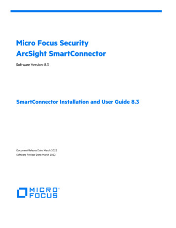
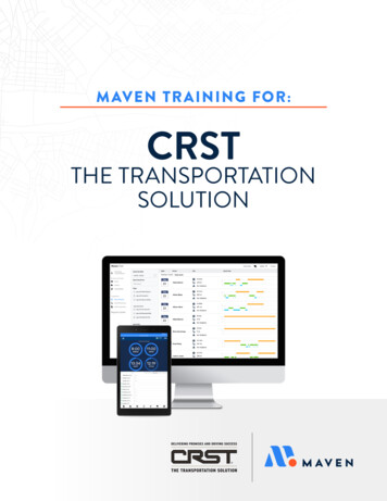
2 Configuring Alarms in WinCC Basic/Comfort/Advanced2.3.2Configuring Get AlarmState (S7-1500)The “Get AlarmState” instruction outputs the alarm state of a program alarm.NoteEach output alarm state refers to a program alarm that was created using the“Program Alarm” instruction.The “Alarm” input parameter defines which program alarm is output: Specify theinstance DB of the “Program Alarm” instruction whose alarm state you want tooutput.The “AlarmState” output parameter outputs the alarm state in a byte.Meaning of the individual bits of the “AlarmState” output parameter: Siemens AG 2018 All rights reservedFigure 2-1For more information about the “Get AlarmState” instruction, refer to the STEP 7system manual, “Get AlarmState: Output alarm status”.Alarms in WinCC (TIA Portal)Entry ID: 62121503, V2.0, 05/201822
2 Configuring Alarms in WinCC Basic/Comfort/AdvancedParameters of the Get AlarmState blockTable 2-10ParameterDeclarationAlarmInputData typeALARM BASEMemory areaDDescriptionInstance of the “Generate programalarm with associated values”instruction. Siemens AG 2018 All rights reserved Alarm.Messagetype Alarm AP, then the signal stateof the Ac bit is either 0 or 1 andthe signal state of the Ag bit is 1–not active: 0x86 (10000110)–active/not acknowledged:0x85 (1000 0101)–active/acknowledged: 0x87(1000 0111)–outgoing/not acknowledged:0x84 (10000100)Alarm.Messagetype Notify AP, then the signal stateof the Ac bit is either 0 or 1 andthe signal state of the Ag bit is 1-not active: 0x86 (10000110)-active: 0x85 (10000101)Alarm.Messagetype Inforeport AP, then the signalstate of both bits, Ac and Ag, is 1–Static: 0x86 (10000110)If the alarm is not active or an inforeport, the signal state of the S bit is0.AlarmStateOutputBYTEI, Q, M, D, LAlarm state as a bit fieldErrorOutputBOOLI, Q, M, D, LStatus parameter 0: No error 1: An error occurred whileexecuting the instruction.Detailed informationis output via the STATUSparameter.STATUSOutputWORDAlarms in WinCC (TIA Portal)Entry ID: 62121503, V2.0, 05/2018I, Q, M, D, LStatus parameterThe parameter is only set for theduration of one call. To display thestatus, you should therefore copySTATUS to a free data area.23
2 Configuring Alarms in WinCC Basic/Comfort/AdvancedConfiguring in STEP 7The following table shows you how to output the alarm state of a program alarm. Inorder to configure it, a program alarm must already have been created (asdescribed in chapter 2.3.1).NoteThe configuration steps for the “Get AlarmState” instruction apply to both theWinCC Basic/Comfort/Advanced visualization versions and WinCC Professional.Table 2-11 Siemens AG 2018 All rights reservedNo.Action1.Open the “ProgramAlarmTags” data block (see Table 2-8) and insert three tags withthe associated data types.2.Go to the “Instructions Extended Instructions” task card and open the “Alarming”folder.Alarms in WinCC (TIA Portal)Entry ID: 62121503, V2.0, 05/201824
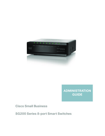
2 Configuring Alarms in WinCC Basic/Comfort/Advanced Siemens AG 2018 All rights reservedNo.Action3.Use drag and drop to move the “Get AlarmState” block to an empty network of thefunction block where the block for the Program Alarm is called.4.Interconnect the “Alarm” input parameter with the instance of the “Program Alarm”instruction. Then interconnect the block’s output parameters with the three createdtags of the data block.5.Download the configuration to your CPU.6.The program alarm is output as soon as the “Program Alarm” instruction receives a“True” signal state at the SIG input parameter. Then the “AlarmState” output of the“Get AlarmState” instruction displays the alarm based on the alarm class.Alarms in WinCC (TIA Portal)Entry ID: 62121503, V2.0, 05/201825
2 Configuring Alarms in WinCC Basic/Comfort/Advanced2.3.3Configuring Gen UsrMsg (S7-1200, S7-1500)The “Gen UsrMsg” instruction generates an alarm that is entered in the diagnosticbuffer. The Mode parameter allows you to select whether an incoming or outgoingalarm will be generated: Mode 1: generate incoming alarm Mode 2: generate outgoing alarmUse text lists and the appropriate text list entries to define the alarm contents. The“TextListID” and “TextID” parameters allow you to select the entry you want to writeto the diagnostic buffer. In the text lists, you can also define a
An overview of the different alarm procedures in WinCC Support in selecting the right alarm procedure for your use case and hardware (S7-1200/S7-1500) Detailed configuration instructions for the different types of alarms in WinCC and STEP 7 (TIA Portal) Figure 1-1 PROFINET / IE E.g., S7-1500 TP1200 E.g., ET200 SP Alarm 1.3 Scope