Transcription
DO-160 & MIL-STD-461GIndirect Lightning TestingMIG series
This document has beenoptimized for electronic mediaSmart navigation through technicalspecifications. Click the green links.Accredited CalibrationQuality at EMC PARTNER is based on an ISO 9001 management system.This is the foundation for an ISO 17025 accreditation verified by the SwissCalibration Service (SCS). SCS No. 146 is the accreditation number of EMCPARTNER AG. Locally accredited but recognized worldwide through affiliation with the ILAC organisation
WHEN GETTING RESULTS MATTERSTHERE IS STILL ONLY ONE CHOICEWESHALB BRAUCHT ES EINEN STYLE GUIDE ?Military and avionic testing is all about quality and reliability. The EMC PARTNER fullscale lightning test system fulfils these requirements.A flexible solution that includes:››››››››MIL-STD-461G: CS117, internal & external equipment test levelsRTCA DO-160: SECTION 22, Level 1 to 5EUROCAE ED-14: SECTION 22, Level 1 to 5OEM proprietary requirements based on DO-160 SECTION 22Providing world-class solutions to major aircraft OEMs and tier 1 suppliers for over 20years.3
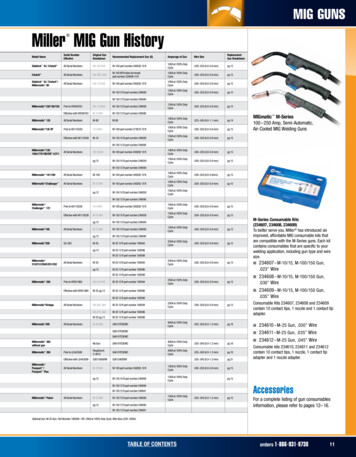
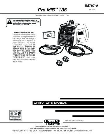
FULL SCALE SOLUTIONThe first commercially available system to integrate all DO-160 waveforms.A system that has grown to meet new and evolving market requirements.WF2, 3 & 6 SystemWF1, 4, 5A & 5B SystemMIG-OS-MB MIG-OS-MB-EXTMIG 0600 MS MIG 0618SS PIN Injection PIN Injection Single Stroke Single Stroke Multiple Stroke Multiple Stroke Multiple BurstCN-MIG-BT3 & CN-MIG-BT5CN-GI-CI & CN-GI-CI-V Cable Bundle Cable Bundle Ground InjectionIncluded Benefits4Reliablekeeps on going during long test phasesPrecisedelivers the same pulse repeatedlyStablea tried and trusted solution used at over 100 locations worldwidePolaritychange polarity by electronic switchingFlexiblemeet many requirements through a big range of accessoriesAutomatedsave and repeat test routines
AVAILABLE CIRCUITSFull scale indirect test system includes all waveforms for RTCA DO-160: Section 22and MIL-STD-461G: CS117 testing. The basic system can be easily extended to meetOEM specific requirements.Waveform 1 (6.4/69μs)MIL-STD-461 / CS117Current Impulse››››Cable Bundle Single StrokeCable Bundle Multiple StrokeWaveform 2 (0.1 and 0.3/6.4μs)RTCA DO-160 / S.22Voltage Impulse››››Cable Bundle Single StrokeCable Bundle Multiple StrokeWaveform 3 (1MHz & 10MHz)RTCA DO-160 / S.22Voltage & Current Impulse››››››››PIN injectionCable Bundle Single StrokeCable Bundle Multiple StrokeCable Bundle Multiple BurstWaveform 4 (6.4/69μs)RTCA DO-160 / S.22Voltage Impulse››››››PIN InjectionGround Injection Single StrokeGround Injection Multiple StrokeWaveform 5A (40/120μs)RTCA DO-160 / S.22Current Impulse››››››PIN InjectionCable Bundle Single StrokeCable Bundle Multiple StrokeWaveform 5B (50/500μs)RTCA DO-160 / S.22Current Impulse››››››PIN InjectionCable Bundle Single StrokeCable Bundle Multiple StrokeWaveform 6 (0.25/4μs)RTCA DO-160 / S.22Current Impulse››Cable Bundle Multiple Burst5
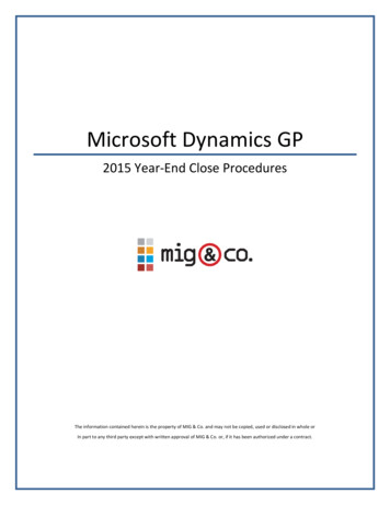
UNIQUE FEATURESTried and trusted technology developed in partnership with industry.Latest generation, solidstate, precise technology.6Easy upgradeSynchronizationAdd functionality without systemdowntime.PIN injection pulses synchronized toAC powerSpecial couplersCustomizable patternsCustomized for specific tests for otheravionic applications.Multiple Stroke & Burst patterns freelyprogrammable in the generator or usingthe pattern upload software.
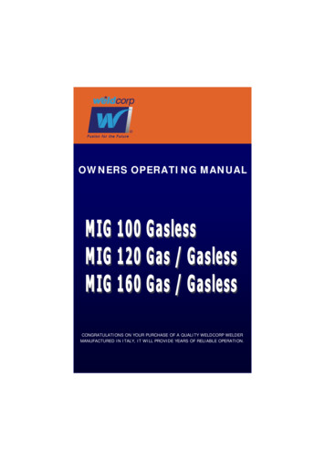
OEM SPECIFIC &SPECIAL APPLICATIONSMany years working with the avionics industry has taught us one thing. Flexibility is the keyto success. EMC PARTNER’s ability to extend and customize the standard system is legendary.Some OEMs require testing with fixed impedance waveforms, even for cable bundle.The EMC PARTNER system is flexible enough to offer this capability with external couplers.Special application requests are nothing new to EMC PARTNER. One example is the solution forlarge diameter cables that can only pass once through a coupler. Applicable for voltage andcurrent waveforms, this unique set of couplers can be used for waveforms 1, 4, 5A and 5B.7
Other systems forindirect lightning DO 160 SECTION 22 LEVEL 3 MIL-STD-461 CS117 INTERNAL EQUIPMENT TEST LEVELS COMPACT SOLUTION BUILT ON EXPERIENCEWWW.EMC-PARTNER.COM/AVI8
Technical Specifications9
DO-160 G SECTION 22 AND MIL-STD-461 G CS117CONFIGURABLE TEST SYSTEM FOR ALL TEST LEVELSTest equipmentDO-160G Section 22MIL-STD-461G CS117Airbus, Boeing, otherGenerators*MIG0600MS MIG0618SS MIG-OS-MB MIG3618SS AccessoriesMIG-OS-MB-EXT NW-WF2-FS NW-WF2-SS NW-WF3-1M-FS NW-WF3-1M-SS NW-WF3-10M-FS NW-WF3-10M-SS NW-WF6H-MB Custom plugins, NWsavailable, send inquiryDN-LISN160-32 SHUNT0E1 V-PROBE-PHV V-PROBE-SI I-PROBE-MB-P1 I-PROBE-MS NW-MS-LEVEL1 optional SYNC-ADAPTER CN-MIG-TT AC-DC-DECOUPLER2 AC-DC-DEC Level 4&5 CDN-BDBC RACK-36HE-MB CN-MIG-BT3 CN-MIG-BT5 CN-GI-CI recommended N-WF5A2000optionaloptionaloptionalCoupling devicesCN-GI-CI-VSoftware10one TEMA license per generator requiredTEMA TEMA EXT-MEASURE OPTICAL LINK * Generators require couplers and accessories as indicated, in order to meet the requirements.
GENERATORS LEVEL 5 AND HIGHER1. MIG0600MSMIG0600MS circuit: WF1 cable inductionStandardsCoupling modeCurrent waveform WF1Test levelTest level single strokeTest level multiple strokeRequiresDO-160G S22, MIL-STD-461G CS117, otherCable Induction (CI)6.4 µs 20 % / 69 µs 20 %specified at coupler output20 A – 1800 A (up to 3200 A can be applied)40 A – 1800 A (first stroke)20 A – 900 A (subsequent stroke)CN-GI-CIMIG0600MS circuit: WF4, pin injectionStandardsCoupling modeOutput impedanceVoltage, current WF4Test levelTest level single strokeSynchronizationDO-160G S22, otherpin injection / direct application5Ω6.4 µs 20 % / 69 µs 20 %specified at application point70 V – 1700 Vautomatic on power peak (SYNC-ADAPTER)MIG0600MS circuit: WF4 cable inductionStandardsCoupling modeVoltage waveform WF4Test levelTest level single strokeTest level multiple strokeRequiresDO-160G S22, MIL-STD-461G CS117, otherCable Induction (CI)6.4 µs 20 % / 69 µs 20 %specified at coupler output25 V – 1600 V25 V – 750 V (first stroke)12.5 V – 190 V (subsequent stroke)CN-GI-CI-VMIG0600MS circuit: WF4 ground injectionStandardsCoupling modeVoltage waveform WF4Test levelTest level single strokeTest level multiple strokeEUT max. powerRequiresDO-160G S22, otherGround Injection (GI)6.4 µs 20 % / 69 µs 20 %specified at application point25 V – 1700 V25 V – 800 V (first stroke)12.5 V – 400 V (subsequent stroke)230 V / 32 A @ 50/60 HzCN-GI-CI-VGenerators Accessories Coupling Devices Software11
MIG0600MS circuit: WF5A, pin injectionStandardsCoupling modeOutput impedanceVoltage, current WF5ATest levelTest level single strokeSynchronizationDO-160G S22, otherpin injection / direct application1Ω40 µs 20 % / 120 µs 20 %specified at application point50 V – 1600 V ( 50 A – 1600 A)automatic on power peakMIG0600MS circuit: WF5A cable inductionStandardsCoupling modeCurrent waveform WF5ATest levelTest level single strokeTest level multiple strokeRequiresDO-160G S22, MIL-STD-461G CS117, otherCable Induction (CI)40 µs 20 % / 120 µs 20 %specified at coupler output60 A – 5000 A60 A – 2000 A (first stroke)30 A – 1000 A (subsequent stroke)CN-GI-CIMIG0600MS circuit: WF5A ground injectionStandardsCoupling modeCurrent waveform WF5ATest levelTest level single strokeTest level multiple strokeEUT max. powerRequiresDO-160G S22, otherGround Injection (GI)40 µs 20 % / 120 µs 20 %specified at application point60 A – 5000 A60 A – 2000 A (first stroke)30 A – 1000 A (subsequent stroke)230 V / 32 A @ 50/60 HzCN-GI-CIMIG0600MS circuit: WF5B, pin injectionStandardsCoupling modeOutput impedanceVoltage, current WF5BTest levelTest level single strokeSynchronizationDO-160G S22, otherpin injection / direct application1Ω50 µs 20 % / 500 µs 20 %specified at application point50 V – 500 V ( 50 A – 500 A)automatic on power peakGenerators Accessories Coupling Devices Software12
MIG0600MS circuit: WF5B cable inductionStandardsCoupling modeCurrent waveform WF5BTest levelTest level single strokeTest level multiple strokeRequiresDO-160G S22, MIL-STD-461G CS117, otherCable Induction (CI)50 µs 20 % / 500 µs 20 %specified at coupler output75 A – 2000 A (up to 5000 A can be applied)30 A – 1800 A (first stroke)30 A – 1000 A (subsequent stroke)CN-GI-CIMIG0600MS circuit: WF5B ground injectionStandardsCoupling modeCurrent waveform WF5BTest levelTest level single strokeTest level multiple strokeEUT max. powerRequiresDO-160G S22, otherGround Injection (GI)50 µs 20 % / 500 µs 20 %specified at application point75 A – 2000 A (up to 5000 A can be applied)30 A – 1800 A (first stroke)30 A – 1000 A (subsequent stroke)230 V / 32 A @ 50/60 HzCN-GI-CIMIG0600MS control featuresUser interfaceCommunication interfacePulse voltage monitor BNCSurge current monitor BNCSurge voltage on displaySurge current on displayTrigger outTrigger inPower synchro. on/off PINLCD and keypad, efficient menu structureRS232 with (optional) adapter to USB10 V 1600 V, accuracy 3% (only PIN)10 V 1600 A, accuracy 3% (only PIN)75 – 1600 V, accuracy 3% (only PIN)25 – 1600 A, accuracy 3%, (only PIN)BNC, max. 12 Vauto, manual, external (BNC input)0 – 360 , 1 steppositive, negative, alternating (electronicImpulse polarityswitch)Impulse repetition s. stroke WF1/WF4: 20 s, WF5A: 20 s, WF5B: 40 sPatternsDO-160, user programmableSpacing multiple stroke10 ms – 500 msMax. number of pulses25 every 20 sImpulse counterprogrammable up to 29’999Programmable rampscurrent or voltage, depending on waveformEmergency stopEmergency Stop button, BNC input, interlockInternal memoryup to 15 tests can be saved and recalledGenerators Accessories Coupling Devices Software13
MIG0600MS supply, weight, dimensions, climatic conditionsOperating voltagePower consumptionWeightWxdxhVersion115 / 230 V (50/60 Hz) 10%ON 400 VA, standby 10 VA295 kg60 x 65 x 184 cm19“ rack, 36 UH with wheels, easy to moveTemperature rangeHumidityAir pressure10 – 35 C 80 % non-condensing86 – 106 kPaIncluded articlesPower cordUser manualCalibration certificatewith country plugwith conformity declarationfactory calibrationMIG0600MS optional accessoriesLISNAdaptersVoltage probeCurrent probeCoupling devices (CI)SoftwareAlternative model 0600SSDN-LISN160-32NW-MS-LEVEL1, SYNC-ADAPTERV-PROBE-SII-PROBE-MSCN-GI-CI, CN-GI-CI-V, otherTEMA, for latest Windows, OPTICAL LINKTEMA-EXT-MEASURE, for DSO controlprice optimised single stroke model available2. MIG0618SSMIG0618SS circuit: WF1 cable inductionStandardsCoupling modeCurrent waveform WF1Test levelTest level single strokeRequiresDO-160G S22, otherCable Induction (CI)6.4 µs 20 % / 69 µs 20 %specified at coupler output250 A – 3500 ACN-GI-CIMIG0618SS circuit: WF4, pin injectionStandardsCoupling modeOutput impedanceVoltage, current WF4DO-160G S22, otherpin injection / direct application5Ω6.4 µs 20 % / 69 µs 20 %Generators Accessories Coupling Devices Software14
Test levelTest level single strokeSynchronizationspecified at application point125 V – 3400 Vautomatic on power peakMIG0618SS circuit: WF4 ground injectionStandardsCoupling modeVoltage waveform WF4Test levelTest level single strokeEUT max. powerRequiresDO-160G S22, otherGround Injection (GI)6.4 µs 20 % / 69 µs 20 %specified at application point125 V – 3400 V230 V / 32 A @ 50/60 HzCN-GI-CI-VMIG0618SS circuit: WF5A, pin injectionStandardsCoupling modeOutput impedanceVoltage, current WF5ATest levelTest level single strokeSynchronizationDO-160G S22, otherpin injection / direct application1Ω40 µs 20 % / 120 µs 20 %specified at application point125 V – 3200 Vautomatic on power peakMIG0618SS circuit: WF5A cable inductionStandardsCoupling modeCurrent waveform WF5ATest levelTest level single strokeRequiresDO-160G S22, MIL-STD-461G CS117, otherCable Induction (CI)40 µs 20 % / 120 µs 20 %specified at coupler output400 A – 6000 A (up to 10000 A can be applied)CN-GI-CIMIG0618SS circuit: WF5A ground injectionStandardsCoupling modeCurrent waveform WF5ATest levelTest level single strokeEUT max. powerRequiresDO-160G S22, otherGround Injection (GI)40 µs 20 % / 120 µs 20 %specified at application point400 A – 6000 A230 V / 32 A @ 50/60 HzCN-GI-CIGenerators Accessories Coupling Devices Software15
MIG0618SS control featuresUser interfaceCommunication interfacePulse voltage monitor BNCSurge current monitor BNCSurge voltage on displaySurge current on displayTrigger outTrigger inPower synchro. on/off PINLCD and keypad, efficient menu structureRS232 with (optional) adapter to USB10 V 6000 V, accuracy 3% (only PIN)10 V 6000 A, accuracy 3% (only PIN)75 – 6000 V, accuracy 3% (only PIN)25 – 6000 A, accuracy 3%, (only PIN)BNC, max. 12 Vauto, manual, external (BNC input)0 – 360 , 1 steppositive, negative, alternating (electronicImpulse polarityswitch)Impulse repetition s. stroke starting with 4 sImpulse counterprogrammable up to 29’999Programmable rampscurrent or voltage, depending on waveformEmergency stopEmergency Stop button, BNC input, interlockInternal memoryup to 15 tests can be saved and recalledMIG0618SS supply, weight, dimensions, climatic conditionsOperating voltagePower consumption115 / 230 V (50/60 Hz) 10%ON 400 VA, standby 10 VAWeightWxdxhVersion170 kg60 x 65 x 123 cm19“ rack, 18 UH with wheels, easy to moveTemperature rangeHumidityAir pressure10 – 35 C 80 % non-condensing86 – 106 kPaIncluded articlesPower cordUser manualCalibration certificatewith country plugwith conformity declarationfactory calibrationMIG0618SS optional accessoriesLISNAdaptersVoltage probeCurrent probeCoupling devices (CI)SoftwareDN-LISN160-32NW-MS-LEVEL1, SYNC-ADAPTERV-PROBE-SII-PROBE-MSCN-GI-CI, CN-GI-CI-V, otherTEMA, for latest Windows, OPTICAL LINKTEMA-EXT-MEASURE, for DSO controlGenerators Accessories Coupling Devices Software16
3. MIG-OS-MBMIG-OS-MB circuit: WF2 cable inductionStandardsCoupling modeVoltage waveform WF2Test levelTest level single strokeTest level multiple strokeRequiresDO-160G S22, MIL-STD-461G CS117, otherCable Induction (CI)rise time: 100 ns ( or/and 340 ns)pulse duration: 6.4 µs 20 %specified at coupler output40 V – 1700 V25 V – 1600 V (first stroke)12.5 V – 800 V (subsequent stroke)CN-MIG-BT3MIG-OS-MB circuit: WF3, 1 MHz, pin injectionStandardsCoupling modeOutput impedanceVoltage, current WF3Test levelTest level single strokeSynchronizationEUT max. powerDO-160G S22, otherpin injection / direct application25 Ωfrequency: 1 MHz 20 %damping: 25 – 75 % (1st to 5th peak)specified at application point80 V – 600 V0 – 360 , step 1 230 V / 400 Hz, 115 V / 800 HzMIG-OS-MB circuit: WF3, 1 MHz, cable inductionStandardsCoupling modeVoltage, current WF3Test levelTest level single strokeTest level multiple strokeTest level multiple burstRequiresDO-160G S22, MIL-STD-461G CS117, otherCable Induction (CI)frequency: 1 MHz 20 %damping: 25 – 75 % (1st to 5th peak)specified at coupler output80 V – 1500 V80 V – 600 V (first stroke)80 V – 600 V (subsequent stroke)60 V – 900 VCN-MIG-BT5Generators Accessories Coupling Devices Software17
MIG-OS-MB circuit: WF3, 10 MHz, cable inductionStandardsCoupling modeVoltage, current WF3Test levelTest level single strokeTest level multiple strokeTest level multiple burstSynchronizationRequiresDO-160G S22, MIL-STD-461G CS117, otherCable Induction (CI)frequency: 10 MHz 20 %damping: 25 – 75 % (1st to 5th peak)specified at coupler output80 V – 1500 V80 V – 1500 V (first stroke)80 V – 1500 V (subsequent stroke), adjustable50 V – 1920 V0 – 360 , step 1 CN-MIG-BT5MIG-OS-MB control featuresUser interfaceCommunication interfacePulse voltage monitor BNCSurge current monitor BNCSurge voltage on displaySurge current on displayTrigger outTrigger inPower synchro. on/off PINLCD and keypad, efficient menu structureRS232 with (optional) adapter to USB10 V 6000 V, accuracy 3% (only PIN)10 V 6000 A, accuracy 3% (only PIN)75 – 6000 V, accuracy 3% (only PIN)25 – 6000 A, accuracy 3%, (only PIN)BNC, max. 12 Vauto, manual, external (BNC input)0 – 360 , 1 steppositive, negative, alternating (electronicImpulse polarityswitch)Impulse repetition s. stroke starting with 0.1 sImpulse counterprogrammable up to 29’999Programmable rampscurrent or voltage, depending on waveformEmergency stopEmergency Stop button, BNC input, interlockInternal memoryup to 15 tests can be saved and recalledMIG-OS-MB supply, weight, dimensions, climatic conditionsOperating voltagePower consumption115 or 230 V (50/60 Hz) 10%ON 400 VA, standby 10 VAWeightWxdxhVersion40 kg45 x 57 x 37 cm19“ unit, 8 UHTemperature rangeHumidityAir pressure10 – 35 C 80 % non-condensing86 – 106 kPaIncluded articlesPower cordUser manualCalibration certificatewith country plugwith conformity declarationfactory calibrationGenerators Accessories Coupling Devices Software18
MIG-OS-MB optional accessoriesPlugins for higher test levels MIG-OS-MB-EXT, NW-WF2-FS, NW-WF2-SS,NW-WF3-1M-FS, NW-WF3-1M-SS,NW-WF3-10M-FS, NW-WF3-10M-SS,NW-WF6H-MB, custom pluginsLISNDN-LISN160-32Adapters / decouplersCN-MIG-TT, AC-DC-DECOUPLER2,AC-DC-DECOUPLER 4&5, CN-BDBCVoltage probeV-PROBE-PHVCurrent probeI-PROBE-MB-P1Coupling devices (CI)CN-MIG-BT3, CN-MIG-BT5SoftwareTEMA, for latest Windows, OPTICAL LINKTEMA-EXT-MEASURE, for DSO control4. MIG3618SSMIG3618SS circuit: WF 6.4/69 µsStandardOutput impedanceVoltage waveformTest levelCurrent max.SAE ARP5416A, paragraph 6.1.6: 20131 to 2 Ω6.4 µs 20 % / 69 µs 20 %3000 V – 36000 Vfor example: 2500 A in load 20 µH / 5 Ωfor example: 5000 A in load 20 µH / 0.1 ΩMIG3618SS control featuresUser interfaceCommunication interfaceSurge current monitor BNCSurge current on displayTrigger inLCD and keypad, efficient menu structureRS232 with (optional) adapter to USB10 V 6000 A, accuracy 3%25 – 6000 A, accuracy 3%auto, manual, external (BNC input)positive, negative, alternating (electronicImpulse polarityswitch)Impulse repetition s. stroke 1 / 12 s @ 3 kV, 1 / 60 s @ 36 kVImpulse counterprogrammable up to 29’999Programmable rampsvoltageEmergency stopEmergency Stop button, BNC input, interlockInternal memoryup to 15 tests can be saved and recalledGenerators Accessories Coupling Devices Software19
MIG3618SS supply, weight, dimensions, climatic conditionsOperating voltagePower consumption115 / 230 V (50/60 Hz) 10%ON 400 VA, standby 10 VAUnit 1 (generator rack)WeightWxdxhVersion200 kg61 x 68 x 102 cm19“ rack, 18 4 UH, on wheels, easy to moveUnit 2 (controller)WeightWxdxhVersion31 kg45 x 60 x 19 cm19“ unit / table top unit, 4 UHTemperature rangeHumidityAir pressure10 – 35 C 80 % non-condensing86 – 106 kPaIncluded articlesPower cordUser manualCalibration certificatewith country plugwith conformity declarationfactory calibrationMIG3618SS optional accessoriesCustom Rs, Ls, RpSoftwareon demandTEMA, for latest Windows, OPTICAL LINKTEMA-EXT-MEASURE, for DSO controlGenerators Accessories Coupling Devices Software20
ACCESSORIESMIG-OS-MB-EXTApplicationTest level WF2Test level WF3 1 MHzTest level WF3 10 MHzTest level WF6WeightDimensionsSupplyFor generatorRequiresRequiresextends MIG-OS-MB to L5 test levelsrequires necessary plugin(s) for each WFextended up toextended up toextended up to5 A – 160 A (multiple burst)18 kg (empty)19” unit, 4 UHnormal mains 230 V or 115 V, fusedMIG-OS-MBplugins for necessary waveforms:NW-WF2-FS, NW-WF2-SS,NW-WF3-1M-FS, NW-WF3-1M-SS,NW-WF3-10M-FS, NW-WF3-10M-SS,NW-WF6H-MB, custom pluginsRACK-36HE-MBNW-WF2-FSApplicationTest level WF2 first strokeWeightDimensionsFor generatorRequiresWF2 First Stroke (FS) plugin,extends MIG-OS-MB to L5 extended up to 4500 V3 kg17 x 22 x 18 cmMIG-OS-MBMIG-OS-MB-EXTNW-WF2-SSApplicationTest level WF2 sub. strokeWeightDimensionsFor generatorRequiresWF2 Subsequent Stroke (FS) plugin,extends MIG-OS-MB to L5 extended up to 1100 V2 kg17 x 22 x 18 cmMIG-OS-MBMIG-OS-MB-EXT, NW-WF2-FSNW-WF3-1M-FSApplicationTest level WF3 first strokeWeightDimensionsFor generatorRequiresWF3 1 MHz First Stroke (FS) plugin,extends MIG-OS-MB to L5 extended up to 5000 V (1 MHz)2 kg17 x 22 x 18 cmMIG-OS-MBMIG-OS-MB-EXTGenerators Accessories Coupling Devices Software21
NW-WF3-1M-SSApplicationTest level WF3 sub. strokeWeightDimensionsFor generatorRequiresWF3 1 MHz Subsequent Stroke (FS) plugin,extends MIG-OS-MB to L5 extended up to 2250 V (1 MHz)2 kg17 x 22 x 18 cmMIG-OS-MBMIG-OS-MB-EXT, NW-WF3-1M-FSNW-WF3-10M-FSApplicationTest level WF3 first strokeWeightDimensionsFor generatorRequiresWF3 1 MHz First Stroke (FS) plugin,extends MIG-OS-MB to L5 extended up to max. 3400 V (10 MHz)2 kg17 x 22 x 18 st level WF3 sub. strokeWeightDimensionsFor generatorRequiresWF3 10 MHz Subsequent Stroke(FS) plugin,extends MIG-OS-MB to L5 extended up to max. 1900 V (10 MHz)2 kg17 x 22 x 18 cmMIG-OS-MBMIG-OS-MB-EXT, NW-WF3-10M-FSNW-WF6H-MBApplicationTest level WF6 MBWeightDimensionsFor generatorRequiresWF6 multiple burst (MB) plugin,extends MIG-OS-MB with WF6 capability5 A – 180 A2.2 kg17 x 22 x 18 cmMIG-OS-MBMIG-OS-MB-EXTCUSTOM PLUGINApplicationFor generatorRequiresContactdifferent plugins available on requestextends MIG-OS-MB with more r.chDN-LISN160-32StandardsApplicationDO-160G S22, MIL-STD-461G CS117, otherLine Impedance Stabilization Network (5 µH)Generators Accessories Coupling Devices Software22
InductanceCapacitanceNumber of linesAC voltage max.AC current max.DC voltage max.DC current max.WeightDimensionsFor generatorsRequirements5 µH per line (for both AC and DC lines)10 µF included, 33000 µF includedLISN is calibrated with capacitors connected2 AC lines (L, N or L1, L2), 2 DC lines ( / -)L-N: 480 V @50/60 Hz, L-PE: 280 V @50/60 HzL-N: 150 V @ 400 Hz, L-PE: 85 V @ 400 Hz32 A50 V32 A13 kg45 x 57 x 19 cm, 19’’ unit, 4 UHAVI3000,MIG0600MS,MIG0618 SS,MIG-OS-MBfor 3-phase EUTs, two pieces are nsRequirescalibration of WF2, WF3 short circuit current0.1 Ω 2 %0.15 kg12 x 2.5 x 2.5 cmMIG-OS-MB, CN-MIG-BT3 or CN-MIG-BT5V-PROBE-PHVStandardsType of probeInput voltageBandwidth (-3 dB)Usable rise timeAccuracyAttenuation ratioInput impedanceCompensation rangeDSO input selectionWeightDimensionsIncludedDO-160G S22, MIL-STD-461G CS117, othercommon mode / passivemax. 1 kV r.m.s., max. 4 kV impulse250 MHz1.4 ns 2%100:150 MΩ 7.5 pF10 – 50 pF1 MΩ0.5 kg24 x 28 x 9 cm (packed)carrying caseGenerators Accessories Coupling Devices Software23
V-PROBE-SIStandardsType of probeInput voltageBandwidthAccuracyInput impedanceAttenuation ratioPower supplyWeightDimensionsIncludedDO-160G S22, MIL-STD-461G CS117, otherdifferential (can measure CM as well)max. 7 kV DC peak, max. 2.5 kV r.m.s.DC – 70 MHz (-3 dB) 2%10 MΩ 10 pF1:100 or 1:10004 x AA batteries and/or mains adapter1.5 kg (packed)29 x 34 x 8 cm (packed)carrying case, mains adapter, AA batteriesI-PROBE-MB-P1StandardsApplicationOutput impedanceInput currentWaveformsBandwidth (-3 dB)SensitivityAccuracyCurrent time productI/fUsable rise timeDSO input selectionWeightDimensionsIncludedDO-160G S22, MIL-STD-461G CS117, othermeasurement of SC current / clamp on probe50 Ω (BNC connector)max. 100 A r.m.s., max. 5 kA impulseWF2, WF3 (1&10 MHz), WF6, other5 Hz – 15 MHz0.1 V/A into 1 MΩ 1/-0%0.5 As3.5 A/Hz25 ns1 MΩ1.68 kg12 x 13 x 4 cm (inner diameter 5 cm)carrying caseI-PROBE-MSStandardsApplicationOutput impedanceInput currentWaveformsBandwidth (-3 dB)SensitivityAccuracyCurrent time productI/fUsable rise timeDSO input selectionWeightDimensionsFor generatorsIncludedDO-160G S22, MIL-STD-461G CS117, othermeasurement of SC current / clamp on probe50 Ω (BNC connector)max. 12 kA impulseWF1, WF4 (SC), WF5A, WF5B, other1 Hz – 16 MHz0.5 mV/A into 1 MΩ 1%0.5 As3.5 A/Hz25 ns1 MΩ1.5 kg28 x 24 x 9 cm packed (inner diameter 9 cm)MIG0600MS, MIG0618SScarrying case, 4 x 1.5 V AA batteriesGenerators Accessories Coupling Devices Software24
NW-MS-LEVEL1StandardsApplicationLowest test level WF4 PINLowest test level WF5A PINLowest test level WF5B PINCan be used also forWeightDimensionsFor generatorDO-160G S22, MIL-STD-461G CS117, otherallows lower test levels to be applied to EUT50 V ensured50 V ensured50 V ensuredWF1, WF4, WF5A, WF5B cable bundle tests2 kg8 x 24 x 9 cmMIG0600MSSYNC-ADAPTERStandardsApplicationFor generatorDO-160G S22, otherallows sync. on EUT power, PIN 160G S22 (pin injection), otherTest tip for PIN injectionAC-DC-DECOUPLER2StandardsApplicationTest level WF2 max.Test level WF3 max.EUT supply voltage max.WeightDimensionsFor generatorRemarkDO-160G S22 (pin injection), otherdecoupling network for powered pins3200 V4000 V230 V (50 – 400 Hz), 115 V (800 Hz), 230 V DC0.2 kg2.5 x 12.5 x 2.5 cmMIG-OS-MBfor higher test levels useAC-DC-DEC 4&5StandardsApplicationTest level WF2 max.DO-160G S22 (pin injection), otherdecoupling network for powered pins3200 VEUT supply voltage max.WeightDimensionsFor generatorRemark230 V (50 – 400 Hz), 115 V (800 Hz), 230 V DC0.2 kg2.5 x 16 x 2.5 cmMIG-OS-MB-EXT and WF2, WF3 pluginsrecommended for levels 4 and 5Test level WF3 max.6000 VGenerators Accessories Coupling Devices Software25
CDN-BDBCStandardsApplicationFor waveformsWeightDimensionsDelivery containsFor generatorsDO-160G S22 (pin injection), otherblocking devices and bypass circuitry for pin inj.WF4 (WF1), WF5A up to 1600 V / 3200 A0.3 kg (packed)14 x 17 x 5 cm (packed)two bypass/blocking devicesMIG0600MS, MIG0618SS (pin ptional rack with wheels for MIG-OS-MB,MIG-OS-MB-EXT and storage for 6 plugins142 kg (includes generator, extension, plugins)60 x 65 x 180 cm (19” rack / 36 UH)Generators Accessories Coupling Devices Software26
COUPLING sionsWeightFor generatorIncludedRequiresDO-160G S22, MIL-STD-461G CS117, otherinjection probe for cable bundle testsWF2 levels 1 - 5WF3 levels 4-5WF 6 levels 1 - 57.7 x 7.7 cm21 x 45 x 19 cm34 kgMIG-OS-MB with extension and pluginscalibration loop, HV connection cableSHUNT0E1 for short circuit imensionsWeightFor generatorIncludedRequiresDO-160G S22, MIL-STD-461G CS117, otherinjection probe for WF3 levels 1-38 x 7 cm22 x 22 x 20 cm13 kgMIG-OS-MBcalibration loop, HV connection cableSHUNT0E1 for short circuit calibrationCN-GI-CIStandardsApplicationTest levelsEUT supplyApertureEUT cable turnsDimensionsWeightFor generatorsIncludedDO-160G S22, MIL-STD-461G CS117, otherinjection probe for:WF1, WF5A, WF5B in cable induction mode,WF4, WF5A, WF5B in ground injection mode1 – 5 for mentioned waveforms230 V / 32 A 50/60 Hz, 10 A 400/800 Hz4 x 4 cmone complete turn is enough45 x 60 x 27 cm53 kgMIG0600MS, MIG0618SSconnection cablesGenerators Accessories Coupling Devices Software27
CN-GI-CI-VStandardsApplicationTest level WF4EUT supplyApertureDimensionsWeightFor generatorsIncludedMIL-STD-461G CS117, DO-160G S22, otherinjection probe for WF4, WF5A (voltage) incable induction mode50 – 1600 V230 V / 32 A 50/60 Hz, 10 A 400/800 Hz6 x 12 cm53 x 65 x 50 cm190 kgMIG0600MS, MIG0618SSconnection cablesCN-CI-I1StandardsApplicationTest levelsEUT supplyApertureEUT cable turnsDimensionsWeightFor generatorsIncludedDO-160G S22, MIL-STD-461G CS117, otherlarge aperture coupler for WF1, WF5A, WF5B,cable induction mode (current waveforms)ask for details230 V / 32 A 50/60 Hz, 10 A 400/800 Hz6 x 15 cmcable straight through coupler45 x 60 x 38 cm160 kgMIG0600MSconnection cablesCN-CI-V1StandardsApplicationTest levelsEUT supplyApertureEUT cable turnsDimensionsWeightFor generatorsIncludedDO-160G S22, MIL-STD-461G CS117, otherlarge aperture coupler for WF4, WF5A, WF5B,cable induction mode (voltage waveforms)ask for details230 V / 32 A 50/60 Hz, 10 A 400/800 Hz6 x 15 cmcable straight through coupler51 x 95 x 36 cm292 kgMIG0600MSconnection cablesCN-WF5A1500StandardsApplicationOutput impedanceTest level WF5A (CI)EUT supplyAirbus ABD0100.1.2 G, Boeingcoupler for WF5A with 1 Ω impedance1Ωup to 1500 V / 1500 A230 V / 32 A 50/60 Hz, 10 A 400/800 HzGenerators Accessories Coupling Devices Software28
ApertureDimensionsWeightFor generatorsIncluded6 x 15 cm65 x 130 x 110 cm525 kg including hydraulic positioning cartMIG0600MSconnection cables, hydraulic cart, control boxCN-WF5A2000StandardsApplicationOutput impedanceTest level WF5A (CI)EUT supplyApertureDimensionsWeightFor generatorsIncludedAirbus ABD0100.1.2 G, Boeingcoupler for WF5A with 1 Ω impedance1Ωup to 2000 V / 2000 A230 V / 32 A 50/60 Hz, 10 A 400/800 Hz6 x 15 cm65 x 130 x 110 cm645 kg including hydraulic positioning cartMIG0600MSconnection cables, hydraulic cart, control boxSOFTWARETEMASuitable for generatorsIncludesSeparate licenseOperating system requiredCommunication portUpdatesLatest versionOptionalMIG0600MS, MIG0618SS, MIG-OS-MBremote control of generator, automatic testreport, sequence modeDSO control requires TEMA EXT-MEASUREWindows, latestUSBlifetime updates at no additional costavailable on EMC PARTNER website10m OPTICAL-LINK fibre for remote control29
THE EMC PARTNER PRODUCT RANGEFind further brochures on our website emc-partner.com/brochures orcontact your local representative for a hardcopy.IMMUNITY TESTSTransient Test Systems for all EMC tests on electronic equipment. ESD,EFT, surge, AC dips, AC magnetic field, surge magnetic field, commonmode, damped oscillatory and DC dips. According to IEC and EN 610004-2, -4, -5, -8, -9, -10, -11, -12, -13, -14, -16, -18, -19, -29.LIGHTNING TESTSImpulse test equipment and accessories for aircraft, military and telecom applications. Complete solutions for RTCA / DO-160 an
RTCA DO-160 / S.22 RTCA DO-160 / S.22 RTCA DO-160 / S.22 RTCA DO-160 / S.22 RTCA DO-160 / S.22 RTCA DO-160 / S.22 5. UNIQUE FEATURES Tried and trusted technology developed in partnership with industry.Latest generation, solid . Test equipment DO-160G Section 22 MIL-STD-461G CS117 Airbus, Boeing, other