Transcription
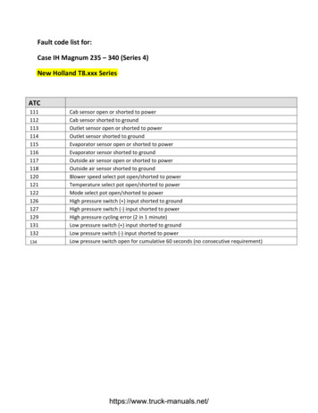
Fault code list for:Case IH Magnum 235 – 340 (Series 4)New Holland T8.xxx 9131132134Cab sensor open or shorted to powerCab sensor shorted to groundOutlet sensor open or shorted to powerOutlet sensor shorted to groundEvaporator sensor open or shorted to powerEvaporator sensor shorted to groundOutside air sensor open or shorted to powerOutside air sensor shorted to groundBlower speed select pot open/shorted to powerTemperature select pot open/shorted to powerMode select pot open/shorted to powerHigh pressure switch ( ) input shorted to groundHigh pressure switch (‐) input shorted to powerHigh pressure cycling error (2 in 1 minute)Low pressure switch ( ) input shorted to groundLow pressure switch (‐) input shorted to powerLow pressure switch open for cumulative 60 seconds (no consecutive requirement)https://www.truck-manuals.net/
710281029103010311032103310341035103610371065Raise hitch valve coil short to 12 volts or raise hitch valve coil circuit failure.Open or Short to Ground raise hitch valve coil circuit failure.Lower hitch valve coil short to 12 volts or lower hitch valve coil circuit failure.Open or short to ground lower hitch valve coils.EDC Low Side Driver stuck on failure.Low side driver watchdog test failed.Low side of raise solenoid connected permanently to GNDLow side of lower solenoid connected permanently to GNDTCU (Tractor Controller Unit) is disconnected from the CAN bus.No communication with the ACM (Armrest Controller Module).No communication with the ICP (Instrument Cluster Panel).Five‐volt reference is above the upper voltage limit.Five‐volt reference is below the lower voltage limit.Not implementedPosition Command value received over the CAN data bus from the Armrest indicates PositionCommand potentiometer failed.Hitch rockshaft position potentiometer open/short/misadjust or circuit failure.Upper Limit value received from CAN data bus indicates failure condition.Load Command value received from CAN data bus indicates failure condition.Single draft pin sensor failed when configured for one draft pin sensor.(CCH Only)Two draft pin sensors failed when configured for two draft pins.(CCH Only)ICU CAN data bus signal lost.Up/Down/Down Momentary switch value received from CAN data bus indicates switch failure.Up/Down remote fender switch failure.Not implementedTravel Range potentiometer value received from CAN data bus indicates failure condition.Drop Rate value received from CAN data bus indicates potentiometer failure condition.Right draft pin voltage is outside the normal operating range.(CCH Only)Left draft pin voltage is outside the normal operating range.(CCH Only)Ground speed failure‐value received from CAN data bus indicates failure condition.Slip Limit Set Point received from CAN data bus indicates failure condition.Slip Enable switch received from CAN data bus indicates failure condition.The Percent slip received from ETC indicates failure condition.The ARU reports EDC Inching Up switch faulty or not available.The ARU reports EDC Inching Down switch faulty or not available.The ARU specified tractor without draft control (position only hitch) but detected presence ofdraft pin(s).https://www.truck-manuals.net/
01100110111021103110411051106Engine RPM is too low for lower hitch calibration.The specified tractor has draft control but no draft pin(s) were detected.EDC calibration aborted due to tractor moving during EDC calibration.EDC calibration aborted due to low engine RPM.PWM raise threshold is too high.PWM raise threshold is too low.Not implementedHitch pot signal is not within the expected range for maximum hitch position.PWM lower threshold is too high.PWM lower threshold is too low.Operator did not respond to EDC calibration procedure.Hitch position is not at minimum.Hitch position range is not within limits.Hitch position range to position command range ratio is not within limits.Right draft pin offset voltage is outside the expected voltage range.(CCH Only)Left draft pin offset voltage is outside the expected voltage range.(CCH Only)Left and right draft pin offset voltage is outside the expected voltage range.(CCH Only)EDC is configured with one draft pin but connected to the left side. (CCH Only)EDC require calibration.No communication with the PMU controller.8 volt reference is above 8.8 volts8 volt reference is below 7.2 volts12VH1 voltage supply to the hitch raise and lower coils is low. (possible blown fuse*)Not implementedEDC Top Link switch stuck on fault.(CCH Only)EDC Top Link switch input conflict fault.(CCH Only)EDC Side (Lift) Link switch stuck on fault.(CCH Only)EDC Side Link switch input conflict fault.(CCH Only)12VU1 voltage supply to the EDC Lift Link raise and lower coils is low. (possible blownfuse*)(CCH Only)12VU2 voltage supply to the EDC Top/Side Link load compensation is low. (possible blownfuse*)(CCH Only)12VH1 voltage supply to the EDC Top/Side Link load compensation is low. (possible blownfuse*)(CCH Only)https://www.truck-manuals.net/
6232723302331234223432344234523462374Seat switch open circuitSeat switch is shorted to the supply voltage B or 5 volt referenceClutch Pot Open Circuit or short to groundClutch Potentiometer Short to 12 Volts or short to 5 Volt reference.none of the Transmission clutches are calibrated. This will be the condition when a newcontroller is installed on the tractor.Bottom of Clutch pedal switch open circuit or bottom of clutch relay is stuck openClutch pedal bottom of clutch switch misadjusted.Bottom of Clutch pedal switch or the bottom of clutch relay are short circuit5 volt reference voltage too high.5 volt reference voltage too low.No signal from wheel speed sensor.5 volt internal reference voltage too high.5 volt internal reference voltage too low.1) Switch inputs indicate shuttle lever is in both forward and neutral2) Switch inputs indicateshuttle lever is in both reverse and neutral3) Switch inputs indicate shuttle lever is in bothforward and reverse. Cycle the shuttle lever which may free up stuck switches, or try drivingthe opposite direction.Forward switch input from the FNRP Pod is shorted to 12 Volts or the FNRP pod 5 VoltReference.Forward switch input from the FNRP Pod is shorted to ground or is open circuit.Reverse switch input from the FNRP Pod is shorted to 12 Volts or the FNRP pod 5 VoltReference.Reverse switch input from the FNRP Pod is shorted to ground or open circuit.FNR Not Park Switch low voltage faultFNR Not Park Switch high Voltage faultFNR Neutral Switch Low Voltage faultFNR Neutral Switch high Voltage faultThe Engine RPM sourced from the alternator measured by the controller is excessively high.No engine RPMThe Transmission output RPM speed, sourced from the sensor, measured by the controller istoo high for the desired gearThe transmission clutches are slippingClutch Odd solenoid open circuit or short to ground.Clutch Even solenoid open circuit or short to ground.C33Clutch C1‐2 solenoid open circuit or short to ground.Clutch C3‐4 solenoid open circuit or short to ground.Clutch 5‐6 solenoid open circuit or short to ground.Master Clutch solenoid open circuit or short to ground.https://www.truck-manuals.net/
815281628172818Clutch Low Range solenoid open circuit or short to ground.110 Clutch Mid Range solenoid open circuit or short to ground.Clutch High Range solenoid open circuit or short to ground.Clutch reverse solenoid open circuit or short to ground.The creeper clutch solenoid is open circuit or short to groundEven Clutch Solenoid is shorted to 12 Volts, current sensed while driver is off.Odd Clutch Solenoid is shorted to 12 Volts, current sensed while driver is off.C1‐2 Clutch Solenoid is shorted to 12 Volts, current sensed while driver is off.C3‐4 Clutch Solenoid is shorted to 12 Volts, Current sensed while driver is off.C5‐6 clutch Solenoid is shorted to 12 Volts, current sensed while driver isoff.Low clutch Solenoid is shorted to 12 Volts, current sensed while driver is off.Mid Clutch Solenoid is shorted to 12 Volts, Current sensed while driver is off.High Clutch Solenoid is shorted to 12 Volts, current sensed while driver is off.Reverse Clutch Solenoid is shorted to 12 Volts, current sensed while driver is off.The creeper clutch solenoid is shorted to 12 Volts, current sensed while the driver is offMaster Clutch Solenoid is shorted to 12 Volts, current sensed while driver is off.The Odd Clutch is not calibratedEven Clutch not calibratedC1‐2 Clutch not calibratedC3‐4 Clutch not calibratedC5‐6 Clutch not calibratedLow Range Clutch not calibratedMid Range Clutch not calibratedHigh Clutch not calibratedReverse Clutch not calibratedCreep Clutch is not calibratedMaster Clutch not calibratedAuto Guidance Isolation valve driver FaultSystem pressure valve solenoid circuit is open circuit or shorted to groundSystem pressure solenoid is shorted to B Transmission output rpm over speedThe battery voltage is too low to permit operation of the clutch solenoids.Transmission Oil Temperature HotTransmission Oil Temperature sensor short to B or open circuitTransmission oil temperature Sensor Short to GroundIntegrated Control Panel off lineGovernor Engine RPM alternator engine RPM mismatchTransmission regulated pressure accumulator is flatGovernor is offline CAN busCommunication lost with the Armrest Control Module(ACM)https://www.truck-manuals.net/
9022903291029112912291329142915Communication lost with the instrumentation controller.System pressure low possible System pressure hydraulic pump failure or leakSystem Pressure Low faultThe Park Brake is stuck on by no electrical power supplied when commanded onThe Park Brake Driver has detected an over current or an open circuit conditionThe Park Brake is stuck on by no electrical power supplied to the solenoid when driver iscommanded on. Possible service brake bottom brake switches open.No signal from wheel speed sensor.Software is out of the calibration mode and the park brake request is still active. If this fault isdetected there is a bug in the softwareThe park brakes commanded on and gear is engaged and there is no park brake request fromcalibration. If this fault is detected there is a bug in the softwareTorque sensor Gap is on the larger end of the tolerance (CCH Only)Signal received from the torque sensor is not in any fault range or normal range tolerance (CCHOnly)Torque sensor has declared an internal fault tolerance (CCH Only)Torque sensor supply voltage below 4.8 volts tolerance (CCH Only)12VF1voltage supply is low. (possible blown fuse*)12VT1voltage supply is low. (possible blown fuse*)12VF2voltage supply is low. (possible blown fuse*)12VHvoltage supply is low. (possible blown fuse*)12VF3voltage supply is low. (possible blown fuse*)12VS1voltage supply is low. (possible blown fuse*)https://www.truck-manuals.net/
Engine3000 known ECM Error Code ReceivedFoot Throttle Sensor ‐Signal Not PlausibleFoot Throttle Sensor ‐Signal Above Range Max.Foot Throttle Sensor ‐Signal Below Range Min.Foot Throttle Sensor ‐No Signal ‐ErrorCoolant Temperature Sensor ‐Signal Not Plausible(Compared with Engine Oil Temperature)Coolant Temperature Sensor ‐Signal Above Range Max.Coolant Temperature Sensor ‐Signal Below Range Min.Coolant Temperature Sensor ‐(via CAN) No SignalAir Intake Temperature Sensor ‐Signal Above Range Max.Air Intake Temperature Sensor ‐Signal Above Range Min.Air Intake Temperature Sensor ‐(via CAN) No SignalFuel Temperature Signal ‐Signal Above Range Max.Fuel Temperature Signal ‐Signal Below Range Min.Boost Pressure Sensor ‐Signal Above Range Max.Boost Pressure Sensor ‐(via CAN) No SignalBoost Pressure Sensor ‐Signal Not PlausibleAtmospheric Pressure Sensor ‐Signal Not Plausible Compared with Boost PressureAtmospheric Pressure Sensor ‐Signal Above Range Max.Atmospheric Pressure Sensor ‐Signal Below Range Min.Oil Pressure Too LowOil Pressure Sensor –Short circuit to BatteryOil Pressure Sensor –Short circuit to GroundOil Pressure Sensor ‐Hardware ErrorOil Pressure Sensor ‐Value Too HighOil Temperature Sensor ‐Signal Not Plausible (Compared with Coolant Temperature)Oil Temperature Sensor ‐Signal Above Range Max.Oil Temperature Sensor ‐Signal Below Range Min.Oil Temperature Sensor ‐(via CAN) No SignalBoost Pressure Sensor ‐Signal LowConstant Engine RPM Activate / Select Switch –Short circuit to GroundCruise Control Actuating Device ‐Evaluation ErrorVehicle Speed Sensing ‐Hardware Conversion ErrorVehicle Speed Sensing ‐Signal Above Range Max.Vehicle Speed Sensing ‐Signal Below Range Min.Vehicle Speed Sensing ‐Signal Not Plausiblehttps://www.truck-manuals.net/
3089309030913092Main Relay 2 Failure –Short circuit to BatteryMain Relay 2 Failure –Short circuit to GroundBattery Voltage to ECM too HighBattery Voltage to ECM too LowVehicle Speed Sensing (Tacho) ‐PWM Frequency Too HighVehicle Speed Sensing (Tacho) ‐PWM Average Frequency Above LimitVehicle Speed Sensing (Tacho) ‐PWM Average Frequency Below LimitVehicle Speed Sensing (Tacho) ‐Not PlausibleTimeout of CAN Message High Resolution Wheel SpeedTimeout of CAN Message Vehicle Dynamics Control UnitECM After run was InterruptedCylinder1 ‐Unclassifiable Error in InjectorCylinder1 ‐Injector Cable Short circuit (Low Side to Battery)Cylinder1 ‐Application DependentCylinder1 ‐Injector Cable Short circuit (High Side to Ground)Cylinder5 ‐Unclassifiable Error in InjectorCylinder5 ‐Injector Cable Short circuit (Low Side to Battery)Cylinder5 ‐Application DependentCylinder5 ‐Injector Cable Short circuit (High Side to Ground)Cylinder3 ‐Unclassifiable Error in InjectorCylinder3 ‐Injector Cable Short circuit (Low Side to Battery)Cylinder3 ‐Application DependentCylinder3 ‐Injector Cable Short circuit (High Side to Ground)Cylinder6 ‐Unclassifiable Error in InjectorCylinder6 ‐Injector Cable Short circuit (Low Side to Battery)Cylinder6 ‐Application DependentCylinder6 ‐Injector Cable Short circuit (High Side to Ground)Cylinder2 ‐Unclassifiable Error in InjectorCylinder2 ‐Injector Cable Short circuit (Low Side to Battery)Cylinder2 ‐Application DependentCylinder2 ‐Injector Cable Short circuit (High Side to Ground)Cylinder4 ‐Unclassifiable Error in InjectorCylinder4 ‐Injector Cable Short circuit (Low Side to Battery)Cylinder4 ‐Application DependentCylinder4 ‐Injector Cable Short circuit (High Side to Ground)Crankshaft Sensor ‐No SignalCrankshaft Sensor ‐Invalid SignalCamshaft Sensor ‐No SignalCamshaft Sensor ‐Invalid SignalOffset Between Camshaft and Crankshaft ‐Not Plausiblehttps://www.truck-manuals.net/
3135313631373138Offset Between Camshaft and Crankshaft ‐Outside BoundariesOperating with Camshaft Sensor Only ‐Backup ModeTier 3: ECM Bus Off on CAN A Tier 4a: ECM Bus Off on Vehicle CANECM Bus Off on Engine private CANTimeout of CAN Message TSC1‐TE (When Active)Timeout of CAN Message TSC1‐TE (When Inactive)Timeout of CAN Message TSC1‐AE (When Active)Timeout of CAN Message TSC1‐AE (When Inactive)Rail Pressure Sensor CP3 ‐Signal Below Range Min.Rail Pressure Relief Valve ‐OpenRail Pressure Relief Valve ‐Pressure Shock RequestedRail Pressure Relief Valve ‐Did Not Open After Pressure ShockMetering Unit –Short circuit to BatteryMetering Unit –Short circuit to GroundRail Pressure Sensor Offset Monitoring ‐Value above LimitRail Pressure Sensor Offset Monitoring ‐Value below LimitRail Pressure Sensor CP3 ‐Signal Above Range Max.Main Relay 1 (High Pressure Pump ‐power supply to the fuel metering unit) ‐Short to BatteryMain Relay 1 (High Pressure Pump ‐power supply to the fuel metering unit) Short to GroundPTO Twist Sensor ‐Out of RangeECM 12V Sensor Supply Voltage HighECM 12V Sensor Supply Voltage LowPTO Twist Sensor ‐Not PlausiblePTO Twist Sensor ‐Open CircuitPTO Twist Sensor –Short circuit to GroundPTO Twist Sensor ‐Not CalibratedHand Throttle ‐Channel 2 Above Range Max.Hand Throttle ‐Channel 2 Below Range Min.Hand Throttle ‐Channel 1 Signal Above Range Max.Hand Throttle ‐Channel 1 Signal Below Range Min.Hand Throttle ‐Channel Difference ErrorHand Throttle ‐Idle Switch Closed CircuitHand Throttle ‐Idle Switch Open CircuitGrid Heater Always Switched OnCold Start Lamp ‐No LoadCold Start Lamp –Short circuit to BatteryCold Start Lamp –Short circuit to GroundCold Start Lamp ‐Excessive TemperatureMetering Unit ‐Open LoadMetering Unit ‐Temperature Too Highhttps://www.truck-manuals.net/
3181318231833184Metering Unit Signal Range Check ‐Signal Too HighMetering Unit Signal Range Check ‐Signal Too LowFuel Flow Set point Too LowHigh Pressure Test ‐Test ActiveGrid Heater Switch Off Test (Voltage Drop Too High)Grid Heater Switch Off Test (Voltage Drop Too Low)Terminal 15 ‐No SignalWater Detected In FuelOil Temperature Too HighCoolant Temperature Sensor Dynamic Test ‐Failure (Minimum Temperature Raise Not Reached)Coolant Temperature Sensor Test ‐Failure (Minimum Temperature Not Reached)System/Amber Warning Lamp –Short circuit to BatterySystem/Amber Warning Lamp –Short circuit to GroundSystem/Amber Warning Lamp ‐No LoadSystem/Amber Warning Lamp ‐Excessive TemperatureGrid Heater Relay –Short circuit to BatteryGrid Heater Relay –Short circuit to GroundGrid Heater Relay ‐No LoadECM Not Detected on CAN busInvalid ECM ChecksumInvalid Engine Reference TorqueFan Actuator –Short circuit to BatteryFan Actuator –Short circuit to GroundFan Actuator ‐Open LoadFan Actuator ‐Temperature Too HighFan Speed Sensor –Signal HighFan Speed Sensor ‐Signal LowFuel Filter Heater Relay –Short circuit to BatteryFuel Filter Heater Relay –Short circuit to GroundFuel Filter Heater Relay ‐Open LoadFuel Filter Heater Relay ‐Signal Not PlausibleSet point of Metering Unit Not Plausible in OverrunEngine Over speed DetectedTimeout of CAN Message BC2EDC1Timeout of CAN Message BC2EDC2Timeout of CAN Message VCM2EDCRail Pressure Positive Deviation Too High Concerning Set pointTimeout of CAN Message RxCCVSTimeout of CAN Message TSC1‐VR (When Active)Timeout of CAN Message TSC1‐VR (When Inactive)https://www.truck-manuals.net/
3221322232233224Timeout of CAN message TFCylinder1 Warning ‐Fast Decay ErrorCylinder1 Warning ‐Application DependentCylinder1 Warning ‐Injector Circuit LowCylinder1 Warning ‐Current Level ErrorCylinder2 Warning ‐Fast Decay ErrorCylinder2Warning ‐Application DependentCylinder2 Warning ‐Open LoadCylinder2 Warning ‐Current Level ErrorCylinder3 Warning ‐Fast Decay ErrorCylinder3 Warning ‐Application DependentCylinder3 Warning ‐Open LoadCylinder3 Warning ‐Current Level ErrorCylinder4 Warning ‐Fast Decay ErrorCylinder4 Warning ‐Application DependentCylinder4 Warning ‐Open LoadCylinder4 Warning ‐Current Level ErrorCylinder5 Warning ‐Fast Decay ErrorCylinder5 Warning ‐Application DependentCylinder5 Warning ‐Open LoadCylinder5 Warning ‐Current Level ErrorCylinder6 Warning ‐Fast Decay ErrorCylinder6 Warning ‐Application DependentCylinder6 Warning ‐Open LoadCylinder6 Warning ‐Current Level ErrorBank1 ‐General Short circuit on Injection CableBank1 ‐Injection Cable Short circuit Low Side to GroundBank1 ‐Application DependentBank1 ‐Unclassifiable ErrorBank1 Warning ‐Application DependentBank1 Warning ‐Application DependentBank1 Warning ‐Open LoadBank1 Warning ‐Unclassifiable ErrorBank2‐General Short circuit on Injection CableBank2 ‐Injection Cable Short circuit Low Side to GroundBank2 ‐Application DependentBank2 ‐Unclassifiable ErrorBank2 Warning ‐Application DependentBank2 Warning ‐Application DependentBank2 Warning ‐Open Loadhttps://www.truck-manuals.net/
3261326232633264Bank2 Warning ‐Unclassifiable ErrorMessages SRA2EDCInjection Processor (CY33X) Error ‐Internal Reset / Clock Loss / Voltage Too LowInjection Processor (CY33X) Error ‐Unlocked / Initialization FailureInjection Processor (CY33X) Error ‐Injections Limited By SoftwareInjection Processor (CY33X) Error ‐SPI Communication FailureInjection Processor Error ‐Internal Reset / Clock Loss / Voltage Too LowInjection Processor Error ‐Unlocked / Initialization FailureInjection Processor Error ‐Test ModeInjection Processor Error ‐SPI Communication FailureNumber of Injections Limited ‐by Charge BalanceNumber of Injections Limited ‐by Quantity BalanceNumber of Injections Limited ‐by SoftwareECM Internal SPI Communication Error ‐CJ940ECM EEPROM ‐Read Operation FailureECM EEPROM ‐Write Operation FailureECM EEPROM ‐Default Value UsedECM (Locked) Recovery OccurredECM (Suppressed) ‐Recovery OccurredECU Recovery (Visible) ‐Recovery OccurredECM Processor ‐Watchdog Not PlausibleShutoff Paths During Initialization ‐WatchdogShutoff Paths During Initialization ‐Supply Voltage Too HighShutoff Paths During Initialization ‐Supply Voltage Too LowTPU Monitoring ‐Time Deviation between TPU and System Not PlausibleDataset ‐Variant DefectDataset ‐Requested Variant Could Not Be SetController Watchdog ‐SPI Communication FailureADC Monitoring ‐Reference Voltage Too HighADC Monitoring ‐Reference Voltage Too LowADC Monitoring ‐Test Impulse ErrorADC Monitoring ‐Queue ErrorTurbine Speed and Air Pressure Too HighHigh Side Power ‐Short circuit to BatteryHigh Side Power –Short circuit to GroundLow Side Power ‐Open LoadLow Side Power ‐Short circuit to Battery of Excess TemperatureLow Side Power –Short circuit to GroundECM Bus Off on CAN CImmobilizer ‐Injection Disabledhttps://www.truck-manuals.net/
330133023303Overrun Monitoring ‐Injection Time Too LongRedundant Engine Speed in Overrun Monitoring ‐Speed Signal Not PlausibleMain relay 3 –Short circuit to BatteryMain relay 3 –Short circuit to GroundGrid Heater Switch On Test ‐Voltage Drop Too HighGrid Heater Switch On Test ‐Voltage Drop Too LowFuel Low Pressure Sensor ‐(via CAN) No SignalFuel Low Pressure Sensor ‐Signal Above Range Max.Fuel Low Pressure Sensor ‐Signal Below Range Min.Fuel Low Pressure Sensor Dynamic Plausibility Test ‐Above MapFuel Low Pressure Sensor Dynamic Plausibility Test ‐Below MapMIL Visualization Not Available for BC2EDC1Timeout of CAN Message Dashboard DisplayECM Internal Supply Voltage Too High ‐CJ940 Above LimitECM Internal Supply Voltage Too Low ‐CJ940 Below LimitSensor Supply Voltage 1 ‐HighSensor Supply Voltage 1 ‐ LowTimeout of CAN Message WSI (Wheel Speed Info)Sensor Supply Voltage 2 ‐HighSensor Supply Voltage 2 ‐ LowSensor Supply Voltage 3 ‐HighSensor Supply Voltage 3 ‐ LowTurbo Compound Monitoring ‐No SignalTurbo Compound Monitoring ‐Signal HighTurbo Compound Monitoring ‐Signal LowTurbo Compound Monitoring ‐Signal Not PlausibleCylinder 1 Specific Errors ‐No SignalCylinder 1 Specific Errors ‐Signal LowCylinder 1 BIP Search Failure ‐Too Many Unsuccessful SearchedCylinder 1 Specific Errors ‐Signal Not PlausibleCylinder 2 Specific Errors ‐No SignalCylinder 2 Specific Errors ‐Signal LowCylinder 2 BIP Search Failure ‐Too Many Unsuccessful Searches ‐ Rail Pressure PositiveDeviation High and High Fuel Flow Set point ValueCylinder 2 Specific Errors ‐Signal Not PlausibleCylinder 3 Specific Errors ‐No SignalCylinder 3 Specific Errors ‐Signal LowCylinder 3 BIP Search Failure ‐Too Many Unsuccessful Searches ‐ Rail Pressure NegativeDeviation too High on Minimum MeteringCylinder 3 Specific Errors ‐Signal Not PlausibleCylinder 4 Specific Errors ‐No Signalhttps://www.truck-manuals.net/
33403341Cylinder 4 Specific Errors ‐Signal LowCylinder 4 BIP Search Failure ‐Too Many Unsuccessful Searches ‐ Rail Pressure below MinimumLimit in Controlled ModeCylinder 4 Specific Errors ‐Signal Not PlausibleCylinder 5 Specific Errors ‐No SignalCylinder 5 Specific Errors ‐Signal LowCylinder 5 BIP Search Failure ‐Too Many Unsuccessful Searches ‐ Rail Pressure aboveMaximum Limit in Controlled ModeCylinder 5 Specific Errors ‐Signal Not PlausibleCylinder 6 Specific Errors ‐No SignalCylinder 6 Specific Errors ‐Signal LowCylinder 6 BIP Search Failure ‐Too Many Unsuccessful Searches ‐ Rail Pressure Drop Rate tooHighCylinder 6 Specific Errors ‐Signal Not PlausibleMinimum Number of Injections Not Reached ‐Stop EngineMinimum Number of Injections Not Reached ‐Stop EngineMinimum Number of Injections Not Reached ‐Stop EngineMinimum Number of Injections Not Reached ‐Stop EngineDM1DCU SPN2 message ‐Error in DCU activeDM1DCU SPN3 message ‐Error in DCU activeTimeout of CAN Message DM1DCU SPN4Timeout of CAN Message ERC1DRTimeout of CAN Message RxAMCONIv (Ambient Conditions)Timeout of CAN Message EBC1 (Electronic Brake Switch)Timeout of CAN Message ETC1 (Transmission)Timeout of CAN Message ETC2 (Transmission)Timeout of CAN Message TCO1 (Tachograph)Timeout of CAN Message TSC1‐AR (When Inactive)Timeout of CAN Message TSC1‐AR (When Active)Timeout of CAN Message TSC1‐DE (When Inactive)Timeout of CAN Message TSC1‐DE (When Active)Timeout of CAN Message TSC1‐DR (When Inactive)Timeout of CAN Message TSC1‐DR (When Active)Timeout of CAN message TSC1‐PE Torque (When Active)Timeout of CAN message TSC1‐PE Torque (When Inactive)Timeout of CAN Message TSC1‐TR (When Inactive)Timeout of CAN Message TSC1‐TR (When Active)Timeout of CAN message TSC1‐VE Speed (When Inactive)Timeout of CAN message TSC1‐VE Speed (When Active)Timeout of CAN Message Time DateTimeout of CAN Message HRVD (High Resolution Vehicle Distance)https://www.truck-manuals.net/
338033813382Power Stage Air Heater 2 Actuator ‐No SignalPower Stage Air Heater 2 Actuator ‐Signal HighPower Stage Air Heater 2 Actuator ‐Signal LowTotal Throttle Failure (Only applies to Dual Throttle Vehicles)Multiple State SwitchMultiple State SwitchMultiple State SwitchMultiple State SwitchTerminal 50 ‐Always OnEngine Brake Decompression Valve ‐Open LoadEngine Brake Decompression Valve –Short circuit to BatteryEngine Brake Decompression Valve –Short circuit to GroundMain Relay 4 (Engine Brake Exhaust Valve) –Short circuit to GroundMain Relay 4 (Engine Brake Exhaust Valve) ‐Short to Battery or open loadCylinder Shutoff (Cylinder Balancing Disabled) ‐Shutoff ActiveMisfire in Multiple Cylinders ‐Too Many MisfiresCAN Transmit TimeoutTSC Demand Physically ImplausibleDriving Dynamic Control ‐Not PlausibleECM EEPROM ‐General ErrorTorque to Quantity Map ‐Not PlausibleAtmospheric Pressure Sensor ‐Processed via ADC (no CAN Plausibility Performed)Foot Pedal 2 ‐Signal Too HighFoot Pedal 2 ‐Signal Too LowFoot Pedal 2 ‐Signal Not Plausible Compared to Foot Pedal 1Coolant Temperature Test FailureInfo: Torque Limitation due to OBD Performance Limiter by LegislationTorque Reduction due to Smoke LimitationInfo: Torque Limitation due to Engine Protection (against Excessive Torque, Engine Over speedand Overheat)Info: Torque Limitation due to Fuel Quantity Limitation because of Injection System ErrorsInjection Quantity Adjustment failure ‐Invalid Adjustment ValueInjection Quantity Adjustment failure ‐EEPROM Adjustment Value Not ReadableInjection Quantity Adjustment failure ‐Invalid EEPROM Adjustment Value ChecksumConstant Engine RPM Increase / Decrease Switch –Short circuit to BatteryEngine Controller Software Does Not Support Power Management (Engine Power ManagementOption Enabled, but Engine Software Not Compatible)Constant Engine RPM Switch Detected but Option Not Enabled.Engine Fan Increase Speed Error (open or short circuit)Engine Fan Decrease Speed Error (open or short circuit)Fan Control Solenoid Short To 12Vrhttps://www.truck-manuals.net/
653569357335773581Fan Control Solenoid Open Or Short To GNDVistronic Engine Cooling Fan driver open or short circuitEngine Fuel Lift Pump relay driver over current faultSCR Catalyst not present –Relation of temperature behavior between both CatalystTemperatures not plausibleAmbient Air Temperature Sensor failure (of Humidity Sensor) ‐Signal too highAmbient Air Temperature Sensor failure (of Humidity Sensor) ‐Signal too lowAmbient Air Temperature Sensor failure (of Humidity Sensor) ‐CAN Signal failureNOx Estimation failure ‐Estimated Nox signal not reliableNOx Sensor Plausibility failure ‐Signal not plausibleNOx Sensor Failure ‐Open LoadNOx Sensor Failure ‐Short CircuitNOx Sensor Failure ‐Sensor not ready in timeCAN Message timeout Nox (from Nox Sensor) ‐CAN timeoutCAN Message timeout DM1DCU (from DCU) ‐CAN timeoutCAN Message timeout SCR1 (from DCU) ‐CAN timeoutIn
Case IH Magnum 235 - 340 (Series 4) New Holland T8.xxx Series ATC 111 Cab sensor open or shorted to power 112 Cab sensor shorted to ground 113 Outlet sensor open or shorted to power 114 Outlet sensor shorted to ground