Transcription
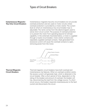
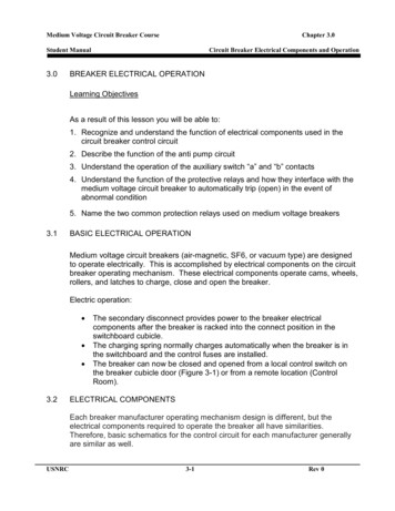
Medium Voltage Circuit Breaker CourseChapter 3.0Student Manual3.0Circuit Breaker Electrical Components and OperationBREAKER ELECTRICAL OPERATIONLearning ObjectivesAs a result of this lesson you will be able to:1. Recognize and understand the function of electrical components used in thecircuit breaker control circuit2. Describe the function of the anti pump circuit3. Understand the operation of the auxiliary switch “a” and “b” contacts4. Understand the function of the protective relays and how they interface with themedium voltage circuit breaker to automatically trip (open) in the event ofabnormal condition5. Name the two common protection relays used on medium voltage breakers3.1BASIC ELECTRICAL OPERATIONMedium voltage circuit breakers (air-magnetic, SF6, or vacuum type) are designedto operate electrically. This is accomplished by electrical components on the circuitbreaker operating mechanism. These electrical components operate cams, wheels,rollers, and latches to charge, close and open the breaker.Electric operation: 3.2The secondary disconnect provides power to the breaker electricalcomponents after the breaker is racked into the connect position in theswitchboard cubicle.The charging spring normally charges automatically when the breaker is inthe switchboard and the control fuses are installed.The breaker can now be closed and opened from a local control switch onthe breaker cubicle door (Figure 3-1) or from a remote location (ControlRoom).ELECTRICAL COMPONENTSEach breaker manufacturer operating mechanism design is different, but theelectrical components required to operate the breaker all have similarities.Therefore, basic schematics for the control circuit for each manufacturer generallyare similar as well.USNRC3-1Rev 0
Medium Voltage Circuit Breaker CourseChapter 3.0Student ManualCircuit Breaker Electrical Components and OperationCharging motors, close coils, trip coils and associated switches are required tooperate the breaker and the operating sequences are essentially the same foreach manufacturer. Basic schematics for the control circuit for eachmanufacturer generally is the same regardless of the breaker size and thecharge, close, and trip control pins on the secondary will nearly always be thesame for all plant breakers (i.e. if a DHP breaker charges on pin 5 and 6 allDHP’s). The auxiliary switch arrangements can be different and should alwaysbe verified prior to swapping cubicles.The following components are usually part of all stored energy breaker electricalcircuits:3.2.1 Secondary Disconnect: normally a plastic insulated block with silverplated copper fingers (male) or plates, which connect to a switchboard, ora mounted insulated block with silver-plated copper female receptaclepins or flat plates.3.2.2 Charging Motor: an electrical motor similar to a hand drill, which movesthe closing spring to a primed position (Figure 3-2).3.2.3 Close Coil: operates the close latch.3.2.4 Trip Coil: operates the trip latch.3.2.5 Y Relay/ Anti Pump coil: locks out the control circuit if the close operationis not completed.3.2.6 Auxiliary Switch (aux switch): a set of closed contacts and a set of opencontacts which are connected to the main operating shaft by a link andchanges position with the operation of the breaker main contacts. Theaux switch contacts, which are open when the breaker is open, are called“a contacts” and the contacts that are closed when the breaker is openare called “b contacts”. The “a contacts” are in the same position as thebreaker main contacts.3.2.7 Position Operated Switches: interlock the breaker to allow it to operateonly in the proper location, or change position and cut off a device. USNRCMotor Cut Off Switch: normally operated from a timing cam, whichoperates the switch to open the normally closed contacts and deenergizing the motor when the breaker is charged.It can also have a set of normally open contacts, which close andcomplete the circuit to the close coil.3-2Rev 0
Medium Voltage Circuit Breaker CourseChapter 3.0Student Manual 3.3Circuit Breaker Electrical Components and OperationLatch Check Switch: closes when a specific latch is in the proper position forthe breaker to operate.ELECTRICAL OPERATING SEQUENCEThe operating control voltage in most power plants is 125VDC or 220VDC and isprovided to the breaker through the secondary disconnect. The secondarydisconnect is also the interface for the auxiliary contacts on the breaker to theswitchboard, and provides indication to the system on the breaker position.A typical wiring diagram with DC control for the Westinghouse DHP is shown inFigure 3-3. We will be using this diagram to discuss the following electricaloperating sequence of a circuit breaker.3.3.1 Electrical Charging:The charging motor is energized automatically when breaker is racked in. Inthe schematic shown the motor is energized from pin 5 and 6 (Figure 3-3) onthe secondary disconnect. The motor compresses the closing spring orsprings and at the fully charged position the following occurs: 3.3.2Electrical Closing: USNRCThe charging motor is in the skip tooth position of the ratchet wheel andstops pushing the mechanism.The closing prop/latch is engaged.The timing cam is in a position, which allows the motor, cut off bracket oractu1ator to move. This will actuate the switch contacts (Figure 3-2):o LSb, which opens the circuit to the charging motor disconnectingpower to the charging motor. Ando LSa, which closes indicating that the motor has completed itscharge.The trip latch moves to a set position in preparation for closing thebreaker.The trip latch moving to the set position actuates the latch check switchLCS closing the contact and completing the circuit to the spring releasecoil (Close Coil).The close coil (Commonly called a “X coil” or spring release coil) isenergized by applying power to pin 6 and 7 (Figure 3-3) on the secondarydisconnect.3-3Rev 0
Medium Voltage Circuit Breaker CourseChapter 3.0Student ManualCircuit Breaker Electrical Components and OperationWhen the close coil is energized it will disengage the closing prop fromthe closing spring allowing the spring energy to move the contacts andclose the breaker. Y Relay (Anti Pump): The Y relay is a parallel circuit to the springrelease coil. The anti pump relay is energized at the same time as theclose coil, this will open the normally closed Y contact in the closecircuit.The purpose of the Y Relay: If the breaker does not close on the firstattempt, and the close coil remains energized, the “Y Relay” provides alock out to prevent the breaker from attempting another close. If theclose signal is initiated but not removed the breaker has the potentialto cycle through an endless close, trip, charge, close and trip cycle(Pumping). The Y coil opens the Y contact in the close circuit and aslong as the close signal is present the breaker can’t re-close.3.3.3 Tripping:When the breaker closes the circuit to the trip coil is completed by a set of“a” contacts in the Auxiliary switch which changes position with thebreaker. The close operation compresses or extended the breakeropening springs to provide tripping energy.The trip coil is energized by applying power to pin 9 and 10 on thesecondary disconnect. This pulls the trip latch, which allows the operatingmechanism to collapse, and the contacts to open.The trip coil is used to trip the breaker on normal trip from the controlpanel but is also used to trip the breaker during fault from the switchboardoverload relays.3.4PROTECTIVE RELAYSCircuit breakers designed to operate below 600 volts use trip-units and/or seriesconnected elements built directly into the circuit and are internal to the breaker.This design becomes impractical when dealing with higher voltages. Hence theprotective relay is incorporated.By using transformers to reduce large currents and high voltages to lower ranges(usually 0-5 amps and 120 volts), very simple motors or electronic circuits can beused to externally control circuit breakers. This overview will scratch the surfaceof electrical circuit protection design deeply enough to provide a basicUSNRC3-4Rev 0
Medium Voltage Circuit Breaker CourseChapter 3.0Student ManualCircuit Breaker Electrical Components and Operationunderstanding of how these devices work and how they are applied to theirappropriate systems.The primary purpose of the protective relay is minimizing damage to equipment andinterruptions to power systems when electrical failures occur. When the word“protective” is used, it means that, together with other equipment, relays help tominimize damage and improve service. The function of protective relay equipment isto quickly reenergize any element of a power system when it operates in anabnormal manner, which can damage or interfere with the effective operation of thesystem. Protective relay equipment normally is used to control circuit breakers,which in turn disconnect the faulty element of the system. Another importantfunction of protective relaying is to indicate the location and type of failure.3.4.1 Types of Protective Relays Electromechanical/Induction:Most relays of this type use either electromagnetic attraction orelectromagnetic induction principle for their operation. Theelectromagnetic, such as plunger type are instantaneous –type relaysused for detecting over current conditions. The induction-type relaysprovide over current protection with time delays. Two or three inputinduction relays are used for directional or distance protection. Balancedbeam relays are used for differential protection. For general discussion,electromechanical relays can be classified into instantaneous (magneticattraction) and time-delay (torque-controlled) units.o Instantaneous units: This type of relay unit may consist of asolenoid and plunger or a solenoid and a hinged armature.Magnetic attraction is the operating force.o Time-delay units: This type of unit consists of an induction-disk orinduction-cup that has a magnetic field applied to it by two poles ofan electromagnet which produce eddy currents in the disk or cupgenerating torque on the moveable rotor. A very simple motor. USNRCSolid-state: These relays use electronic components to provide protectivefunctions similar to those provided by electromechanical relays.This style of relay employs discrete solid-state electronic components andhas no moving parts. Most versions of solid-state relays are simpledevices that provide a single function, such as voltage, current, frequency,or phase angle measurement similar to electromechanical relays.3-5Rev 0
Medium Voltage Circuit Breaker CourseChapter 3.0Student ManualCircuit Breaker Electrical Components and Operation Microprocessor (Numerical): These devices provide multipleprotective functions in a single unit, thus reducing product andinstallation costs significantly. The basic protection principles remainthe same. Microprocessor relays are also referred to as numericalrelays because they calculate algorithms numerically. Basicconstruction consists of a microprocessor, an AC signal dataacquisition system, and memory components containing the relayalgorithms, contact inputs to control the relay, and contact outputs tocontrol other equipment. The algorithms and settings contained in therelay memory define the protection characteristics.3.4.2 Instrument transformers:Instrument transformers are an essential part of an electrical relayingsystem. The quality of instrument transformers will directly affect theoverall accuracy and performance of these systems. Instrumenttransformer performance is critical in protective relaying, since the relayscan only be as good as the instrument transformers. The basic function isto change the magnitude (but not the nature) of primary voltage andcurrent to secondary values to 120 volts and 5 or 1 amp where relays canbe applied.When relays compare the sum or difference of two or more currents or theinteraction of voltages and currents, the relative direction of the currentmust be known. The direction of current flow can be determined byknowing the instrument transformer polarity. Polarity markings arenormally shown on instrument transformers. Current Transformers: Current transformers are designed forconnection in the primary circuit (either in series or around the primarycircuit). The secondary current of the transformer bears a knownrelationship with the primary current. Any change in the primary currentis reflected in the secondary circuit. Relays are connected to thesecondary terminals of the CT’s. CT’s are made in many differentratios, different voltage insulation systems, and for differentenvironmental conditions such as indoor or outdoor use.o Accuracy class: Separate accuracy standards (ANSI) areestablished for metering CT’s and for relaying CT’s. RelayingCT’s are required to carry a much greater burden (load) ascompared to metering CT’s.USNRC3-6Rev 0
Medium Voltage Circuit Breaker CourseChapter 3.0Student ManualCircuit Breaker Electrical Components and Operationo Single and multi-ratio: CT’s may have two secondary terminalsproviding a single primary-to-secondary ratio or they may havemultiple secondary terminals (usually 5) allowing multiple options forthe required ratio. Voltage Transformers: The purpose of the VT is to provide an isolatedsecondary voltage that is and exact proportionate representation ofprimary voltage. ANSI standards for accuracy are also established forVT’s.3.4.3 Relay system characteristicsThere are four basic characteristics required for a relay to perform its functionproperly.USNRC Sensitivity: The relay must be sensitive enough to operate under theminimum conditions expected. Selectivity: Selectivity of a protective relay is its ability to recognize a faultin a particular zone of protection and trip a minimum number of circuitbreakers to clear that fault. When the relay detects fault conditions thatdon’t apply to its zone it should not operate. An example of an inherentlyselective scheme is differential relaying. The zone of protection is clearlydefined. Faults can occur upstream or downstream of the zone with noaction taken by the differential relay. Other relays should be designatedfor those specific conditions. Speed: High speed indicates that the operating time usually does notexceed 50 ms (three cycles on a 60 Hz system). The term instantaneousindicates that no intentional delay is introduced in the operation. Speed isessential in clearing a malfunctioning portion of a power system since ithas a direct bearing on the damage done by a short-circuit andconsequently, the cost and the delay in making repairs. The speed ofoperation also has a direct effect on the general stability of the powersystem. Reliability: System reliability consists of two elements, dependability andsecurity. Dependability is the degree of certainty of correct operation inresponse to system trouble, whereas security is the degree of certaintythat a relay will not operate incorrectly. Unfortunately, increasing securitytends to decrease dependability and vice versa. Modern relaying systemsare highly reliable and provide a practical compromise between securityand dependability. Most older systems have stood the test of time andadjustments to their protection are made as required.3-7Rev 0
Medium Voltage Circuit Breaker CourseChapter 3.0Student ManualCircuit Breaker Electrical Components and Operation3.4.4 Common Switchboard protective relay functionsUSNRC Over current relays: When excessive current flows in a circuit, it isnecessary to trip the circuit breaker protecting that circuit. This type ofprotection is usually provided by either time delay or instantaneousover current relays. The instantaneous relay, although inherently fast,requires a short time to operate, whereas time-delay relays haveintentional time delay built into them to provide coordination with otherover current relays for selectivity. The selectivity is obtained byadjustment of current setting and time, using the most applicable ofseveral time characteristics. The relay time characteristics differ by therate at which the time of operation of the relay decreases as thecurrent increases. This can be represented graphically by the relaysTCC curve (Time Current Characteristic). Some common relay TCCcurve families are identified as inverse, very inverse, extremelyinverse, and definite time. There are many more and custom curvescan be developed in microprocessor type relays. Over-under voltage relays: Over-under voltage relays havecharacteristics similar to the over current relays. The actuating quantityin the operating element is voltage instead of current. Voltage relaysoften combine the under-over voltage elements in one relay, withcontacts for either and under voltage or over voltage condition. Theserelays may be used to trip the breaker or sound an alarm when thesupervised voltage exceeds a predetermined limit or falls below apredetermined value. Directional relays: Directional relays are used when it is desirable totrip the circuit breaker for current flow in one direction only. This isachieved by making the relay distinguish certain differences in phaseangle between current and reference voltage or current. Thedirectional relay has a current winding and directional winding. Thecurrent winding is connected to the CT and the directional winding isconnected to the VT’s to provide the circuit voltage for polarizing theunit. The trip contacts of the relay will only operate when there issufficient current magnitude and the phase angle relationship betweenthis current and the polarizing voltages are within the predeterminedrange. The directional relay thus establishes one boundary of theprotected zone. Directional relaying is often used where coordinationbecomes a problem, such as in a tie circuit between two supplies.3-8Rev 0
Medium Voltage Circuit Breaker CourseChapter 3.0Student ManualCircuit Breaker Electrical Components and Operation Voltage or current balance relays: Voltage or current balance relayscompare the magnitudes of voltage or current present on each phase of athree-phase system. Voltage balance relays can detect a change in thephase sequence (phase reversal), loss of a phase, or an abnormalreduction in a phase voltage due to a system fault or supply problem.Current balance supervision between phases of a motor is used to protectthe machine against overheating when phase currents becomeunbalanced due to short-circuits or an open fuse. Differential relays: Differential relaying provides selectivity by providing azone of protection with a circuit of interconnected CT’s. CT’s having thesame ratio are installed in all the connections to the component to beprotected and the secondary of the CT’s are connected in parallel to therelay. As long as the current flow through the protected component isunchanged in magnitude and phase, the relay does not pick up. Such acondition would occur for a short-circuit fault outside the zone of relayprotection. Should a fault occur inside the zone of relay protection (that isbetween the CT’s), the differential relay would receive current in theoperating coil. Differential relays are designed to provide fast selectiveshort-circuit protection.3.4.5 Relays as applied to the Switchboard3.4.5.1 Main Breaker protectiono Phase and ground time-over currento Phase and ground instant over currento Phase and ground directional over currento Voltage protectiono Over/under voltageo Unbalance/phase loss/phase sequence3.4.5.2 Feeder circuit protectiono Phase and ground time-over currento Phase and ground instant over current3.4.5.3 Relay coordinationo Breakers closest to a fault should be cleared before up-streambreakers.3.4.5.4 Bus differential protectiono Over currento High impedanceUSNRC3-9Rev 0
Medium Voltage Circuit Breaker CourseChapter 3.0Student ManualCircuit Breaker Electrical Components and Operation3.4.5.5 Transformer protectiono Differentialo Sudden pressureo Backup over current3.4.5.6 Motor circuit protectiono Usually in MCCo Thermal capacityo Phase and ground faulto Overloado Locked rotor/mechanical jam/ instantaneous short circuito RTD inputso Phase sequenceo Negative sequence currento Load loss3.4.6 Circuit breaker controlUSNRC Electro-mechanical and Solid-state relays: Trip output contacts areconnected in the DC trip circuit of the relay or to the operating coil of alockout device which is in turn connected to the breaker trip circuit. Microprocessor relays: Microprocessor relays have multiple outputcontacts allowing direct trip control of the breaker for certain protectionelements and/or lockout trip control for other selected elements. Outputscontacts may be connected in the closing circuit of the breaker allowinglocal or remote closing operations through the relay. These relays arealso equipped with input sensing circuits that can be connected tobreaker auxiliary contacts or cell switches so the relay can monitor thebreaker status (open/closed, connected/disconnected). Numerous inputsare accommodated in this type of relay allowing tremendous flexibility ofcontrol over a circuit breaker. Custom logic can be applied in the relaysoftware for automatic operation of multiple circuit breakers. Relay settings: The individual elements that make up a protectiverelay are adjustable. This is where sensitivity and selectivity areapplied. The level of protection or pickup point is defined by a setting.If applicable a time delay may also be selected. Pickup settingsoptions are usually one of two formats, secondary values or per-unitvalues. Secondary values: The actual current or voltage that will be measuredat the relay terminals.3-10Rev 0
Medium Voltage Circuit Breaker CourseChapter 3.0Student ManualCircuit Breaker Electrical Components and Operationo Example: An electromechanical time over current relay has a300:5 CT connected to it. The pickup setting 3.3 is the current thatwill be measured at the relay terminals when 180 amps of primarycurrent passed through the CT. At that time the induction disc willstart to move. Per-unit values: A percentage of the CT rating.o Example: A microprocessor relay has a 300:5 CT connected to it.The per-unit value of the above setting (180 amps primary) is 0.6x CT.0.6 x 300 180 amps primary0.6 x 5 3 amps secondary3.4.7 Actually setting the relay: Electromechanical: Manually place screw in the desired tap on the relay.Turn time-dial to the desired delay band. Solid-state: Usually setting a dial on the face for the relay for the pickupand delay. Microprocessor: The easiest method is connecting a laptop to the relaywith required communication cable and utilizing the manufacturer’ssoftware to install protection and logic settings. Settings files may bedeveloped with OEM software without being connected to a relay. Thesefiles can then be installed directly into the relay without having to entersettings for each element individually.3.4.8 SummaryWithout the protective relay, the medium voltage circuit breaker is nothingmore than a switch. It needs to be told when to close and when to open.Technology offers us many new and innovative ways to do just that. Despiteall these terrific ideas we still have relays that are 30-40 years old that needto remain in service. There is quite a broad range of protective devices onemay encounter in a medium voltage switchboard. What we have shown todayis only the tip of the iceberg. Protective relaying is a science all its own.3.4.9 ANSI protective relay designation numbersThere are nearly 100 ANSI relay code numbers, the following table listsrelays that could be found on medium voltage breaker protection scheme.USNRC3-11Rev 0
Medium Voltage Circuit Breaker CourseChapter 3.0Student ManualCircuit Breaker Electrical Components and OperationTABLE 3-1CODEFUNCTION21Distance Relay is a relay that functions when the circuit admittance, impedance,or reactance increases or decreases beyond predetermined limits.25Synchronizing or Synchronism-Check Device is a device that operates whentwo a-c circuits are within the desired limits of frequency, phase angle, or voltage,to permit or to cause the paralleling of these two circuits.27Undervoltage Relay is a relay that functions on a given value of under-voltage.32Directional Power Relay is a device that functions on a desired value of powerflow in a given direction or upon reverse power resulting from arc back in theanode or cathode circuits of a power rectifier.40Field Relay is a relay that functions on a given or abnormally low value or failureof a machine field current, or on excessive value of the reactive component ofarmature current in an a-c machine indicating abnormally low field excitation.46Reverse Phase or Phase Balance Current Relay is a relay that functions whenthe polyphase currents are of reverse-phase sequence, or when the polyphasecurrents are unbalanced or contain negative phase-sequence components abovea given amount.47Phase-Sequence Voltage Relay is a relay that functions upon a predeterminedvalue of polyphase voltage in the desired phase sequence.49Machine or Transformer Thermal Relay is a relay that functions when thetemperature of a machine armature or other load-carrying winding or element of amachine or the temperature of a power rectifier or power transformer (including apower rectifier transformer) exceeds a predetermined value.50Instantaneous Overcurrent or Rate -of-Rise Relay is a relay that functionsinstantaneously on an excessive value of current or on an excessive rate ofcurrent rise, thus indicating a fault in the apparatus or circuit being protected.51A-C Time Overcurrent Relay is a relay with either a definite or inverse timecharacteristic that functions when the current in an a-c circuit exceed apredetermined value.62Time-Delay Stopping or Opening Relay is a time-delay relay that serves inconjunction with the device that initiates the shutdown, stopping, or openingoperation in an automatic sequence or protective relay system.63Liquid or Gas Pressure or Vacuum Relay is a relay that operates on givenvalues of liquid or gas pressure or on given rates of change of these values.67A-C Directional Overcurrent Relay is a relay that functions on a desired value ofa-c over-current flowing in a predetermined direction.79A-C Reclosing Relay is a relay that controls the automatic reclosing and lockingout of an a-c circuit interrupter.81Frequency Relay is a relay that functions on a predetermined value of frequencyUSNRC3-12Rev 0
Medium Voltage Circuit Breaker CourseChapter 3.0Student Manual858687USNRCCircuit Breaker Electrical Components and Operation(either under or over or on normal system frequency) or rate of change offrequency.Carrier or Pilot-Wire Receiver Relay is a relay that is operated or restrained by asignal used in connection with carrier-current or d-c pilot-wire fault directionalrelaying.Locking-Out Relay is an electrically operated hand, or electrically reset relay ordevice that functions to shut down or hold equipment out of service, or both, uponthe occurrence of abnormal conditions.Differential Protective Relay is a protective relay that functions on a percentageor phase angle or other quantitative difference of two currents or of some otherelectrical quantities.3-13Rev 0
Medium Voltage Circuit Breaker CourseChapter 3.0Student ManualCircuit Breaker Electrical Components and OperationFIGURE 3-1 Cubicle breaker control switchUSNRC3-14Rev 0
Medium Voltage Circuit Breaker CourseChapter 3.0Student ManualUSNRCCircuit Breaker Electrical Components and Operation3-15Rev 0
Medium Voltage Circuit Breaker CourseChapter 3.0Student ManualCircuit Breaker Electrical Components and OperationFigure 3-2 typical circuit breaker charging motorUSNRC3-16Rev 0
Medium Voltage Circuit Breaker CourseChapter 3.0Student ManualCircuit Breaker Electrical Components and OperationCS- BKR Control SwitchY- Control Relay (Anti-Pump)SR- Spring Release (Close)M- Spring Charging MotorLSb (NC)- Motor Cutoff SwitchLC-Latch Check Switchb- Auxiliary Switch ContactTC-Trip CoilPR- Protraction RelayG -Green indicating lightR-Red Indicating LightLSa (NO)- Permissive Closea- Auxiliary Switch ContactFigure 3-3. Typical DC Control Scheme for Westinghouse DHPUSNRC3-17Rev 0
Medium Voltage Circuit Breaker CourseChapter 3.0Student ManualCircuit Breaker Electrical Components and OperationFigure 3-4 Typical Protective RelayUSNRC3-18Rev 0
energized by applying power to pin 6 and 7 (Figure 3-3) on the secondary disconnect. Medium Voltage Circuit Breaker Course Chapter 3.0 Student Manual Circuit Breaker Electrical Components and Operation USNRC 3-4 Rev 0 When the close coil is energized it will disengage the closing prop from .