Transcription
sItem: Sentron Series Sensitrip IV Solid StateMolded Case Circuit BreakerFor Use With: JD Frame Types SJD6-B, SHJD6-B, SCJD6-BLD Frame Types SLD6-B, SHLD6-B, SCLD6-BInstallation Instructions / Instructivo de Instalación / Instructions d'installationHazardous VoltageWill cause death or serious injuryTensión peligrosa.Puede causar la muerte o lesiones graves.Tension dangereuse.Turn off and lock out all power supplying this equipmentbefore working on this device.Replace all covers before power supplying this device isturned on.Desenergice totalmente el equipo antes de instalar o darleservicio.Reemplace todas las barreras y cubiertas antes deenergizar el interruptor.Mettre hors tension et cadenasser verrouiller l’alimentationavant d’intervenir sur cet appareil.Remettre tous les couvercles en place avant de remettrecet appareil sous tension.Use only with Siemens certified Components.Utilizar únicamente con componentes certificados de Siemens.À utiliser uniquement avec les composantes certifiées Siemens.Provoquera la mort ou des blessures graves.5/16“NOTE - These instructions do not purport to cover all details or variations in equipment, or to provide for every possiblecontingency to be met in connection with installation, operation or maintenance. Should further information be desired orshould particular problems arise, which are not covered sufficiently for the purchaser’s purposes, the matter should bereferred to the local Siemens sales office. The contents of this instruction manual shall not become part of or modify any prioror existing agreement, commitment or relationship. The sales contract contains the entire obligation of Siemens. Thewarranty contained in the contract between the parties is the sole warranty of Siemens. Any statements contained herein donot create new warranties or modify the existing warranty.Trademarks - Unless otherwise noted, all names identified by are registered trademarks of Siemens AG or SiemensIndustry, Inc. The remaining trademarks in this publication may be trademarks whose use by third parties for their ownpurposes could violate the rights of the owner.NOTA - Estas instrucciones no pretenden incluir todos los detalles o variaciones de los equipos ni indicar cada posiblecontingencia que pudiese encontrar en relación con la instalación, el funcionamiento o el mantenimiento. Si desea másinformación o si surgen problemas en particular, que no estén explicados suficientemente para fines del comprador, elasunto se debe referir a la oficina de ventas local de Siemens. El contenido de este manual de instrucciones no debeformar parte ni modificar una relación, acuerdo o compromiso o previo o existente. El contrato de venta contiene toda laobligación por parte de Siemens. La garantía contenida en el contrato establecido entre las partes es la única garantía deSiemens. Las declaraciones contenidas en el presente documento no crean nuevas garantías ni modifican la que está envigor.Marcas comerciales - A menos que se indique lo contrario, todos los nombres identificados con son marcascomerciales registradas de Siemens AG o Siemens Industry, Inc. Las marcas comerciales restantes que aparecen en estapublicación pueden ser marcas comerciales cuyo uso por parte de terceros para sus propios fines podría violar losderechos del propietario.REMARQUE - Ces instructions ne prétendent pas couvrir tous les détails ou les variations de l'équipement, ni prévoirchaque éventualité pouvant être rencontrée lors de la connexion, l'exploitation ou l’entretien. Si plus d’information estdésirée ou si des problèmes particuliers surviennent, qui ne sont pas couverts suffisamment aux fins de l'acheteur, il fautadresser ces questions au bureau local de Siemens. Le contenu de ce manuel d'instruction ne fera pas partie de toutaccord, engagement ou relation préalable ou existant et ne le modifiera pas. Le contrat de vente contient l'obligationintégrale de Siemens. La garantie contenue dans le contrat entre les parties est la garantie unique offerte par Siemens.Toute autre déclaration contenue aux présentes ne crée pas de nouvelles garanties et ne modifie pas la garantie existante.Marques de commerce – Sauf indication contraire, tous les noms identifiés par MD sont des marques déposées deSiemens AG ou de Siemens Industry, Inc. Les autres marques dans cette publication peuvent être des marques dontl'utilisation par des tiers à leurs propres fins pourrait violer les droits du propriétaire.R 8 1 3 1 5 2 A 0 11 / 10
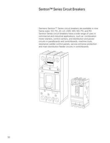
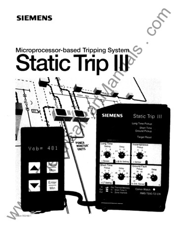
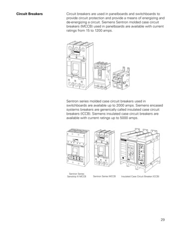
Hazardous VoltageWill cause death or serious injuryTensión peligrosa.Puede causar la muerte o lesiones graves.Tension dangereuse.Turn off and lock out all power supplying this equipmentbefore working on this device.Replace all covers before power supplying this device isturned on.Desenergice totalmente el equipo antes de instalar o darleservicio.Reemplace todas las barreras y cubiertas antes deenergizar el interruptor.Mettre hors tension et cadenasser verrouiller l’alimentationavant d’intervenir sur cet appareil.Remettre tous les couvercles en place avant de remettrecet appareil sous tension.Provoquera la mort ou des blessures graves.Installation InstructionsINTRODUCTIONThe JD and LD Frame circuit breaker lineincludes types SJD6-B, SHJD6-B,SCJD6-B, SLD6-B, SHLD6-B, andSCLD6-B circuit breaker types. These circuit breakers arelisted under UL489 and rated for operating voltages up to600 VAC, 50/60 Hz.INSTALLATIONThe JD and LD Frame circuit breakers (See Fig. 1) are foruse in individual enclosures, panelboards, or otherapproved equipment. The installation procedure consistsof inspecting, attaching required accessories, mountingthe circuit breaker and connecting and torquing the lineand load wire connectors. Mounting hardware andunmounted wire connectors (where required) are availableas separate catalog items.CIRCUIT BREAKER PREPARATIONA. Before installing or servicing the breaker, turn off andlock out all power to prevent incidental or accidentalcontact.B. Make sure that the device is suitable for the installationby comparing nameplate ratings with systemrequirements. Inspect the circuit breaker forcompleteness and check for any damage beforemounting.NOTE: Accessory installation should be completedbefore the circuit breaker is mounted and connected.(See installation instructions supplied with theaccessory before proceeding.)Fig. 1: JD, LD Frame5. Connect the line and load terminals andtorque using the values shown on the circuitbreaker nameplate.6. Connect all accessory terminals, if present.7. Check all mounting hardware for secureness.Check wire connectors for correct torquerequirements per the rating label on the front ofthe breaker.C. Depress the red trip button (See Fig 4) or turn thebreaker off before installation.MANUAL OPERATIONManual operation of the circuit breaker is controlled by thecircuit breaker handle and the PUSH-TO-TRIP button.The circuit breaker handle has three indicating positions,two of which are molded into the handle to indicate ONand OFF. The third position indicates a TRIP position andis between the ON and OFF positions. (See Fig. 4)A. Circuit Breaker ResetAfter tripping, the circuit breaker is reset by moving thecircuit breaker handle to the reset position and thenmoving the handle to the ON position.B. The PUSH-TO-TRIP ButtonThe PUSH-TO-TRIP button checks the trippingfunction and is used to manually exercise the trippingmechanism.D. To mount the circuit breaker, perform the followingsteps:1. For enclosures, panelboards and switchboardsmanufactured by Siemens Industry, Inc., follow theinstructions provided with the equipment.2. For applications where mounting is on a flatsurface of the equipment, drill and tap mountingbolt holes as shown in Fig. 2. For escutcheon cutout refer to Fig. 3.3. Ensure that any internal accessory terminals canbe properly connected with the circuit breaker inthe mounted position.4. Position the circuit breaker in the mountinglocation, install the mount information.6 / 10Max Ampere Rating200 Amps300 Amps400 Amps500 Amps600 AmpsColorGREENGREENGREENGREENGREENR813152 01
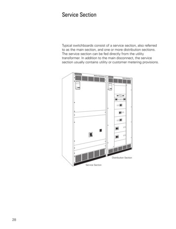
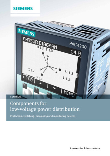
Maintenance ModeThe National Electrical Code (NFPA 70) mandates that all circuit breakers 1200A and larger be equipped with means toreduce the arc flash energy while a worker is within the circuit breaker arc-flash boundary as defined in NFPA 70E-2012,Standard for Electrical Safety in the Workplace. The Sentron Series Sensitrip IV circuit breakers with “6A” included in thecatalog number meet this requirement by use of a Maintenance Mode (MM) setting.MM Operating PrincipleThe MM is initiated by maintenance personnel pressing a normally open (NO) latching “maintenance switch” either before orupon entering a room to perform service. The first circuit breaker interprets the closed contact as a digital input command andimmediately enables the MM setting of 2xIn with no intentional delay and illuminates its local blue LED. The circuit breakerthen activates its output signal which is connected to the next circuit breaker in a series chain. The second circuit breakerreceives the input and immediately enables its MM and illuminates its local blue LED, and so on. The last circuit breaker in thesystem activates the “maintenance light” as indication that all the circuit breakers in the system are in MM.All circuit breakers that receive the input signal shall maintain MM, even with loss of control power, until a valid OFF signal isreceived. The OFF signal is initiated by maintenance personnel opening the “maintenance switch” with the control powermaintained for at least 1 second.SWITCHGEAR ECONTROL rSupplyRecommended Components:AC/DC Power Supply - Siemens, 6EP3331-6SB00-0AY0Light - Siemens, 3SU1102-6AA50-1AA0Switch - Siemens, 3SU1100-4BF11-1BA0 (keyed)Siemens, 3SU1100-2BF60-1BA0 (non-keyed)Fig. 14: Example Maintenance Mode Wiring DiagramMM Technical DataAn external 24VDC, UL Class 2, power supply is requiredto implement this feature. On the right side of the circuitbreaker are six multi-colored, 2-foot length, 18 AWG wiresfor connection. It is recommended that the interconnectionwiring be 12-18 AWG, shielded, twisted-pair and 1000feet (300-meters). Refer to Fig. 14 for an examplemaintenance mode wiring diagram. In this example, therecommended components listed can support up to 25circuit breakers.Wire ColorMM ConfigurationMM is enabled by a DIP switch under the trip unit coverand the default setting is set to MM. See Fig. 17 for DIPswitch configuration.7 / 10FunctionRED24VDC LINEBLACK24VDC COMWHITEINPUT BROWNINPUT(24VDC COM)YELLOWOUTPUT BLUEOUTPUT(24VDC COM)Rating24VDC 20%20mA max.24VDC5mA typ. sinked24VDC100mA max. sourcedR813152 01
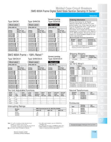
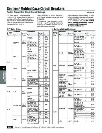
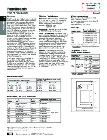
Hazardous VoltageWill cause death or serious injuryTensión peligrosa.Puede causar la muerte o lesiones graves.Tension dangereuse.Turn off and lock out all power supplying this equipmentbefore working on this device.Replace all covers before power supplying this device isturned on.Desenergice totalmente el equipo antes de instalar o darleservicio.Reemplace todas las barreras y cubiertas antes deenergizar el interruptor.Mettre hors tension et cadenasser verrouiller l’alimentationavant d’intervenir sur cet appareil.Remettre tous les couvercles en place avant de remettrecet appareil sous tension.Provoquera la mort ou des blessures graves.Zone Selective Interlocking (Optional)Sentron Series Sensitrip IV circuit breakers with “6A” included in the catalog number support Zone Selective Interlocking (ZSI).ZSI is a method which allows two or more circuit breakers to communicate with each other so that a short circuit or groundfault will be cleared by the breaker closest to the fault with a minimum time delay. The primary goal of ZSI is to limit stress onthe distribution system by clearing a fault in the shortest time without sacrificing coordination. The benefits of ZSI are lowerpotential costs of system damage due to the reduced time to clear faults and increased uptime because coordination is notsacrificed.ZSI Operating PrincipleIn a distribution system comprised of several levels,each circuit breaker affected by a short-circuitcommunicates with the circuit breaker directlydownstream, to ascertain whether the short-circuit alsooccurred. All downstream circuit breakers experiencingthe short-circuit provide a restraint signal to all circuitbreakers upstream so that the circuit breaker closest tothe short-circuit clears the fault.NON-RESTRAINTTRIPPING TIMEFUNCTIONShort Time Delaytsd(ZSI) 50msGround Fault Delaytg(ZSI) 100msZSI ExampleFig. 15 shows an example of a ZSI system with set Short Time Delay times.Short-circuit at SC1:Only CB1 establishes that a short-circuit has occurred and does not receive a restraint signal from CB2. For thisreason, CB1 trips after tsd(ZSI) 50 msShort-circuit at SC2:CB1 and CB2 establish that a short-circuit has occurred. CB2 issues a restraint signal to CB1. The t sd for CB1 will beset to its programmed setting of 300ms. CB2 does not receive a restraint signal from CB4 or CB5. For this reason,CB2 trips after tsd(ZSI) 50 msShort-circuit at SC3:CB1, CB2 and CB4 establish that a short-circuit has occurred. CB4 issues a restraint signal to CB2 and CB2 issues arestraint signal to CB1. The tsd for CB1 and CB2 will be set to their programmed setting of 300ms and 200ms,respectively. CB4 does not receive a restraint signal since it is the last circuit breaker in the system. For this reason,CB4 trips after tsd(ZSI) 50 msZSI Technical DataAn external 24VDC, UL Class 2, power supply isrequired to implement this feature. On the right side ofthe circuit breaker are six multi-colored, 2-foot length,18 AWG wires for connection. It is recommended thatthe interconnection wiring be 12-18 AWG, shielded,twisted-pair and 1000-feet (300-meters). Refer toFig. 16 for an example ZSI wiring diagram. In thisexample, the recommended components listed cansupport up to 50 circuit breakers.ZSI ConfigurationZSI is enabled by a DIP switch under the trip unit coverand the default setting is set to Maintenance Mode. SeeFig. 17 for DIP switch configuration.Wire ColorFunctionRED24VDC LINEBLACK24VDC COMWHITEINPUT BROWNINPUT(24VDC COM)YELLOWOUTPUT BLUEOUTPUT(24VDC COM)8 / 10Rating24VDC 20%20mA max.24VDC5mA typ. sinked24VDC100mA max. sourcedR813152 01
4OUTCB5INOUTCB6INOUTCB7ININSC3LOADLOADLOADLOADFig. 15: Example ZSI DCPowerSupply120VRecommended Components:AC/DC Power Supply - Siemens, CB3REDBLACKWHITEBROWNYELLOWBLUECB2Fig. 16: Example ZSI Wiring Diagram9 / 10R813152 01
Hazardous VoltageWill cause death or serious injuryTensión peligrosa.Puede causar la muerte o lesiones graves.Tension dangereuse.Turn off and lock out all power supplying this equipmentbefore working on this device.Replace all covers before power supplying this device isturned on.Desenergice totalmente el equipo antes de instalar o darleservicio.Reemplace todas las barreras y cubiertas antes deenergizar el interruptor.Mettre hors tension et cadenasser verrouiller l’alimentationavant d’intervenir sur cet appareil.Remettre tous les couvercles en place avant de remettrecet appareil sous tension.Provoquera la mort ou des blessures graves.DIP SWITCH CONFIGURATIONOn the front of the Sensitrip IV trip unit there is a 4 position configuration switch for configuring the Maintenance Mode, ZSIMode and Ground Fault Method. Use a small pocket screwdriver to open the access cover. The shipping default of this DIPswitch is with all positions in the DOWN position.Switch #1:DOWN Selects Maintenance ModeUP Selects Zone Selective Interlocking ModeSwitch #2:DOWN Disables Short Time Zone InterlockingUP Enables Short Time Zone InterlockingSwitch #3:DOWN Disables Ground Fault Zone InterlockingUP Enables Ground Fault Zone InterlockingSwitch #4:DOWN Selects Ground Fault Residual MethodUP Selects Ground Fault Ground Return MethodUPDOWNFig. 17: Configuration SwitchSTATUS INDICATORSOn the front of the Sensitrip IV trip unit there are 3 LED statusindicators that display the status of the circuit breaker: Active,Overload and Maintenance Mode. The Active and Overload LEDsare available on all circuit breaker types and the Maintenance ModeLED is only available on circuit breakers with “6A” included in thecatalog number. See Fig. 18 for location of LEDs.LEDStateMaint.ModeOFFOk. Ipri min Ipri to powertrip unitFlashing GREEN(1 Hz)Ok. Trip unit fullyoperational.Flashing GREEN( 1Hz)Ok. Ipri min Ipri to powertrip unitStatic REDTrip unit in error state.Contact technical support.OFFOkFlashing AMBERTrip pending Ipri IrStatic AmberTrip pending Ipri Ir* 115%OFFMaintenance mode OFFStatic BLUEMaintenance mode ONElectronic TestingSensitrip IV solid state molded case circuit breakersmay be tested for electronic functionality by the use ofELTPHB or EPSP18V test sets, available from localSiemens sales offices. See Fig. 18 for location of testconnector. NOTE: Time current characteristic curvesand information on factory installed accessories can beobtained from local Siemens sales offices or SiemensOnline.MaintenanceJD and LD frame circuit breakers are designed toprovide years of maintenance free service. However,some industrial users may choose to establish aninspection and maintenance procedure to be carriedout on a regular basis. For detailed information,consult applicable NEMA publication or your localSiemens sales office.NOTE: Do not spray or allow any petroleum basedchemicals, solvents or paints to contact the moldedparts or nameplates.1NationalElectrical Code is a Registered Trademark of the NationalFire Protection Association.Technical Support: Toll Free: 1-800-241-4453Subject to change without prior noticeSiemens Industry, Inc., Norcross, GA 30092Status IndicatorsFig. 18: Status Indicators and Test ConnectorTrip Unit StateActiveOverloadTest ConnectorInternet: www.usa.siemens.com/powerdistribution10 / 10 Siemens Industry Inc. 2018R813152 01
The JD and LD Frame circuit breaker line includes types SJD6-B, SHJD6-B, SCJD6-B, SLD6-B, SHLD6-B, and SCLD6-B circuit breaker types. These circuit breakers are listed under UL489 and rated for operating voltages up to 600 VAC, 50/60 Hz. INSTALLATION The JD and LD Frame circuit breakers (See Fig. 1) are for