Transcription
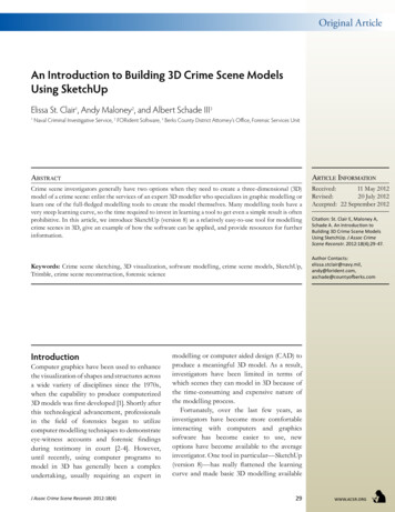
ArticleOriginal ArticleAn Introduction to Building 3D Crime Scene ModelsUsing SketchUpElissa St. Clair1, Andy Maloney2, and Albert Schade III31Naval Criminal Investigative Service, 2 FORident Software, 3 Berks County District Attorney’s Office, Forensic Services UnitAbstractArticle InformationCrime scene investigators generally have two options when they need to create a three-dimensional (3D)model of a crime scene: enlist the services of an expert 3D modeller who specializes in graphic modelling orlearn one of the full-fledged modelling tools to create the model themselves. Many modelling tools have avery steep learning curve, so the time required to invest in learning a tool to get even a simple result is oftenprohibitive. In this article, we introduce SketchUp (version 8) as a relatively easy-to-use tool for modellingcrime scenes in 3D, give an example of how the software can be applied, and provide resources for furtherinformation.Received:11 May 2012Revised:20 July 2012Accepted: 22 September 2012Keywords: Crime scene sketching, 3D visualization, software modelling, crime scene models, SketchUp,Trimble, crime scene reconstruction, forensic scienceIntroductionComputer graphics have been used to enhancethe visualization of shapes and structures acrossa wide variety of disciplines since the 1970s,when the capability to produce computerized3D models was first developed [1]. Shortly afterthis technological advancement, professionalsin the field of forensics began to utilizecomputer modelling techniques to demonstrateeye-witness accounts and forensic findingsduring testimony in court [2-4]. However,until recently, using computer programs tomodel in 3D has generally been a complexundertaking, usually requiring an expert inJ Assoc Crime Scene Reconstr. 2012:18(4)Citation: St. Clair E, Maloney A,Schade A. An Introduction toBuilding 3D Crime Scene ModelsUsing SketchUp. J Assoc CrimeScene Reconstr. 2012:18(4);29-47.Author ,aschade@countyofberks.commodelling or computer aided design (CAD) toproduce a meaningful 3D model. As a result,investigators have been limited in terms ofwhich scenes they can model in 3D because ofthe time-consuming and expensive nature ofthe modelling process.Fortunately, over the last few years, asinvestigators have become more comfortableinteracting with computers and graphicssoftware has become easier to use, newoptions have become available to the averageinvestigator. One tool in particular—SketchUp(version 8)—has really flattened the learningcurve and made basic 3D modelling available29www.acsr.org
to any investigator willing to spend a little timelearning the software.Crime Scene GraphicsCrime scene graphics are visual designsintended to illustrate details observed at aphysical location. Such graphics communicatespatial relationships to those who did notattend the scene and provide an effective wayto document a scene for subsequent analysisand presentation. They include basic, handdrawn illustrations (commonly called roughsketches), intricate, detailed drawings (knownas final sketches or diagrams), and interactive,realistic replicas (referred to as 3D models inthis article).Typical scene sketches and modelspresent a two-dimensional (2D), top-downrepresentation of the scene [5]. While 2Dsketches and models are useful for presentingthe spatial information collected at scenes, 3Dmodels can be more effective at communicatingsuch information.With SketchUp, the authors propose thatinvestigators who have no professional graphicstraining can produce realistic 3D crime scenemodels without altering the way they processthe scene and they can even create to-scale 3Dmodels if sufficient measurements are available.SketchUp’s BackgroundWhat is SketchUp, and why is it of interest tocrime scene investigators? SketchUp is a 3Dmodelling tool originally developed by @LastSoftware in 2000, and acquired by Google in2006 to provide a tool for building 3D modelsfor their Earth and Map projects. In June 2012,the rights to SketchUp were purchased byTrimble (http://www.trimble.com/). SketchUpis available for both Mac OS X and Windows.Users may download a free version of SketchUpor purchase the Pro version at http://sketchup.google.com/download/.While there are many very impressive 3Dmodelling tools currently on the market, anovice modeller with access to the internetwill find the free version of SketchUp easy toobtain and easy to learn. This means that aninvestigator can learn to create these modelsthemselves instead of relying on someone whowww.acsr.org30may not have even attended the scene. Thecost, ease-of-use, and availability of thousandsof models in the Warehouse database makeSketchUp a great option for investigators whoneed to produce 3D models of crime scenes.Basic SketchUp ConceptsBefore jumping into an example of how tobuild a 3D model, it is important to understandsome of the basic concepts used in SketchUp.When SketchUp is started, the user is presentedwith a window allowing the selection of adrawing template for the project. Templatesdo not change the way SketchUp works; theysimply provide a way to set the default scale,style, and color for new projects. Any of thesesettings may still be changed after the projectis created. SketchUp provides several built-intemplates for both imperial and metric units,and the user can create and save personalizedtemplates for future use.When the user creates a new project, they arepresented a window displaying three axes, whichrepresent the x, y, and z axes of the Cartesiancoordinate system. SketchUp uses three colorsto represent the different axes: red, green, andblue. The blue line represents up and down andthe other two make up the ground plane forthe model. Each of the axes have a solid line onone side of the origin and a dotted line on theother to help with orientation. These axes actas guidelines and are used to indicate directionand rotation, to line up objects, and to providea visual cue when moving the virtual cameraaround the scene.The Model and the CameraA SketchUp model is simply the virtual 3Dworld the modeller is creating (the crime scene)which will contain objects such as furniture,walls, victims, evidence markers, etc. Thecamera moves about this scene, allowing theuser to view objects from any angle. SketchUpprovides tools to pan, zoom, and move aboutthe scene (these tools are described below).SketchUp also provides seven standard viewsthat are helpful in positioning the camera atspecific locations relative to the scene’s axesand for focusing the camera position on thecenter of the scene. These views, accessedJ Assoc Crime Scene Reconstr. 2012:18(4)
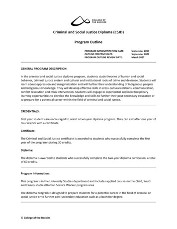
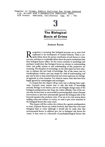
Figure 1 (top left): Top viewFigure 2 (top right): FrontviewFigure 3 (bottom left): SideviewFigure 4 (bottom right): Isoviewusing the Camera- Standard Views menu, areTop (Figure 1), Front (Figure 2), Back, Left,Right (Figure 3), Bottom, and Iso (Figure 4).Another important aspect to viewing thescene is choosing the camera projection. Thereare three different camera projections available:Parallel Projection (Figure 5), Perspective(Figure 6), and Two-Point Perspective. Thedefault camera setting is Perspective, whichmakes items closer to the viewer appear largerthan objects further away. This is a visualtechnique that makes your scene appear 3Deven though it is seen on a 2D computer screen.Consider a picture straight down some railroadtracks. The tracks appear to meet at a pointin the distance which is called the vanishingpoint. With a Parallel Projection, however, theapparent depth in the model is removed. This isespecially useful when the modeller would liketo produce a traditional, top-down, 2D sketchof the scene. Two-Point Perspective uses twovanishing points instead of one and is not really Figure 5 (left): Parallel ProjectionFigure 6 (right): PerspectiveJ Assoc Crime Scene Reconstr. 2012:18(4)31www.acsr.org
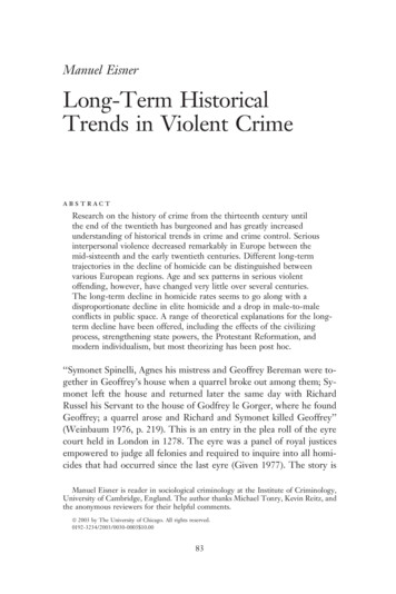
Figure 7 (top left): Shadedwith Textures styleFigure 8 (top right): ShadedstyleFigure 9 (bottom left):Monochrome styleFigure 10 (bottom right): Xray styleuseful for crime scene models, so it will not bediscussed here.The user may also add custom fixed camerapositions by using the Scene Manager window,accessed using the Window Scenes menu item.The plus icon in the upper left corner of the windowwill create a tab at the top of the viewing window,called “Scene 1.” Clicking on this tab will alwaysreturn the camera to this saved position. The usercan keep moving the camera to a new position, andrepeating the “add scene” operation until the userhas the desired number of camera positions saved.Established scenes may be renamed, rearranged,revised, or deleted under the scene managerwindow. Selected scenes may be exported as 2Dimages, 3D models, or animated “fly-through”videos (see the Advanced Topics section).www.acsr.org32StylesOne of the ways to change the look of themodel is to change the style that affects theedges and surfaces (faces) of the scene. Theoptions in the View Face Styles menu allowthe user to quickly change the visual style ofthe model to include textures (Shaded WithTextures, Figure 7) or just show the surfacesas colors (Shaded, Figure 8). Two other veryuseful styles are the Monochrome style (Figure9), which removes colors, and the X-ray style(Figure 10), which makes the entire modeltransparent. The authors have found this auseful tool when creating visually busy scenesin that it can simplify the appearance of themodel and make different viewing optionsavailable to the modeller for presentations.J Assoc Crime Scene Reconstr. 2012:18(4)
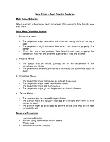
LayersA key feature of SketchUp is the ability toorganize models into layers, which is a conceptmany readers may be familiar with if they haveworked with Photoshop. Items in the scene maybe assigned to different layers created by themodeller and then the visibility of these layersmay be turned on and off. This is an extremelyvaluable tool for the modeller if they need totemporarily hide an object or objects fromview, either for editing purposes, or becausethe modeller needs to draw attention to otheritems in the scene. Grouping objects into logicallayers as the model is being built can save a lotof time when putting together presentationsor trying to demonstrate something using themodel. The user might put all the furniturein one layer, for example, so it may be easilyhidden to show only the floor plan.SketchUp provides many tools to manipulate,view, and work with your model. This articleis not going to examine all of them, but willintroduce the most basic tools used to create,modify, and view the edges and faces of amodel. SketchUp provides several tools palettesthat may be shown by selecting them in theView menu. Though most are for special tasks,the Large Tool Set palette (Figure 11) (accessedby selecting it from the View Tool Palettesmenu) contains all of the basic tools needed forthe example presented in this article. When abasic tool is selected, the status indicator at thebottom of the window provides instructions forhow to operate it. The question mark icon nextto the status indicator will open the Instructorwindow, which is a helpful guide investigatorscan use to familiarize themselves with each ofthe tools’ basic and advanced operations. Theauthors also strongly encourage new users totake advantage of free tutorials posted on theSketchUp website (http://www.sketchup.com/intl/en/training).The Line, Arc, and Freehand tools allowthe modeller to draw 2D lines. The Line toolis used to draw a line simply by clicking thestarting point of the line, clicking the endpointof the line, and then optionally typing in aJ Assoc Crime Scene Reconstr. 2012:18(4)SelectPaint BucketRectangleCircleComponent llRotateScaleTape MeasureProtractorFollow MeOffsetDimensionTextAxes3d TextOrbitPanZoomZoom ExtentsPosition CameraLook AroundFigure 11: Large Tool Setpalette Essential SketchUp Toolslength (seen in the Measurements box locatedin the bottom right corner of the window)followed by the return key, which will adjustthe line to the length specified. With the Arctool, the user clicks the start point of the arcand the end point, and then, as with the linetool, may optionally type in a number thatindicates the bulge of the arc. The Freehandtool lets the user draw arbitrary shapes, whichis converted into a series of lines by SketchUp.Often the user wants to draw circles,rectangles, or other regular, multi-sided 2Dshapes. SketchUp provides a way to quicklydraw these primitives using the Rectangle,Circle, and Polygon tools. To use the Rectangletool, the user clicks the location of the firstcorner of the rectangle, then clicks the oppositecorner when the rectangle is the correct size.As with the previous tools, the dimensions maybe entered while the tool is active to set theZoom WindowPreviousWalkSection Plane33www.acsr.org
dimensions. The Circle tool works the sameway, allowing the modeller to specify the radiusof the circle. Finally, after selecting the Polygontool, the user first specifies how many sides inthe shape—3 for a triangle, 5 for a pentagon,etc.—by typing the number followed by thereturn key, clicks the location of the center ofthe shape, and finally drags the mouse to thedesired radius. As with all the other tools, theradius may be specified by typing the radiusfollowed by the return key.So far all of these tools allow the modellerto draw 2D shapes on a specified plane. Howis this translated into 3D? When a 2D shape’sedges are closed (there are no gaps) SketchUpshades the surface of the shape to indicatethat it is a face that may now be manipulated.The Push/Pull tool lets the user click on anyface and push it or pull it using the mouse totransform a 2D shape into a 3D shape. For thistool, typing a number will adjust the size of theshape, allowing the user to make cylinders andboxes with specific dimensions.The Offset tool, which the authors findespecially useful in building walls within roomsand buildings, will copy selected coplanar lines,and reposition those lines at a uniform distancefrom the originals. To use the Offset tool, theuser clicks on a flat face, and then clicks insideor outside of the original surface to create anew border defined by the edges of the originalface. As with the other tools, the user can entera dimension to set it to a specific distance awayfrom the original edges.The Move and Rotate tools move and rotate2D and 3D figures about the model’s three axes.In order to look at the other side of the objectsin the scene, the modeller needs to move thecamera. The simplest way to do this is usingthe Orbit and Pan tools. With the Orbit toolselected, clicking and dragging the scene willrotate the scene as if it were a globe. The Pantool picks up and moves the camera withoutrotating the scene.The Scale tool may be used to re-sizeand stretch figures relative to the overalldimensions of the model, while the Dimensiontool will allow the modeller to display the toscale length, width, and/or height of an objectwith a length precision of 1/64 inch or 0.039687www.acsr.org34cm. The format of the model’s dimensions(imperial vs. metric) depends on the defaultmeasurement setting of the template originallyselected when SketchUp was first launched, butit may be manually adjusted by the user at anypoint after the start of the project.The Tape Measure and Protractor tools letthe modeller measure established distances andangles, and place guidelines at fixed distancesand angles. These guidelines are particularlyimportant in that they help a user place objectsat specific locations within the model. To usethe Tape Measure tool, the user clicks on anyedge or endpoint, moves the cursor away fromthat point, and clicks again. The Protractortool is used in the same manner, except theuser clicks on the vertex of an angle, and thentwo locations to identify the legs of the anglebeing measured. The Measurements box inthe bottom-right of the window will showthe length or angle between the starting andending points specified by the user. The usercan type in a new length if he or she would liketo resize the entire model. The “Control” keywill toggle the guide line feature and instructSketchUp to create a guide line at the endingpoint of the measurement. The user can thentype in a new length or angle for the accurateplacement of the guide line—a feature that isparticularly useful during the construction ofto-scale models.The Text and 3D Text tools may be usedto label objects or particular points of interestin the scene. The Text tool creates 2D textboxes within the model that may be placed atstationary locations within the viewport, orattached to objects within the scene by leaderand a point or arrow. Text created using thistool shifts as the model is rotated in order tostay oriented towards the camera. In contrast,the 3D Text tool produces 2D text tags and 3Dtext objects that remain in place as the model isrotated (Figure 12). The user may edit the size,color, and font style of text created by eithertool.The Paint Bucket tool allows the user toselect and apply any solid color or materialstored in the SketchUp materials library. Thesematerials are abundant and include images ofdifferent types of wood, metal, textiles, andJ Assoc Crime Scene Reconstr. 2012:18(4)
vegetation. Users may edit any of the preloaded materials or upload new images to addcolor and texture to an object in their model.Figure 12: 2D and 3D Text.Note that the 3D textremains on the surfacewhereas the 2D textrotates to face the camera. The 3D WarehouseThe SketchUp 3D Warehouse is one of the bestbenefits of using SketchUp for crime scenesketching. The 3D Warehouse is a free, onlinedatabase containing thousands of models thathave been uploaded by SketchUp users since2006. SketchUp users may access the databasethrough the online site (http://sketchup.com/3dwarehouse/) or through the SketchUpprogram under File Warehouse Get Models.Then it is simply a matter of doing a keywordsearch for an object the modeller would like toimport into their sketch. For example, a searchfor the word couch will return thousands ofmodels of couches, loveseats, and chairs that amodeller can download (Figure 13).The sophistication of the objects within the3D Warehouse vary quite a bit, so a modellermay have to spend several minutes hunting forthe right object for their model. Once objectshave been imported into the scene, they maybe resized and edited as needed. The 3DWarehouse is constantly being updated withnew models from the SketchUp community,so it is always a good first stop if a modellerneeds to add something to their crime scene.Adding models to the 3D Warehouse is also Figure 13: Screenshotof search results withinWarehouse.J Assoc Crime Scene Reconstr. 2012:18(4)35www.acsr.org
Figure 14: View from thekitchen door into thekitchen. Figure 15: View of thedining room through to thekitchen.www.acsr.org36J Assoc Crime Scene Reconstr. 2012:18(4)
Figure 16: Hand-drawnsketches of the kitchen(left) and dining room(right).possible. If an investigator creates a model ofsomething from a crime scene which mightbe useful to others, it is simple to add it tothe 3D Warehouse for other investigators andSketchUp users.Figure 17: Importing the2D hand-drawn sketchesinto SketchUp. Scene Exampleto build the 3D model of the crime scene,it is important to note that the steps andmethods presented for this example are justone way of building a 3D crime scene modelusing SketchUp. There are many other tricksand techniques that may work better for agiven modeller, so users are encouraged toexperiment to find a workflow that suits them.To present an example of how one mightbuild a 3D model from a 2D sketch of acrime scene, the authors have chosen a smalltwo-room scene from a homicide in Reading,Pennsylvania, USA (Figures 14 and 15).Two males entered a residence armed witha hammer and a baseball bat and struck thevictim approximately 23 times about the headand body. The assault started in the kitchenand ended in the dining room, with the victimending up in the doorway between the tworooms. Detectives subsequently sketched thescene by hand and documented the scene witha laser measuring tool and a tape measure usingthe baseline method.Two hand-drawn sketches from the crimescene (Figure 16) were used to build the 3Dmodel in SketchUp. Measurements of windowopenings, doorways, evidence locations, bodymeasurements, and some of the furniturewere recorded on separate sheets and are notpresented here.Before outlining the steps that were takenJ Assoc Crime Scene Reconstr. 2012:18(4)37www.acsr.org
Figure 18: Using theRectangle, Offset, Eraser,and Dimension tools.Importing The Rough SketchesAdding FurnitureA new project was created by openingSketchUp and choosing the Plan View - Feetand Inches template. Next, scanned copies ofthe hand-drawn sketches were imported andplaced in the x-y plane (the top-down view) asa reference while building the model (Figure17). This provides a reference so the user doesnot have to switch between programs to lookat the sketch, and permits a side-by-side visualcomparison as the user is modelling.For each piece of furniture in the room, asearch was conducted using the 3D Warehouseto find furniture that closely matched theactual furniture in the crime scene photos.Any furniture that was not found online wasmodelled separately and then imported intothe scene. The size and colors of the objectswere adjusted to match the dimensions andcolors of the physical objects and the objectswere placed in the correct location based on themeasurements from the crime scene (Figure19).Room OutlineAn outline of the rooms was created correspondingto the measurements from the sketch. Usingthe Rectangle tool, the floor was added with thespecified dimensions. The Offset tool was thenused to add thickness to the walls and the Erasertool used to create the doorway. Finally, theDimension tool was used to add the dimensions ofeach room to the model (Figure 18).www.acsr.org38Markers & GuidelinesGuidelines are instrumental for placing objectsat known locations in the scene. For eachevidence location, the Guideline tool was usedto measure and mark the location within thescene and then a model of an evidence markermodel was positioned accordingly (Figure 20).J Assoc Crime Scene Reconstr. 2012:18(4)
Figure 19: Top-view ofscene after furniture isadded. Figure 20: Using theGuideline tool to positionevidence markers.J Assoc Crime Scene Reconstr. 2012:18(4)39www.acsr.org
Figure 21: Adjusting thecontrol points to pose amuryoung model. Figure 22: Final pose of themuryoung model beforeimporting into the crimescene.www.acsr.org40J Assoc Crime Scene Reconstr. 2012:18(4)
Figure 23: Body importedand placed in the crimescene model (note thatthe control points layer hasbeen hidden).Keeping in mind that the investigator probablydoes not want the evidence markers visibleall the time, the markers were created on aseparate layer within the model, which allowsthe user to hide them using the Layers window.The BodyPlacing a body or bodies in a 3D model canbe challenging. One method is to use othersoftware, such as SmithMirco’s Poser (http://poser.smithmicro.com), to build the modelFigure 24: Adding walls tothe model. and then to import it into the SketchUp crimescene. For this example, however, the authorsused the Muryoung Standard Pose posablebody found in the 3D Warehouse (search for“muryoung”) and reference photos from thescene to create a model of a body in the correctpose. The muryoung model was built in such away that control points on the body may be usedto pose it in the correct orientation and thenthese control points, which are on a separatelayer, may be hidden in the final presentation(Figures 21 through 23). Some modellers preferto work with models like this in a separateSketchUp file and then import them into theirmain crime scene model, as the authors havedone here. Using separate files may also beuseful if there are multiple people collaboratingon creating one crime scene model.The WallsNow that all the objects were placed within thescene, the next step was to use the Offset, Push/Pull, and Eraser tools to create the walls ofthe dining room and kitchen. Some modellersJ Assoc Crime Scene Reconstr. 2012:18(4)41www.acsr.org
Figure 25: Adding detail tothe model. Figure 26: Top view, without perspective. Figure 27: Top view, withperspective.www.acsr.org42J Assoc Crime Scene Reconstr. 2012:18(4)
Figure 28 (top left):Photograph of kitchen.Figure 29 (bottom left):View within SketchUpmodel corresponding withview captured in photograph displayed as Figure28.Figure 30 (top right):Photograph of body.Figure 31 (bottom right):View within SketchUpmodel corresponding withview captured in photograph displayed as Figure30.prefer to do this step at the beginning whenthey build the outline of the room and thenhide the walls using layers, but in this instancethe modeller added them towards the end ofconstruction (Figure 24).Adding DetailFigure 32: Photograph ofbody. At this point, the main part of the model wascomplete, so the final step was to add someextra detail. For this example, the windows anddoors were added and textures added to thefloor, furniture, and other surfaces (Figure 25).Pan, and Zoom tools. These camera locationsmay be saved using the Scene Manager,described earlier, so they can be accessed witha simple click when the investigator needs topresent their model and may also be used forsimple animated walkthroughs of the scene(see the Advanced Topics section).Any view of the scene may be exported asa 2D image, like a snapshot from the virtualcamera, using the File Export 2D Graphicmenu item. SketchUp will save these imagesDifferent ViewsFigure 33: View withinSketchUp model corresponding with view captured in photograph displayed as Figure 32.Once the investigator has completed theirmodel, there are many options for viewing itand displaying it to others. As discussed earlier,there are several built-in camera views that theuser can select from the Camera StandardViews menu. One of the most useful is obviouslythe top-down, or birds-eye, view. The cameraprojection may also be chosen in the Cameramenu to show something like an architecturalfloor plan without perspective (Figure 26) or a3D perspective view (Figure 27).Final ResultsThe final model can now be compared directlywith photos from the crime scene by movingthe camera around the scene using the Orbit,J Assoc Crime Scene Reconstr. 2012:18(4)43www.acsr.org
in jpeg, png, or tiff format. For each of thereference photos, the camera was placed inapproximately the same location and theimages exported from SketchUp (Figures 28through 33).Advanced TopicsThis article has introduced some of the basicconcepts, tools, and functionality availablein SketchUp. There are several other, moreadvanced, capabilities that have not beencovered but may be of interest to users afterthey become familiar the basic capabilities ofSketchUp.PhotographyAs discussed in the introduction, the level ofrealism of a model can vary dramatically. Withphotography, the type and number of photosmay depend on whether the investigator isplanning to build a more sketch-like 3D modelor whether they aim to build a to-scale realisticrendering of the scene. If the investigator isintending to build a more realistic model, thenrepresentative texture photos of walls, floors,furniture, and other objects in the scene shouldbe shot so they may be used within SketchUpto texture the models.Regardless of the level of realism planned,it is always helpful to have numerous referencephotos of the scene from different anglesand positions. These will be instrumental inpositioning objects, setting colors, and choosingmodels from the 3D warehouse to representfurniture and other objects in the scene. If amodel of a specific object is not available inthe 3D Warehouse, then the investigator mayhave to create their own, so, in addition to themeasurements, reference photos are essential.If there are bodies to be documented andplaced in the model, then photos will be crucialfor posing the body model in SketchUp; thus itis highly advisable to take many photos fromdifferent angles.Scene AnimationUsing the Scene Manager discussed earlier,the user can add several camera positionsthroughout the scene. To see the animation,www.acsr.org44the user right-clicks a scene tab and selects PlayAnimation. SketchUp will cycle through allsaved camera views, starting from the scene tabthat was selected. The time it takes the camerato transition from scene to scene may be editedunder the Animation section of the Model Infowindow located under Window Model Info.When the user is satisfied with the movementof the camera from the first scene to the lastscene, they can export the animation as anAudio Video Interleaved (.avi) file. This filemay be opened with an audio/video player likeWindows Media Player or QuickTime. Thisanimation might be used to virtually “walk”someone through a crime scene.Extending SketchUpPlug-ins, optional software add-ons that allowusers to automate tasks and add capabilitiesto SketchUp, can either be written using aprogrammer’s interface and a language likeC or using a scripting language calledRuby. Plug-ins are available for both SketchUpand SketchUp Pro and are a great way to addfeatures to SketchUp that are not included aspart of the basic software.A good example—one that may be usefulfor crime scene presentations—is the freeAdvanced Camera Tools plug-in created forSketchUp Pro l#advcam).Thisprovides more refined control of the camera,allowing adjustment of focal length and otherphysical camera settings, that can help the usercreate views of their 3D model that more closelyresemble a physical photo for comparison.While plug-ins are not required to completea high-quality crime scene mo
SketchUp a great option for investigators who need to produce 3D models of crime scenes. Basic SketchUp Concepts Before jumping into an example of how to build a 3D model, it is important to understand some of the basic concepts used in SketchUp. When SketchUp is started, the user is presented with a window allowing the selection of a