Transcription
Powerware 9170 UPS3–18 kVAUser’s Guide
Requesting a Declaration of ConformityUnits that are labeled with a CE mark comply with the following harmonized standards and EU directives:SHarmonized Standards: EN 50091-1-1 and EN 50091-2; IEC 60950 Third EditionSEU Directives:73/23/EEC, Council Directive on equipment designed for use within certain voltage limits93/68/EEC, Amending Directive 73/23/EEC89/336/EEC, Council Directive relating to electromagnetic compatibility92/31/EEC, Amending Directive 89/336/EEC relating to EMCThe EC Declaration of Conformity is available upon request for products with a CE mark. For copies of the ECDeclaration of Conformity, contact:Eaton Power Quality OyKoskelontie 13FIN-02920 EspooFinlandPhone: 358-9-452 661Fax: 358-9-452 665 68Powerware, LanSafe, and FERRUPS are registered trademarks and ConnectUPS and BestDock are trademarks ofEaton Power Quality Corporation.Torx is a registered trademark of Textron, Inc.ECopyright 2000–2006 Eaton Corporation, Raleigh, NC, USA. All rights reserved. No part of this document may bereproduced in any way without the express written approval of Eaton Corporation.
Class A EMC StatementsFCC Part 15NOTE This equipment has been tested and found to comply with the limits for a Class A digital device, pursuant topart 15 of the FCC Rules. These limits are designed to provide reasonable protection against harmful interferencewhen the equipment is operated in a commercial environment. This equipment generates, uses, and can radiateradio frequency energy and, if not installed and used in accordance with the instruction manual, may cause harmfulinterference to radio communications. Operation of this equipment in a residential area is likely to cause harmfulinterference in which case the user will be required to correct the interference at his own expense.ICES-003This Class A Interference Causing Equipment meets all requirements of the Canadian Interference CausingEquipment Regulations ICES-003.Cet appareil numérique de la classe A respecte toutes les exigences du Reglement sur le matériel brouilleur duCanada.EN 50091-2Some configurations are classified under EN 50091-2 as “Class-A UPS for Unrestricted Sales Distribution.” Forthese configurations, the following applies:WARNING This is a Class A-UPS Product. In a domestic environment, this product may cause radio interference, inwhich case, the user may be required to take additional measures.VCCI Notice
Special SymbolsThe following are examples of symbols used on the UPS or accessories to alert you to importantinformation:RISK OF ELECTRIC SHOCK - Indicates that a risk of electric shock is present and theassociated warning should be observed.CAUTION: REFER TO OPERATOR’S MANUAL - Refer to your operator’s manual foradditional information, such as important operating and maintenanceinstructions.This symbol indicates that you should not discard the UPS or the UPS batteriesin the trash. This product contains sealed, lead-acid batteries and must bedisposed of properly. For more information, contact your local recycling/reuse orhazardous waste center.This symbol indicates that you should not discard waste electrical or electronicequipment (WEEE) in the trash. For proper disposal, contact your localrecycling/reuse or hazardous waste center.
Table of Contents1Introduction . . . . . . . . . . . . . . . . . . . . . . . . . . . . . . . . . . . . . . . . . . . . . . . . . . . . . . . .1Safety Warnings . . . . . . . . . . . . . . . . . . . . . . . . . . . . . . . . . . . . . . . . . . . . . . . . . . . . . . . . . . . . . . . . . . . . .Physical Features . . . . . . . . . . . . . . . . . . . . . . . . . . . . . . . . . . . . . . . . . . . . . . . . . . . . . . . . . . . . . . . . . . . .25Installation Setup . . . . . . . . . . . . . . . . . . . . . . . . . . . . . . . . . . . . . . . . . . . . . . . . . . .9Equipment Clearances . . . . . . . . . . . . . . . . . . . . . . . . . . . . . . . . . . . . . . . . . . . . . . . . . . . . . . . . . . . . . . . . .Location Requirements . . . . . . . . . . . . . . . . . . . . . . . . . . . . . . . . . . . . . . . . . . . . . . . . . . . . . . . . . . . . . . . .UPS Setup . . . . . . . . . . . . . . . . . . . . . . . . . . . . . . . . . . . . . . . . . . . . . . . . . . . . . . . . . . . . . . . . . . . . . . . . .Three- and Six-Slot Cabinets . . . . . . . . . . . . . . . . . . . . . . . . . . . . . . . . . . . . . . . . . . . . . . . . . . . . . . . . . .Nine- and Twelve-Slot Cabinets . . . . . . . . . . . . . . . . . . . . . . . . . . . . . . . . . . . . . . . . . . . . . . . . . . . . . . .Caster Cart Installation (Three- and Six-Slot Cabinets) . . . . . . . . . . . . . . . . . . . . . . . . . . . . . . . . . . . . . . . . . .Stabilizer Bracket Installation (Twelve-Slot Cabinet Only) . . . . . . . . . . . . . . . . . . . . . . . . . . . . . . . . . . . . . . . .Rack-Mount Installation (Three- and Six-Slot Cabinets) . . . . . . . . . . . . . . . . . . . . . . . . . . . . . . . . . . . . . . . . . .Floor Anchor Kit Installation . . . . . . . . . . . . . . . . . . . . . . . . . . . . . . . . . . . . . . . . . . . . . . . . . . . . . . . . . . . . .Moving the Cabinets . . . . . . . . . . . . . . . . . . . . . . . . . . . . . . . . . . . . . . . . . . . . . . . . . . . . . . . . . . . . . . . . . .9101010111213141617UPS with Bypass Electrical Installation . . . . . . . . . . . . . . . . . . . . . . . . . . . . . . . . . .19Input Current Ratings . . . . . . . . . . . . . . . . . . . . . . . . . . . . . . . . . . . . . . . . . . . . . . . . . . . . . . . . . . . . . . . . . .Bypass Switches . . . . . . . . . . . . . . . . . . . . . . . . . . . . . . . . . . . . . . . . . . . . . . . . . . . . . . . . . . . . . . . . . . . . .UPS Installation with an External Bypass Switch . . . . . . . . . . . . . . . . . . . . . . . . . . . . . . . . . . . . . . . . . . . . . .System Wiring Diagrams . . . . . . . . . . . . . . . . . . . . . . . . . . . . . . . . . . . . . . . . . . . . . . . . . . . . . . . . . . . . . . .21222533UPS Electrical Installation . . . . . . . . . . . . . . . . . . . . . . . . . . . . . . . . . . . . . . . . . . . .39Input Current Ratings . . . . . . . . . . . . . . . . . . . . . . . . . . . . . . . . . . . . . . . . . . . . . . . . . . . . . . . . . . . . . . . . . .UPS Electrical Installation . . . . . . . . . . . . . . . . . . . . . . . . . . . . . . . . . . . . . . . . . . . . . . . . . . . . . . . . . . . . . .System Wiring Diagrams . . . . . . . . . . . . . . . . . . . . . . . . . . . . . . . . . . . . . . . . . . . . . . . . . . . . . . . . . . . . . . .404248Isolated Output Wiring Diagrams . . . . . . . . . . . . . . . . . . . . . . . . . . . . . . . . . . . . . . .53Neutral-to-Ground Bonding for Isolated Output . . . . . . . . . . . . . . . . . . . . . . . . . . . . . . . . . . . . . . . . . . . . . . .System Wiring Diagrams . . . . . . . . . . . . . . . . . . . . . . . . . . . . . . . . . . . . . . . . . . . . . . . . . . . . . . . . . . . . . . .54566Battery Cabinet Installation . . . . . . . . . . . . . . . . . . . . . . . . . . . . . . . . . . . . . . . . . . . .617UPS Startup . . . . . . . . . . . . . . . . . . . . . . . . . . . . . . . . . . . . . . . . . . . . . . . . . . . . . . . .67Power and Battery Module Installation . . . . . . . . . . . . . . . . . . . . . . . . . . . . . . . . . . . . . . . . . . . . . . . . . . . . .Startup for Plug-Receptacle Units . . . . . . . . . . . . . . . . . . . . . . . . . . . . . . . . . . . . . . . . . . . . . . . . . . . . . . . . .68692345EATON Powerware 9170 UPS (3–18 kVA) User’s Guide S 164201393 Rev C www.powerware.comi
TABLE OF CONTENTSStartup for Hardwired Units . . . . . . . . . . . . . . . . . . . . . . . . . . . . . . . . . . . . . . . . . . . . . . . . . . . . . . . . . . . . .Initial Startup Parameters . . . . . . . . . . . . . . . . . . . . . . . . . . . . . . . . . . . . . . . . . . . . . . . . . . . . . . . . . . . . . .7275Operation . . . . . . . . . . . . . . . . . . . . . . . . . . . . . . . . . . . . . . . . . . . . . . . . . . . . . . . . . .79Turning the UPS On . . . . . . . . . . . . . . . . . . . . . . . . . . . . . . . . . . . . . . . . . . . . . . . . . . . . . . . . . . . . . . . . . . .Removing Input Power . . . . . . . . . . . . . . . . . . . . . . . . . . . . . . . . . . . . . . . . . . . . . . . . . . . . . . . . . . . . . . . . .Front Panel Display . . . . . . . . . . . . . . . . . . . . . . . . . . . . . . . . . . . . . . . . . . . . . . . . . . . . . . . . . . . . . . . . . . .Using the Front Panel Display . . . . . . . . . . . . . . . . . . . . . . . . . . . . . . . . . . . . . . . . . . . . . . . . . . . . . . . . . . . .Parameters . . . . . . . . . . . . . . . . . . . . . . . . . . . . . . . . . . . . . . . . . . . . . . . . . . . . . . . . . . . . . . . . . . . . . . . . .Changing Parameter Settings . . . . . . . . . . . . . . . . . . . . . . . . . . . . . . . . . . . . . . . . . . . . . . . . . . . . . . . . . . . .Reading the Powerware 9170 System Logs . . . . . . . . . . . . . . . . . . . . . . . . . . . . . . . . . . . . . . . . . . . . . . . . .Inverter Log . . . . . . . . . . . . . . . . . . . . . . . . . . . . . . . . . . . . . . . . . . . . . . . . . . . . . . . . . . . . . . . . . . . . . .Alarm Log . . . . . . . . . . . . . . . . . . . . . . . . . . . . . . . . . . . . . . . . . . . . . . . . . . . . . . . . . . . . . . . . . . . . . . .Battery Test . . . . . . . . . . . . . . . . . . . . . . . . . . . . . . . . . . . . . . . . . . . . . . . . . . . . . . . . . . . . . . . . . . . . . . . .Menu Map . . . . . . . . . . . . . . . . . . . . . . . . . . . . . . . . . . . . . . . . . . . . . . . . . . . . . . . . . . . . . . . . . . . . . . . . .8181828385858686878889Communication . . . . . . . . . . . . . . . . . . . . . . . . . . . . . . . . . . . . . . . . . . . . . . . . . . . . .91Powerware LanSafe Power Management Software . . . . . . . . . . . . . . . . . . . . . . . . . . . . . . . . . . . . . . . . . . . .Optional Interface Kits . . . . . . . . . . . . . . . . . . . . . . . . . . . . . . . . . . . . . . . . . . . . . . . . . . . . . . . . . . . . . . . . .Communication Slots . . . . . . . . . . . . . . . . . . . . . . . . . . . . . . . . . . . . . . . . . . . . . . . . . . . . . . . . . . . . . . . . . .ConnectUPS Web/SNMP Card (BD Model) . . . . . . . . . . . . . . . . . . . . . . . . . . . . . . . . . . . . . . . . . . . . . . . .Relay Interface Card (BestDock Model) . . . . . . . . . . . . . . . . . . . . . . . . . . . . . . . . . . . . . . . . . . . . . . . . . .Dedicated Input Signals . . . . . . . . . . . . . . . . . . . . . . . . . . . . . . . . . . . . . . . . . . . . . . . . . . . . . . . . . . . . . . . .DB-9 Communication Port . . . . . . . . . . . . . . . . . . . . . . . . . . . . . . . . . . . . . . . . . . . . . . . . . . . . . . . . . . . . . .9191929292929410 Maintenance . . . . . . . . . . . . . . . . . . . . . . . . . . . . . . . . . . . . . . . . . . . . . . . . . . . . . . .95Routine Maintenance . . . . . . . . . . . . . . . . . . . . . . . . . . . . . . . . . . . . . . . . . . . . . . . . . . . . . . . . . . . . . . . . .Storage Temperature . . . . . . . . . . . . . . . . . . . . . . . . . . . . . . . . . . . . . . . . . . . . . . . . . . . . . . . . . . . . . . . . . .External Bypass Switch (Make-Before-Break Only) Operation . . . . . . . . . . . . . . . . . . . . . . . . . . . . . . . . . . . . .Battery Replacement . . . . . . . . . . . . . . . . . . . . . . . . . . . . . . . . . . . . . . . . . . . . . . . . . . . . . . . . . . . . . . . . . .Power Module Replacement . . . . . . . . . . . . . . . . . . . . . . . . . . . . . . . . . . . . . . . . . . . . . . . . . . . . . . . . . . . . .959696969711 Specifications . . . . . . . . . . . . . . . . . . . . . . . . . . . . . . . . . . . . . . . . . . . . . . . . . . . . . .9912 Troubleshooting . . . . . . . . . . . . . . . . . . . . . . . . . . . . . . . . . . . . . . . . . . . . . . . . . . . . .107Alarms . . . . . . . . . . . . . . . . . . . . . . . . . . . . . . . . . . . . . . . . . . . . . . . . . . . . . . . . . . . . . . . . . . . . . . . . . . . .Service and Support . . . . . . . . . . . . . . . . . . . . . . . . . . . . . . . . . . . . . . . . . . . . . . . . . . . . . . . . . . . . . . . . . .10911313 Warranty . . . . . . . . . . . . . . . . . . . . . . . . . . . . . . . . . . . . . . . . . . . . . . . . . . . . . . . . . .115Two-Year Limited Warranty (US and Canada) . . . . . . . . . . . . . . . . . . . . . . . . . . . . . . . . . . . . . . . . . . . . . . . . .Ten-Year Pro-Rated Limited Warranty (US and Canada) . . . . . . . . . . . . . . . . . . . . . . . . . . . . . . . . . . . . . . . . .Load Protection Guarantee (US and Canada) . . . . . . . . . . . . . . . . . . . . . . . . . . . . . . . . . . . . . . . . . . . . . . . . .11511711989iiEATON Powerware 9170 UPS (3–18 kVA) User’s Guide S 164201393 Rev C www.powerware.com
Chapter 1IntroductionThe Powerware 9170 uninterruptible power system (UPS) is a modularUPS that contains battery modules and power control modules (referredto as power modules). These modules plug into a rack cabinet structurecontaining additional control, communication, and display functions thatenable integrated control of all power modules. The UPS is housed in asingle cabinet, with extra battery capacity housed in auxiliary batterycabinets.The pluggable power modules can be removed and replaced(hot-swapped) without powering the UPS down if the UPS has sufficientredundant capacity. Battery modules may also be hot-swapped formaintenance. Power control circuitry in the cabinet senses problems inpower modules, and automatically transfers control and load to theremaining power modules.All power modules share the load requirements equally. For example,three power modules are capable of supplying a total of 9 kVA. If a loadrequires only 4.5 kVA, each power module supplies 1.5 kVA to theoutput. If one power module is removed or for some reason fails, eachof the two remaining power modules would supply half of the load, or2.25 kVA. In other words, redundancy exists when the load can besupplied by less than all of the installed power modules.The UPS can be configured with up to seven power and/or optionalbattery charger modules; its output is limited such that an excessnumber of power modules allow the failure of one or more moduleswithout causing the UPS to lose any functionality.To permit UPS removal from the power path while maintaining power tothe loads, an external bypass switch is required. This switch is optionalbut recommended for system serviceability.EATON Powerware 9170 UPS (3–18 kVA) User’s Guide S 164201393 Rev C www.powerware.com1
INTRODUCTIONSafety WarningsIMPORTANT SAFETY INSTRUCTIONSSAVE THESE INSTRUCTIONSThis manual contains important instructions that you should follow during installation andmaintenance of the UPS and batteries. Please read all instructions before operating theequipment and save this manual for future reference.CAUTIONS Split-phase power modules (model ASY-0673) have brown labels on the front andproduce two output voltages: 100/100 for 200, 110/110 for 220, 120/120 for 240,120/120 for 208, or 127/127 for 220 Vac. Universal power modules (model ASY-0674)have black labels on the front and produce a single output voltage: 200, 208, 220, 230,or 240 Vac. DO NOT mix the two types of power modules in the same Powerware 9170 cabinet.S Do NOT install more than seven power and/or optional battery charger modules in thesystem.S Battery modules to be used in the Powerware 9170 system are model ASY-0529. Eachbattery module weighs 14 kg (30 lb). Use care in lifting and moving battery modules.S All input and output wiring must be copper and adequate to carrying currents as listed inTable 16 and Table 17 on pages 100 and 102.S Torque all bolts holding input and output power conductors to values specified in Table 2on page 22.S The user is required to provide power input and output disconnect devices for the UPS.These must be within sight of the UPS and easily accessible. For a plug-receptacle unit,the plug serves as the power input disconnect device, which must also be readilyaccessible.2EATON Powerware 9170 UPS (3–18 kVA) User’s Guide S 164201393 Rev C www.powerware.com
INTRODUCTIONConsignes de SécuritéCONSIGNES DE SÉCURITÉ IMPORTANTESCONSERVER CES INSTRUCTIONSCe manuel comporte des instructions importantes que vous êtes invité à suivre lors de touteprocédure d’installation et de maintenance des batteries et de l’onduleur. Veuillez consulterentièrement ces instructions avant de faire fonctionner l’équipement et conserver ce manuelafin de pouvoir vous y reporter ultérieurement.ATTENTION!S Les blocs de puissance à phase auxiliaire (modèle ASY-0673) sont dotés d’étiquettesmarron sur le dessus et produisent deux tensions de sortie : 100/100 pour 200, 110/110pour 220, 120/120 pour 240, 120/120 pour 208, ou 127/127 pour 220 Vca. Les blocs depuissance universels (modèle ASY-0674) sont dotés d’étiquettes noires sur le dessus etproduisent une seule tension de sortie : 200, 208, 220, 230 ou 240 Vca. NE mélangezPAS les deux types de blocs de puissance dans le même module d’unité d’alimentation.S N’installez PAS plus de sept chargeurs de batteries optionnels et/ou de puissance dansle système.S Les modules de batterie à utiliser dans le système Powerware 9170 correspondent aumodèle ASY-0529. Chaque module de batterie pèse 14 kg (30 lb). Levez ou déplacez lesmodules de batterie avec soin.S Tous les câblages d’entrée et de sortie doivent être en cuivre et doivent prendre encharge les courants répertoriés dans les Table 16 et Table 17 des pages 100 et 102.S Couplez tous les boulons en maintenant les conducteurs de sortie sur les valeursindiquées dans le Table 2 à la page 22.S L’utilisateur doit fournir des appareils de déconnexion de l’alimentation en entrée et ensortie pour l’onduleur. Ceux-ci doivent se trouver dans le périmètre de l’onduleur et êtrefaciles d’accès. En ce qui concerne l’unité de prise, la prise sert d’appareil dedéconnexion de l’alimentation en entrée, laquelle doit également être facile d’accès.EATON Powerware 9170 UPS (3–18 kVA) User’s Guide S 164201393 Rev C www.powerware.com3
INTRODUCTIONAdvertencias de SeguridadINSTRUCCIONES DE SEGURIDAD IMPORTANTESGUARDE ESTAS INSTRUCCIONESEste manual contiene instrucciones importantes que debe seguir durante la instalación y elmantenimiento del SIE y de las baterías. Por favor, lea todas las instrucciones antes deponer en funcionamiento el equipo y guarde este manual para referencia en el futuro.PRECAUCIÓNS Los módulos de potencia de fase dividida (modelo ASY-0673) portan etiquetas de colorcafé en la parte delantera y producen dos voltajes de salida: 100/100 para 200, 110/110para 220, 120/120 para 240, 120/120 para 208 ó 127/127 para 220 Vca. Los módulos depotencia universal (modelo ASY-0674) portan etiquetas negras en la parte delantera yproducen un solo voltaje de salida: 200, 208, 220, 230 ó 240 Vca. NO combine los dostipos de módulos de potencia en el mismo gabinete de la Unidad de distribución dealimentación.S NO instale en los módulos de potencia del sistema más de siete módulos de potenciay/o de cargadores opcionales de baterías.S Los módulos de baterías a utilizarse en el sistema Powerware 9170 son del modeloASY-0529. Cada módulo de batería pesa 14 kg (30 lb). Levante y mueva con cuidado losmódulos de baterías.S Todo el cableado de entrada y de salida debe ser de cobre y del tipo adecuado paratransportar las corrientes detalladas en la Table 16 y en la Table 17, en las páginas100 y 102.S Apriete todos los pernos que sostengan los conductos de alimentación de entrada y desalida según los valores de torsión especificados en la Table 2, en la página 22.S Se le solicita al usuario suministrar dispositivos de desconexión de entrada y salida dealimentación para el SIE. Éstos deben estar a la vista del SIE y ser de fácil acceso. Parauna unidad con receptáculo de conexión, el conector funge como dispositivo dedesconexión de entrada de alimentación, el cual también debe estar fácilmenteaccesible.4EATON Powerware 9170 UPS (3–18 kVA) User’s Guide S 164201393 Rev C www.powerware.com
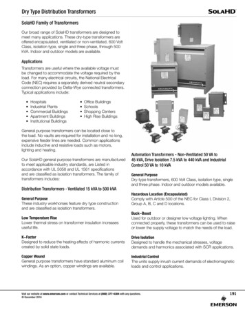
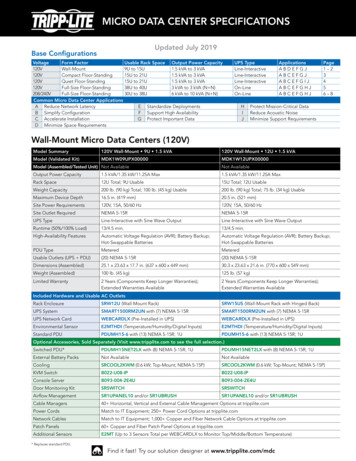
INTRODUCTIONPhysical FeaturesThe Powerware 9170 UPS is available in four cabinet sizes. Figure 1through Figure 6 show the 3-slot and 9-slot configurations and identifybasic Powerware 9170 system features. Six-slot and 12-slot cabinetsare also available; external battery cabinets are available in 6-, 9-, and12-slot sizes.Front PanelDisplayFront CoverFigure 1. Three-Slot Cabinet (Front View)CommunicationSlotsDB-9CommunicationPortPower Outlets(optional)Input PowerCable (optional)Figure 2. Three-Slot Cabinet (Rear View)EATON Powerware 9170 UPS (3–18 kVA) User’s Guide S 164201393 Rev C www.powerware.com5
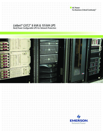
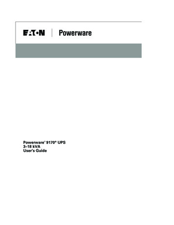
INTRODUCTIONFront Panel DisplayFront CoverCabinet BaseFigure 3. Nine-Slot Cabinet (Front View)6EATON Powerware 9170 UPS (3–18 kVA) User’s Guide S 164201393 Rev C www.powerware.com
INTRODUCTIONDB-9 Communication PortCommunicationSlotsWiring AccessPower Outlets(optional)Input PowerCable (optional)Figure 4. Nine-Slot Cabinet (Rear ExtractionCamsFigure 5. Power Module (ASY-0673 and ASY-0674)Secondary StopReleaseLatch ReleaseFigure 6. Battery Module (ASY-0529)EATON Powerware 9170 UPS (3–18 kVA) User’s Guide S 164201393 Rev C www.powerware.com7
INTRODUCTION8EATON Powerware 9170 UPS (3–18 kVA) User’s Guide S 164201393 Rev C www.powerware.com
Chapter 2Installation SetupThis chapter explains how to set up and install the Powerware 9170 cabinets:S Setup, including clearances and location requirementsS Caster cart installation (for 3- and 6-slot cabinets)S Stabilizer bracket installation (for 12-slot cabinets with non-isolatedoutput)S Rack-mount installation (for 3- and 6-slot cabinets)S Floor anchor kit installationS Moving the cabinetsEquipment ClearancesAll cabinet sizes require the following clearances to allow for servicingand adequate ventilation:S Sides: 15.2 cm (6”)S Top and back: 30.5 cm (12”)S Front: 91.5 cm (36”)If flexible conduit connects the UPS to the service input and loaddistribution panels, you may be able to gain access for servicing bymoving the UPS. If this is the case, you must still leave 30.5 cm (12”)clearance at the back and 15.2 cm (6”) at the sides of the UPS forventilation.NOTE Do not block the ventilation holes on each side and the back of the cabinet.Nine- and 12-slot external battery cabinets may be installed with basestight against the UPS cabinet base and against each other. Six-slotcabinets require 15.2 cm (6”) of separation.EATON Powerware 9170 UPS (3–18 kVA) User’s Guide S 164201393 Rev C www.powerware.com9
INSTALLATION SETUPLocation RequirementsInstall the Powerware 9170 UPS as close as possible to the equipmentor the load distribution panel it will protect. If this distance is more than7.6m (25 ft), transient noise can reappear in the electrical distributionsystem.If a separate external battery cabinet is installed, the battery cabinetsmust be adjacent to the Powerware 9170 UPS. If the batteries will befarther from the cabinet than the standard cables allow, contact yourservice representative or your local distributor for assistance.UPS SetupThe Powerware 9170 UPS is shipped in a carton on a shipping pallet.Power and battery modules are shipped in separate boxes on anotherpallet. Three-slot cabinets and modules are shipped on one pallet. Referto the unpacking instruction sheet (LTS-1724) packed inside the UPSshipping carton.NOTE Verify that all Powerware 9170 UPS power modules are the proper type for the UPScabinet: Split-phase power modules have brown labels; universal (single-phase) powermodules have black labels. Do not mix brown and black modules in the same UPS cabinet.Three- and Six-Slot CabinetsNOTE Do not attempt to lift the cabinet by the module shelves or other convenient edgesor covers.To set up 3- or 6-slot cabinets:101.Place the cabinet in its intended operating location.2.If an optional caster cart is included for cabinet mobility, see“Caster Cart Installation (Three- and Six-Slot Cabinets)” on page 12to mount the cabinet on the cart and stabilize it using the cart footpads.3.Cut the lifting straps or slip them off the cabinet base tabs.4.If an optional floor anchor kit is included for extra stability, see”Floor Anchor Kit Installation” on page 16 to install the floor anchorbrackets.EATON Powerware 9170 UPS (3–18 kVA) User’s Guide S 164201393 Rev C www.powerware.com
INSTALLATION SETUP5.If installing the 3- or 6-slot cabinet in a rack, see ”Rack-MountInstallation (Three- and Six-Slot Cabinets)” on page 14 to install thecabinet in the rack.6.If you are installing an external battery cabinet, continue to “BatteryCabinet Installation” on page 61.If you do not have an external battery cabinet, continue to “UPSStartup” on page 67 for plug-receptacle units. For hardwired units,continue to “UPS with Bypass Electrical Installation” on page 19 or“UPS Electrical Installation” on page 39.Nine- and Twelve-Slot CabinetsCAUTIONDo NOT lower the casters or attempt to move the cabinet with the power or battery modulesinstalled.To set up 9- or 12-slot cabinets:NOTE If you are installing a 12-slot Powerware 9170 UPS with non-isolated output, donot follow this procedure. Proceed to “Stabilizer Bracket Installation (Twelve-Slot CabinetOnly)” on page 13.1.Lower the four cabinet casters (one at each corner of the cabinetbase) by using a 1/2” hex-style socket wrench to turn each boltclockwise.2.With all casters fully extended, carefully roll the cabinet down theramp to its intended operating location.3.Stabilize the cabinet in its operating location by turning the fourcaster bolts counter-clockwise until the cabinet rests on the floor.Place a plastic cap into each bolt access hole.NOTE If the floor is uneven and the cabinet is tilted or unstable, you may need to place athin steel plate under a corner. Do not use the caster bolts to level the cabinet.4.If an optional floor anchor kit is included for extra stability, see”Floor Anchor Kit Installation” on page 16 to install the floor anchorbrackets.EATON Powerware 9170 UPS (3–18 kVA) User’s Guide S 164201393 Rev C www.powerware.com11
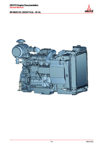
INSTALLATION SETUP5.If installing the 9- or 12-slot cabinet in a rack, follow the installationinstructions with the 9- and 12-slot rack-mount kit.6.If you are installing an external battery cabinet, continue to “BatteryCabinet Installation” on page 61.If you do not have an external battery cabinet, continue to “UPSStartup” on page 67 for plug-receptacle units. For hardwired units,continue to “UPS with Bypass Electrical Installation” on page 19 or“UPS Electrical Installation” on page 39.Caster Cart Installation (Three- and Six-Slot Cabinets)An optional caster cart (ASY-0527) is available for 3- and 6-slot cabinetsfor increased mobility of the UPS (see Figure 7).NOTE The UPS cabinet is heavy (see page 106). This procedure requires two people to liftand position the cabinet onto the caster cart. Lift the cabinet using four lifting straps shippedwith the cabinet; do not attempt to lift the cabinet by the module shelves or other convenientedges or covers.Caster CartFigure 7. Three-Slot Cabinet Being Lowered onto Caster Cart12EATON Powerware 9170 UPS (3–18 kVA) User’s Guide S 164201393 Rev C www.powerware.com
INSTALLATION SETUPTo install the caster cart:1.Place the caster cart (shipped separately from the UPS cabinet)under the cabinet before installing power and battery modules andbefore making connections to the intended power source.The cart requires no bolts or other hardware to fasten it to the UPScabinet. It is shaped to fit securely under the cabinet, ensuringproper alignment after placing the cabinet on the cart.2.Four foot pads under the cart keep the cart from rolling when it is inits intended location. Turn each threaded foot to lower it to thefloor. When the foot is tight against the floor, turn the locknut onthe threaded foot up tight against the bottom of the cart to keep thefoot from rotating.3.If leveling of the UPS is required, use the foot pads to raise a sideor corner before locking them with their locknuts.Stabilizer Bracket Installation (Twelve-Slot Cabinet Only)The 12-slot Powerware 9170 UPS cabinet with non-isolated output isshipped with two stabilizer brackets. These brackets must be attachedto the wall or the floor behind the UPS cabinet. Under all module-loadingconditions, they act as a protective stop to prevent the cabinet fromfalling forward if it is unintentionally pushed away from the wall.Each bracket has holes that enable it to be attached by screws to eitherthe wall or the floor (or both) behind the intended cabinet installation(see Figure 8). The stabilizer brackets are not attached to the cabinetbase itself.To install the stabilizer brackets:1.Select the location for the brackets, approximately 30–41 cm(12–16”) apart, at the floor/wall intersection behind the intendedcabinet location.2.Using the proper type of customer-supplied screws for the intendedmounting surface, attach each bracket as shown in Figure 8. Allscrews must be driven into structural material such as wall studs.3.Roll the UPS cabinet to its intended location. Position the rearsection of the cabinet base under the open ends of the stabilizerbrackets as far as the cabinet will go.EATON Powerware 9170 UPS (3–18 kVA) User’s Guide S 164201393 Rev C www.powerware.com13
INSTALLATION SETUP4.Turn all four caster bolts counter-clockwise until the cabinet restson the floor. Place a plastic cap into each bolt access hole.NOTE If the floor is uneven and the cabinet is tilted or unstable, you may need to place athin steel plate under a corner. Do not use the caster bolts to level the cabinet.Stabi
EATON Powerware 9170 UPS (3-18 kVA) User's Guide S 164201393 Rev C www.powerware.com 5 Physical Features The Powerware 9170 UPS is available in four cabinet sizes. Figure 1 through Figure 6 show the 3-slot and 9-slot configurations and identify basic Powerware 9170 system features. Six-slot and 12-slot cabinets