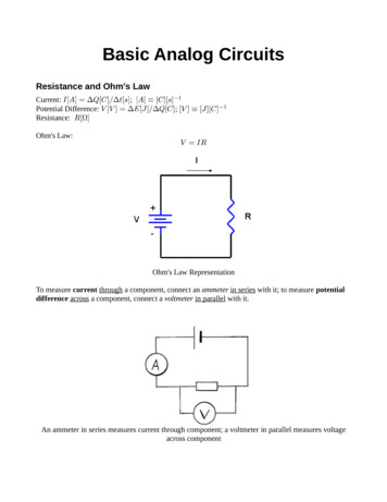
Transcription
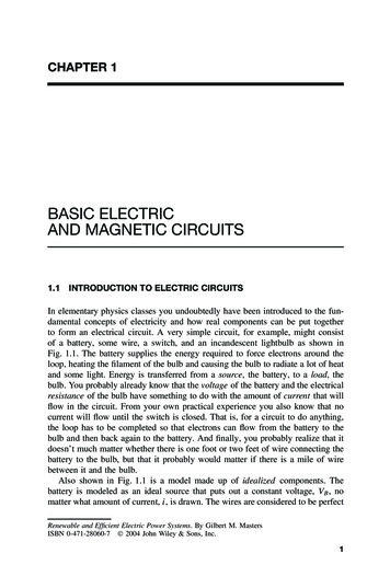
CHAPTER 1BASIC ELECTRICAND MAGNETIC CIRCUITS1.1INTRODUCTION TO ELECTRIC CIRCUITSIn elementary physics classes you undoubtedly have been introduced to the fundamental concepts of electricity and how real components can be put togetherto form an electrical circuit. A very simple circuit, for example, might consistof a battery, some wire, a switch, and an incandescent lightbulb as shown inFig. 1.1. The battery supplies the energy required to force electrons around theloop, heating the filament of the bulb and causing the bulb to radiate a lot of heatand some light. Energy is transferred from a source, the battery, to a load, thebulb. You probably already know that the voltage of the battery and the electricalresistance of the bulb have something to do with the amount of current that willflow in the circuit. From your own practical experience you also know that nocurrent will flow until the switch is closed. That is, for a circuit to do anything,the loop has to be completed so that electrons can flow from the battery to thebulb and then back again to the battery. And finally, you probably realize that itdoesn’t much matter whether there is one foot or two feet of wire connecting thebattery to the bulb, but that it probably would matter if there is a mile of wirebetween it and the bulb.Also shown in Fig. 1.1 is a model made up of idealized components. Thebattery is modeled as an ideal source that puts out a constant voltage, VB , nomatter what amount of current, i, is drawn. The wires are considered to be perfectRenewable and Efficient Electric Power Systems. By Gilbert M. MastersISBN 0-471-28060-7 2004 John Wiley & Sons, Inc.1
2BASIC ELECTRIC AND MAGNETIC CIRCUITS iVB(a)R(b)Figure 1.1 (a) A simple circuit. (b) An idealized representation of the circuit.conductors that offer no resistance to current flow. The switch is assumed to beopen or closed. There is no arcing of current across the gap when the switch isopened, nor is there any bounce to the switch as it makes contact on closure.The lightbulb is modeled as a simple resistor, R, that never changes its value,no matter how hot it becomes or how much current is flowing through it.For most purposes, the idealized model shown in Fig. 1.1b is an adequaterepresentation of the circuit; that is, our prediction of the current that will flowthrough the bulb whenever the switch is closed will be sufficiently accuratethat we can consider the problem solved. There may be times, however, whenthe model is inadequate. The battery voltage, for example, may drop as moreand more current is drawn, or as the battery ages. The lightbulb’s resistancemay change as it heats up, and the filament may have a bit of inductance andcapacitance associated with it as well as resistance so that when the switch isclosed, the current may not jump instantaneously from zero to some final, steadystate value. The wires may be undersized, and some of the power delivered bythe battery may be lost in the wires before it reaches the load. These subtle effectsmay or may not be important, depending on what we are trying to find out andhow accurately we must be able to predict the performance of the circuit. If wedecide they are important, we can always change the model as necessary andthen proceed with the analysis.The point here is simple. The combinations of resistors, capacitors, inductors,voltage sources, current sources, and so forth, that you see in a circuit diagramare merely models of real components that comprise a real circuit, and a certainamount of judgment is required to decide how complicated the model must bebefore sufficiently accurate results can be obtained. For our purposes, we will beusing very simple models in general, leaving many of the complications to moreadvanced textbooks.1.2DEFINITIONS OF KEY ELECTRICAL QUANTITIESWe shall begin by introducing the fundamental electrical quantities that form thebasis for the study of electric circuits.1.2.1ChargeAn atom consists of a positively charged nucleus surrounded by a swarm of negatively charged electrons. The charge associated with one electron has been found
DEFINITIONS OF KEY ELECTRICAL QUANTITIES3to be 1.602 10 19 coulombs; or, stated the other way around, one coulomb canbe defined as the charge on 6.242 1018 electrons. While most of the electronsassociated with an atom are tightly bound to the nucleus, good conductors, likecopper, have free electrons that are sufficiently distant from their nuclei that theirattraction to any particular nucleus is easily overcome. These conduction electrons are free to wander from atom to atom, and their movement constitutes anelectric current.1.2.2CurrentIn a wire, when one coulomb’s worth of charge passes a given spot in onesecond, the current is defined to be one ampere (abbreviated A), named after thenineteenth-century physicist André Marie Ampère. That is, current i is the netrate of flow of charge q past a point, or through an area:i dqdt(1.1)In general, charges can be negative or positive. For example, in a neon light,positive ions move in one direction and negative electrons move in the other.Each contributes to current, and the total current is their sum. By convention, thedirection of current flow is taken to be the direction that positive charges wouldmove, whether or not positive charges happen to be in the picture. Thus, in awire, electrons moving to the right constitute a current that flows to the left, asshown in Fig. 1.2.When charge flows at a steady rate in one direction only, the current is saidto be direct current, or dc. A battery, for example, supplies direct current. Whencharge flows back and forth sinusoidally, it is said to be alternating current, orac. In the United States the ac electricity delivered by the power company hasa frequency of 60 cycles per second, or 60 hertz (abbreviated Hz). Examples ofac and dc are shown in Fig. 1.3.1.2.3Kirchhoff’s Current LawTwo of the most fundamental properties of circuits were established experimentally a century and a half ago by a German professor, Gustav Robert Kirchhoff(1824–1887). The first property, known as Kirchhoff’s current law (abbreviatede i dqdtFigure 1.2 By convention, negative charges moving in one direction constitute a positivecurrent flow in the opposite direction.
4BASIC ELECTRIC AND MAGNETIC CIRCUITSiiTimeTime(a) Direct current(b) Alternating currentFigure 1.3 (a) Steady-state direct current (dc). (b) Alternating current (ac).KCL), states that at every instant of time the sum of the currents flowing into anynode of a circuit must equal the sum of the currents leaving the node, where anode is any spot where two or more wires are joined. This is a very simple, butpowerful concept. It is intuitively obvious once you assert that current is the flowof charge, and that charge is conservative—neither being created nor destroyedas it enters a node. Unless charge somehow builds up at a node, which it doesnot, then the rate at which charge enters a node must equal the rate at whichcharge leaves the node.There are several alternative ways to state Kirchhoff’s current law. The mostcommonly used statement says that the sum of the currents into a node is zeroas shown in Fig. 1.4a, in which case some of those currents must have negativevalues while some have positive values. Equally valid would be the statementthat the sum of the currents leaving a node must be zero as shown in Fig. 1.4b(again some of these currents need to have positive values and some negative).Finally, we could say that the sum of the currents entering a node equals the sumof the currents leaving a node (Fig. 1.4c). These are all equivalent as long as weunderstand what is meant about the direction of current flow when we indicateit with an arrow on a circuit diagram. Current that actually flows in the directionshown by the arrow is given a positive sign. Currents that actually flow in theopposite direction have negative values.nodei1i2(a) i 1 i 2 i 3 0nodei1i3i2(b) i 1 i 2 i 3 0nodei1i3i3i2(c) i 1 i 2 i 3Figure 1.4 Illustrating various ways that Kirchhoff’s current law can be stated. (a) Thesum of the currents into a node equals zero. (b) The sum of the currents leaving the nodeis zero. (c) The sum of the currents entering a node equals the sum of the currents leavingthe node.
DEFINITIONS OF KEY ELECTRICAL QUANTITIES5Note that you can draw current arrows in any direction that you want—thatmuch is arbitrary—but once having drawn the arrows, you must then write Kirchhoff’s current law in a manner that is consistent with your arrows, as has beendone in Fig. 1.4. The algebraic solution to the circuit problem will automatically determine whether or not your arbitrarily determined directions for currentswere correct.Example 1.1 Using Kirchhoff’s Current Law. A node of a circuit is shownwith current direction arrows chosen arbitrarily. Having picked those directions,i1 5 A, i2 3 A, and i3 1 A. Write an expression for Kirchhoff’s currentlaw and solve for i4 .i3i1i2i4Solution. By Kirchhoff’s current law,i1 i2 i3 i4 5 3 1 i4so thati4 1 AThat is, i4 is actually 1 A flowing into the node. Note that i2 , i3 , and i4 are allentering the node, and i1 is the only current that is leaving the node.1.2.4VoltageElectrons won’t flow through a circuit unless they are given some energy tohelp send them on their way. That “push” is measured in volts, where voltage isdefined to be the amount of energy (w, joules) given to a unit of charge,v dwdq(1.2)
6BASIC ELECTRIC AND MAGNETIC CIRCUITSA 12-V battery therefore gives 12 joules of energy to each coulomb of chargethat it stores. Note that the charge does not actually have to move for voltage tohave meaning. Voltage describes the potential for charge to do work.While currents are measured through a circuit component, voltages are measured across components. Thus, for example, it is correct to say that currentthrough a battery is 10 A, while the voltage across that battery is 12 V. Otherways to describe the voltage across a component include whether the voltagerises across the component or drops. Thus, for example, for the simple circuitin Fig. 1.1, there is a voltage rise across the battery and voltage drop acrossthe lightbulb.Voltages are always measured with respect to something. That is, the voltageof the positive terminal of the battery is “so many volts” with respect to thenegative terminal; or, the voltage at a point in a circuit is some amount withrespect to some other point. In Fig. 1.5, current through a resistor results in avoltage drop from point A to point B of VAB volts. VA and VB are the voltagesat each end of the resistor, measured with respect to some other point.The reference point for voltages in a circuit is usually designated with aground symbol. While many circuits are actually grounded—that is, there is apath for current to flow directly into the earth—some are not (such as the battery,wires, switch, and bulb in a flashlight). When a ground symbol is shown on acircuit diagram, you should consider it to be merely a reference point at whichthe voltage is defined to be zero. Figure 1.6 points out how changing the nodelabeled as ground changes the voltages at each node in the circuit, but does notchange the voltage drop across each component.VAB VA VBIThe voltage drop from point A to point B is VAB , where VAB VA VB .Figure 1.5 3V 9V12 V 12 V R1R20V 9V 3V 3 V0V 12 V R1R2 12 V9V 3V 12 V 3V0VR1R2 9V 9 VFigure 1.6 Moving the reference node around (ground) changes the voltages at eachnode, but doesn’t change the voltage drop across each component.
DEFINITIONS OF KEY ELECTRICAL QUANTITIES1.2.57Kirchhoff’s Voltage LawThe second of Kirchhoff’s fundamental laws states that the sum of the voltagesaround any loop of a circuit at any instant is zero. This is known as Kirchhoff’svoltage law (KVL). Just as was the case for Kirchhoff’s current law, there arealternative, but equivalent, ways of stating KVL. We can, for example, say thatthe sum of the voltage rises in any loop equals the sum of the voltage dropsaround the loop. Thus in Fig. 1.6, there is a voltage rise of 12 V across thebattery and a voltage drop of 3 V across R1 and a drop of 9 V across R2 . Noticethat it doesn’t matter which node was labeled ground for this to be true. Just aswas the case with Kirchhoff’s current law, we must be careful about labeling andinterpreting the signs of voltages in a circuit diagram in order to write the properversion of KVL. A plus ( ) sign on a circuit component indicates a referencedirection under the assumption that the potential at that end of the componentis higher than the voltage at the other end. Again, as long as we are consistentin writing Kirchhoff’s voltage law, the algebraic solution for the circuit willautomatically take care of signs.Kirchhoff’s voltage law has a simple mechanical analog in which weight isanalogous to charge and elevation is analogous to voltage. If a weight is raisedfrom one elevation to another, it acquires potential energy equal to the changein elevation times the weight. Similarly, the potential energy given to charge isequal to the amount of charge times the voltage to which it is raised. If youdecide to take a day hike, in which you start and finish the hike at the same spot,you know that no matter what path was taken, when you finish the hike the sumof the increases in elevation has to have been equal to the sum of the decreases inelevation. Similarly, in an electrical circuit, no matter what path is taken, as longas you return to the same node at which you started, KVL provides assurancethat the sum of voltage rises in that loop will equal the sum of the voltage dropsin the loop.1.2.6PowerPower and energy are two terms that are often misused. Energy can be thoughtof as the ability to do work, and it has units such as joules or Btu. Power, onthe other hand, is the rate at which energy is generated or used, and therefore ithas rate units such as joules/s or Btu/h. There is often confusion about the unitsfor electrical power and energy. Electrical power is measured in watts, whichis a rate (1 J/s 1 watt), so electrical energy is watts multiplied by time—forexample, watt-hours. Be careful not to say “watts per hour,” which is incorrect(even though you will see this all too often in newspapers or magazines).When a battery delivers current to a load, power is generated by the battery andis dissipated by the load. We can combine (1.1) and (1.2) to find an expressionfor instantaneous power supplied, or consumed, by a component of a circuit:p dwdw dq · vidtdq dt(1.3)
8BASIC ELECTRIC AND MAGNETIC CIRCUITSEquation (1.3) tells us that the power supplied at any instant by a source, orconsumed by a load, is given by the current through the component times thevoltage across the component. When current is given in amperes, and voltage involts, the units of power are watts (W). Thus, a 12-V battery delivering 10 A toa load is supplying 120 W of power.1.2.7EnergySince power is the rate at which work is being done, and energy is the totalamount of work done, energy is just the integral of power: w p dt(1.4)In an electrical circuit, energy can be expressed in terms of joules (J), where 1watt-second 1 joule. In the electric power industry the units of electrical energyare more often given in watt-hours, or for larger quantities kilowatt-hours (kWh)or megawatt-hours (MWh). Thus, for example, a 100-W computer that is operatedfor 10 hours will consume 1000 Wh, or 1 kWh of energy. A typical householdin the United States uses approximately 750 kWh per month.1.2.8Summary of Principal Electrical QuantitiesThe key electrical quantities already introduced and the relevant relationshipsbetween these quantities are summarized in Table 1.1.Since electrical quantities vary over such a large range of magnitudes, you willoften find yourself working with very small quantities or very large quantities. Forexample, the voltage created by your TV antenna may be measured in millionthsof a volt (microvolts, µV), while the power generated by a large power stationmay be measured in billions of watts, or gigawatts (GW). To describe quantitiesthat may take on such extreme values, it is useful to have a system of prefixes thataccompany the units. The most commonly used prefixes in electrical engineeringare given in Table 1.2.TABLE 1.1Key Electrical Quantities and RelationshipsElectrical rrentVoltagePowerqivpwCAVJ/sWJWhq i dti dq/dtv dw/dqp dw/dtEnergycoulombamperevoltjoule/secondor wattjouleor watt-hourw p dt
9IDEALIZED VOLTAGE AND CURRENT SOURCESTABLE 1.2Common PrefixesSmall QuantitiesLarge QuantitiesQuantityPrefixSymbol10 310 610 910 31061091012kilomegagigaterakMGTIDEALIZED VOLTAGE AND CURRENT SOURCESElectric circuits are made up of a relatively small number of different kinds ofcircuit elements, or components, which can be interconnected in an extraordinarilylarge number of ways. At this point in our discussion, we will concentrate onidealized characteristics of these circuit elements, realizing that real componentsresemble, but do not exactly duplicate, the characteristics that we describe here.1.3.1Ideal Voltage SourceAn ideal voltage source is one that provides a given, known voltage vs , no matterwhat sort of load it is connected to. That is, regardless of the current drawn fromthe ideal voltage source, it will always provide the same voltage. Note that anideal voltage source does not have to deliver a constant voltage; for example, itmay produce a sinusoidally varying voltage—the key is that that voltage is nota function of the amount of current drawn. A symbol for an ideal voltage sourceis shown in Fig. 1.7.A special case of an ideal voltage source is an ideal battery that provides aconstant dc output, as shown in Fig. 1.8. A real battery approximates the idealsource; but as current increases, the output drops somewhat. To account for thatdrop, quite often the model used for a real battery is an ideal voltage source inseries with the internal resistance of the battery.i vs vs v vsLoadFigure 1.7 A constant voltage source delivers vs no matter what current the load draws.The quantity vs can vary with time and still be ideal.
10BASIC ELECTRIC AND MAGNETIC CIRCUITSi vsvsvLoadvi0Figure 1.8 An ideal dc voltage.i isisvLoadv0isiFigure 1.9 The current produced by an ideal current source does not depend on thevoltage across the source.1.3.2Ideal Current SourceAn ideal current source produces a given amount of current is no matter whatload it sees. As shown in Fig. 1.9, a commonly used symbol for such a device iscircle with an arrow indicating the direction of current flow. While a battery is agood approximation to an ideal voltage source, there is nothing quite so familiarthat approximates an ideal current source. Some transistor circuits come close tothis ideal and are often modeled with idealized current sources.1.4ELECTRICAL RESISTANCEFor an ideal resistance element the current through it is directly proportional tothe voltage drop across it, as shown in Fig. 1.10.1.4.1Ohm’s LawThe equation for an ideal resistor is given in (1.5) in which v is in volts, i is inamps, and the constant of proportionality is resistance R measured in ohms ( ).This simple formula is known as Ohm’s law in honor of the German physicist, Georg Ohm, whose original experiments led to this incredibly useful andimportant relationship.v Ri(1.5)
ELECTRICAL RESISTANCE11ivAR v1R0 iB(a)(b)Figure 1.10 (a) An ideal resistor symbol. (b) voltage–current relationship.Notice that voltage v is measured across the resistor. That is, it is the voltage atpoint A with respect to the voltage at point B. When current is in the directionshown, the voltage at A with respect to B is positive, so it is quite common tosay that there is a voltage drop across the resistor.An equivalent relationship for a resistor is given in (1.6), where current isgiven in terms of voltage and the proportionality constant is conductance G withunits of siemens (S). In older literature, the unit of conductance was mhos.i Gv(1.6)By combining Eqs. (1.3) and (1.5), we can easily derive the following equivalent relationships for power dissipated by the resistor:p vi i 2 R v2R(1.7)Example 1.2 Power to an Incandescent Lamp. The current–voltage relationship for an incandescent lamp is nearly linear, so it can quite reasonably bemodeled as a simple resistor. Suppose such a lamp has been designed to consume60 W when it is connected to a 12-V power source. What is the resistance ofthe filament, and what amount of current will flow? If the actual voltage is only11 V, how much energy would it consume over a 100-h period?Solution. From Eq. (1.7),R v2122 2.4 p60and from Ohm’s law,i v/R 12/2.4 5 A
12BASIC ELECTRIC AND MAGNETIC CIRCUITSConnected to an 11-V source, the power consumed would bep v2112 50.4 WR2.4Over a 100-h period, it would consumew pt 50.4 W 100 h 5040 Wh 5.04 kWh1.4.2Resistors in SeriesWe can use Ohm’s law and Kirchhoff’s voltage law to determine the equivalentresistance of resistors wired in series (so the same current flows through eachone) as shown in Fig. 1.11.For Rs to be equivalent to the two series resistors, R1 and R2 , the voltage–current relationships must be the same. That is, for the circuit in Fig. 1.11a,v v1 v2(1.8)v iR1 iR2(1.9)and from Ohm’s law,For the circuit in Fig. 1.11b to be equivalent, the voltage and current must bethe same:v iRs(1.10)By equating Eqs. (1.9) and (1.10), we conclude thatRs R1 R2(1.11)And, in general, for n-resistances in series the equivalent resistance isRs R1 R2 · · · Rnivi R1R2 v1v Rs R 1 R 2v2 (a)Figure 1.11 (b)Rs is equivalent to resistors R1 and R2 in series.(1.12)
ELECTRICAL RESISTANCEv i1iR1R2v iRp i2(a)13R 1R 2R1 R2(b)Figure 1.12 Equivalent resistance of resistors wired in parallel.1.4.3Resistors in ParallelWhen circuit elements are wired together as in Fig. 1.12, so that the same voltageappears across each of them, they are said to be in parallel.To find the equivalent resistance of two resistors in parallel, we can firstincorporate Kirchhoff’s current law followed by Ohm’s law:i i1 i2 vvv R1R2Rp(1.13)so that111 R1R2RporG1 G2 Gp(1.14)Notice that one reason for introducing the concept of conductance is that the conductance of a parallel combination of n resistors is just the sum of the individualconductances.For two resistors in parallel, the equivalent resistance can be found fromEq. (1.14) to beR1 R2Rp (1.15)R1 R2Notice that when R1 and R2 are of equal value, the resistance of the parallelcombination is just one-half that of either one. Also, you might notice that theparallel combination of two resistors always has a lower resistance than eitherone of those resistors.Example 1.3 Analyzing a Resistive Circuit. Find the equivalent resistance ofthe following network.
14BASIC ELECTRIC AND MAGNETIC CIRCUITS800 Ω800 Ω2 kΩ400 Ω800 Ω800 Ω800 ΩSolution. While this circuit may look complicated, you can actually work it outin your head. The parallel combination of the two 800- resistors on the rightend is 400 , leaving the following equivalent:800 Ω800 Ω400 Ω2 kΩ400 Ω800 ΩThe three resistors on the right end are in series so they are equivalent to asingle resistor of 2 k ( 800 400 800 ). The network now lookslike the following:800 Ω2 kΩ2 kΩ400 ΩThe two 2-kW resistors combine to 1 k , which is in series with the 800- and 400- resistors. The total resistance of the network is thus 800 1 k 400 2.2 k .
ELECTRICAL RESISTANCE1.4.415The Voltage DividerA voltage divider is a deceptively simple, but surprisingly useful and importantcircuit. It is our first example of a two-port network. Two-port networks have apair of input wires and a pair of output wires, as shown in Fig. 1.13.The analysis of a voltage divider is a straightforward extension of Ohm’s lawand what we have learned about resistors in series.As shown in Fig. 1.14, when a voltage source is connected to the voltagedivider, an amount of current flows equal toi vinR1 R2(1.16)Since vout iR2 , we can write the following voltage-divider equation: vout vinR2R1 R2 (1.17)Equation (1.17) is so useful that it is well worth committing to memory.R1 vinvinTwo-portnetworkvoutvoutR2 Figure 1.13A voltage divider is an example of a two-port network.R1vini voutR2 Figure 1.14 A voltage divider connected to an ideal voltage source.Example 1.4 Analyzing a Battery as a Voltage Divider. Suppose an automobile battery is modeled as an ideal 12-V source in series with a 0.1- internal resistance.
16BASIC ELECTRIC AND MAGNETIC CIRCUITSa. What would the battery output voltage drop to when 10 A is delivered?b. What would be the output voltage when the battery is connected to a1- load? Ri 0.1 Ω Battery Load10 A 12 VBatteryVout LoadSolutiona. With the battery delivering 10 A, the output voltage drops toVout VB I Ri 12 10 0.1 11 Vb. Connected to a 1- load, the circuit can be modeled as shown below:0.1 ΩVout 1Ω12 VWe can find Vout from the voltage divider relationship, (1.17): vout vin1.4.5R2R1 R2 1.0 120.1 1.0 10.91 VWire ResistanceIn many circumstances connecting wire is treated as if it were perfect—that is,as if it had no resistance—so there is no voltage drop in those wires. In circuits
ELECTRICAL RESISTANCE17delivering a fair amount of power, however, that assumption may lead to seriouserrors. Stated another way, an important part of the design of power circuits ischoosing heavy enough wire to transmit that power without excessive losses. Ifconnecting wire is too small, power is wasted and, in extreme cases, conductorscan get hot enough to cause a fire hazard.The resistance of wire depends primarily on its length, diameter, and the material of which it is made. Equation (1.18) describes the fundamental relationshipfor resistance ( ):l(1.18)R ρAwhere ρ is the resistivity of the material, l is the wire length, and A is the wirecross-sectional area.With l in meters (m) and A in m2 , units for resistivity ρ in the SI system are -m (in these units copper has ρ 1.724 10 8 -m). The units often used inthe United States, however, are tricky (as usual) and are based on areas expressedin circular mils. One circular mil is the area of a circle with diameter 0.001 in.(1 mil 0.001 in.). So how can we determine the cross-sectional area of a wire(in circular mils) with diameter d (mils)? That is the same as asking how many1-mil-diameter circles can fit into a circle of diameter d mils.π 2d sq milA π 4 d 2 cmil2· 1 sq mil/cmil4(1.19)Example 1.5 From mils to Ohms. The resistivity of annealed copper at 20 Cis 10.37 ohm-circular-mils/foot. What is the resistance of 100 ft of wire withdiameter 80.8 mils (0.0808 in.)?SolutionR ρl100 ft 10.37 cmil/ft · 0.1588 A(80.8)2 cmilElectrical resistance of wire also depends somewhat on temperature (as temperature increases, greater molecular activity interferes with the smooth flow ofelectrons, thereby increasing resistance). There is also a phenomenon, called theskin effect, which causes wire resistance to increase with frequency. At higherfrequencies, the inherent inductance at the core of the conductor causes currentto flow less easily in the center of the wire than at the outer edge of conductor,thereby increasing the average resistance of the entire conductor. At 60 Hz, formodest loads (not utility power), the skin effect is insignificant. As to materials,copper is preferred, but aluminum, being cheaper, is sometimes used by professionals, but never in home wiring systems. Aluminum under pressure slowly
18BASIC ELECTRIC AND MAGNETIC CIRCUITSTABLE 1.3Characteristics of Copper WireWire Gage(AWG No.)Diameter(inches)AreacmilsOhms per100 ftaMax 15880.252519516512595705540302015adc, at 68 F.deforms, which eventually loosens connections. That, coupled with the highresistivity oxide that forms over exposed aluminum, can cause high enough I 2 Rlosses to pose a fire hazard.Wire size in the United States with diameter less than about 0.5 in. is specifiedby its American Wire Gage (AWG) number. The AWG numbers are based onwire resistance, which means that larger AWG numbers have higher resistanceand hence smaller diameter. Conversely, smaller gage wire has larger diameterand, consequently, lower resistance. Ordinary house wiring is usually No. 12AWG, which is roughly the diameter of the lead in an ordinary pencil. Thelargest wire designated with an AWG number is 0000, which is usually written4/0, with a diameter of 0.460 in. For heavier wire, which is usually stranded(made up of many individual wires bundled together), the size is specified in theUnited States in thousands of circular mills (kcmil). For example, 1000-kcmilstranded copper wire for utility transmission lines is 1.15 in. in diameter andhas a resistance of 0.076 ohms per mile. In countries using the metric system,wire size is simply specified by its diameter in millimeters. Table 1.3 gives somevalues of wire resistance, in ohms per 100 feet, for various gages of copper wireat 68 F. Also given is the maximum allowable current for copper wire clad inthe most common insulation.Example 1.6 Wire Losses. Suppose an ideal 12-V battery is delivering currentto a 12-V, 100-W incandescent lightbulb. The battery is 50 ft from the bulb, andNo. 14 copper wire is used. Find the power lost in the wires and the powerdelivered to the bulb.
ELECTRICAL RESISTANCE19Solution. The resistance, Rb , of a bulb designed to use 100 W when it is suppliedwith 12 V can be found from (1.7):P v2RsoRb 122v2 1.4
4 BASIC ELECTRIC AND MAGNETIC CIRCUITS Time (a) Direct current (b) Alternating current Time i i Figure 1.3 (a) Steady-state direct current (dc). (b) Alternating current (ac). KCL), states that at every instant of time the sum of the currents flowing into any node of a circuit must equal the sum of the currents leaving the node,wherea node is any spot where two or more wires are joined.