Transcription
092769 RevAAquaRite S3 Series Pool Chlorinator and Automation Control\.Owner’s ManualContentsBefore You Begin.2Mounting the Equipment.7Plumbing.8Electrical.,,.9Preparing Water.17Configuration.20Operation.22Remote d Industries400 Connell Drive, Suite 6100Berkeley Heights, NJ 07922Phone: (908) 355-7995www.hayward.comUSE ONLY HAYWARD GENUINE REPLACEMENT PARTS
IMPORTANT SAFETY INSTRUCTIONSWhen using this electrical equipment, basic safety precautions should always be followed, includingthe following: READ AND FOLLOW ALL INSTRUCTIONS Use Copper Conductors Only Disconnect all AC power during installation. Warning - To reduce the risk of injury, do not permit children to use this product unless they areclosely supervised at all times. Hayward salt systems are designed, tested and sold as systems and are certified by severalagencies around the globe --- with each component of the systems meeting all required certifications and attendant legal requirements. The use of an untested, uncertified generic cells (orgeneric circuit boards) with Genuine Hayward salt chlorination products could lead to prematureproduct failure. Pursuant to the terms and conditions of any applicable Warranty, the use of a non-genuineHayward replacement salt chlorination cell on any Hayward automation or chlorination productwill void any Warranty. A green colored terminal is located inside the wiring compartment. To reduce the risk of electricshock, this terminal must be connected to the grounding means provided in the electric supplyservice panel with a continuous copper wire equivalent in size to the circuit conductors supplyingthe equipment. All field installed metal components such as rails, ladders, drains, or other similar hardwarewithin 3 meters of the pool, spa or hot tub shall be bonded to the equipment grounding bus withcopper conductors not smaller than 8 AWG US / 6 AWG Canada. NOTICE TO USERS: This control product is to be used only in accordance with the directions ofthis label. It is an offense under the Pest Control Products Act to use a control product underunsafe conditions.SAVE THESE INSTRUCTIONS1USE ONLY HAYWARD GENUINE REPLACEMENT PARTS
FCC StatementThis device complies with part 15 of the FCC rules. Operation is subject to the following two conditions:(1) This device may not cause harmful interference, and (2) this device must accept any interferencereceived, including interference that may cause undesired operation.Changes or modifications not expressly approved by Hayward could void the user’s authority to operate this equipment.NOTE: This equipment has been tested and found to comply with the limits for a Class B digital device,pursuant to Part 15 of the FCC Rules. These limits are designed to provide reasonable protectionagainst harmful interference in a residential installation. This equipment generates, uses and canradiate radio frequency energy and, if not installed and used in accordance with the instructions, maycause harmful interference to radio communications. However, there is no guarantee that interferencewill not occur in a particular installation. If this equipment does cause harmful interference to radioor television reception, which can be determined by turning the equipment off and on, the user isencouraged to try to correct the interference by one or more of the following measures:-- Reorient or relocate the receiving antenna.-- Increase the separation between the equipment and receiver.-- Connect the equipment into an outlet on a circuit different from that to which the receiver isconnected.-- Consult the dealer or an experienced radio / TV technician for help.Industry Canada StatementThis Class B digital apparatus complies with Canadian ICES-003.Cet appareil numérique de la classe B est conforme à la norme NMB-003 du Canada.The term “IC” before the certification / registration number only signifies that the Industry Canadatechnical specifications were met.Before you BeginThe AquaRite S3 is an automatic chlorine generation system with control functions for pool or spasanitization. Chlorine generation requires a concentration of salt (sodium chloride) in the pool water.The unique design of the AquaRite S3 allows for a broad range of salt concentration ensuring efficientchlorine production regardless of salt level. The AquaRite S3 automatically sanitizes your pool by converting the salt into free chlorine which kills bacteria and algae in the pool. Chlorine will revert backto sodium chloride after killing bacteria. These reactions will continuously recycle virtually eliminatingthe need to add sanitizing chemicals to your pool. The only time you may need to add more salt tothe pool is when water is replenished due to backwashing, draining, or splashing (not evaporation).The AquaRite S3 also provides control functions adding convenience to pool and spa management.Built in functions include variable speed filter pump control, single speed filter pump control (requiresSmart Relay), heater control, pool cover detection, and more.2USE ONLY HAYWARD GENUINE REPLACEMENT PARTS
The AquaRite S3 is offered in three models with the AQRS340 designed to handle the purificationneeds of most residential swimming pools up to 40,000 gallons (150,000 liters), or most commercialpools up to 25,000 gallons (95,000 liters). Check local codes for other restrictions. The actual amountof chlorination required to properly sanitize a pool varies due to bather load, rainfall, temperature,and the pool’s cleanliness.Use the proper AquaRite S3 model for your pool (installation and mounting requirements are thesame for all models):AQRS340 - for pools up to 40,000 gallonsAQRS325 - for pools up to 25,000 gallonsAQRS315 - for pools up to 15,000 gallonsWhat’s IncludedBefore attempting to install the AquaRite S3 system, check that the following components have beenincluded in the package: AquaRite S3 Electronics UnitFlow SwitchElectrolytic CellWhat’s NOT IncludedSome of the additional items that you may need to complete an installation include: Wire/conduit for 115 VAC or 230 VAC connection from the main panel to AquaRite S3Wire/conduit for filter pumpWire for remote heater controlHayward Smart Relay - required for single speed filter pump controlTemperature sensors (water sensor necessary for heater control, air sensor needed for recirculation freeze control)Mounting hardware (screws, bolts, etc.) for mounting AquaRite S3Tools and PVC glue for installing the TurboCell and flow switchNOTE: Hayward does not recommend using the AquaRite S3 to generate bromine.NOTE: Before installing this product as part of a saline water purification system in a pool or spa using natural stone for coping or for immediately adjacent patios/decking, a qualified stone installationspecialist should be consulted regarding the appropriate type, installation, sealant (if any) and maintenance of stone used around a saline pool with an electronic chlorine generator in your particularlocation and circumstances.NOTE: The use of dry acid (sodium bisulfate) to adjust pool pH is discouraged especially in aridregions where pool water is subject to excessive evaporation and is not commonly diluted with freshwater. Dry acid can cause a buildup of by-products that can damage your chlorinator cell.3USE ONLY HAYWARD GENUINE REPLACEMENT PARTS
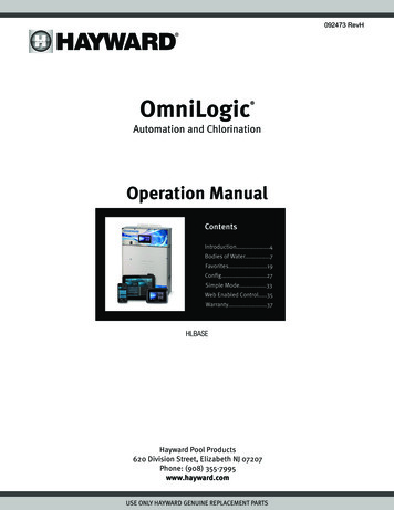
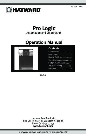
The functions and features described in this manual assume that the AquaRite S3 is using the latest firmware version available from Hayward. For the AquaRite S3, a USB port is used for firmwareupgrades. The latest firmware can be found on the AquaRite S3’s product page on the Haywardwebsite. For instructions on how to upgrade firmware, refer to page 21.Although the AquaRite S3 is easy to use, it is important to completely read through this manualbefore attempting to install, configure and operate the unit.FeaturesThe AquaRite S3 offers the following features: can generate chlorine using a broad range of salt concentrations from 1200 PPM to 8000 PPMcan control and schedule a Hayward Variable Speed (VSP) pump using the internal RS-485connection, a Pentair VSP using a Hayward HLPMPCONV converter (sold separately) or a singlespeed pump using a Hayward Smart Relay (sold separately)can control a gas heater, heat pump or any other heater that uses a low voltage on/off remoteconnection (requires Hayward water temperature sensor sold separately)inputs for water and air temperature sensors (temperature sensors sold separately)connection for flow switch used to detect water flowconnection for pool cover detection (lowers chlorine production when the pool is covered)can be powered by either 115 or 230 VACoffers recirculation freeze control which turns on the filter pump automatically to prevent freezing (requires Hayward air temperature sensor sold separately)Display ConnectorVSP or Smart RelayUSB for firmware upgradesTemperature and PoolCover SensorsHeaterInput PowerConnectorTurboCellFlow Switch4USE ONLY HAYWARD GENUINE REPLACEMENT PARTS
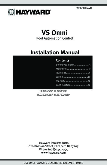
Front Panel RemovalDANGER of Death, Injury or Property Damage if procedure not followed. Dead front removalis required for this installation. Power to the AquaRite S3 panel MUST be shut off before the deadfront is removed. This means a complete shutdown of power to the entire AquaRite S3 panel.Pull the display away fromthe panel by grasping itwith your hand (no toolsrequired). Then, removethe 3 screws and pull theplastic panel away fromthe enclosure. It is notnecessary to disconnectthe display wiring.Removethree screwsInstallation StepsDetails on each installation step are presented on the following pages:1. Mounting the equipment (page 7)AquaRite S3 main unitOptional Temperature sensors2. Plumbing (page 8)TurboCellFlow Switch3. Electrical Wiring (page 9)High VoltageLow voltage wiring (Smart Relay, VSP, heater, sensors, heater, flow switch and TurboCell)4. Prepare the pool water (page 17)General Water ChemistrySalt5. System Startup (page 19)ConfigurationOperation5USE ONLY HAYWARD GENUINE REPLACEMENT PARTS
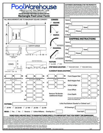
6USE ONLY HAYWARD GENUINE REPLACEMENT PARTSVariableSpeed PumpPower to VSPdirectly fromelectrical panelComm.to VSPFROMPOOLFilterPower to Heat Pumpdirectly fromelectrical panelPower to heat pumpdirectly from electrical panel120 or 240 VACfromMain PanelHeaterAquaRite S3FlowSwitchTurboCellTOPOOLComm. to Smart Relay (15’)Power to Smart Relay(wired in parallel withAquaRite S3)OFFLINE:ON/OFFRELAYREMOTE(Optional)Smart RelayAir Temperature SensorWater Temperature SensorPool Cover SensorTo Single Speed Pump(if no VSP is used)
Mounting the EquipmentAquaRite S3 EnclosureThe AquaRite S3 is contained in a raintight enclosure that is suitable for outdoor mounting. Thecontrol must be mounted a minimum of 6 ft. (2 meters) horizontal distance from the pool/spa (ormore, if local codes require). The AquaRite S3 is designed to mount vertically on a flat surface withthe knockouts facing downward. Because the enclosure is vented (disperses heat from inside thebox), it is important not to block the four sides of the control. Do not mount the AquaRite S3 inside apanel or tightly enclosed area. Plugs are supplied to seal any unused knockouts.When selecting a mounting location, note that the standard cables supplied with the included flowswitch and TurboCell, as well as optional accessories like Hayward temperature sensors, are all 15ft. (5m) long. Try to mount the AquaRite S3 at a height/location where the screen and keypad canbe easily used. Select the proper mounting hardware given the size and weight of the unit. TheAquaRite S3 mounting brackets require a total of 4 mounting screws/bolts to fasten the AquaRite S3to the mounting surface.Temperature Sensors (sold separately)If using the heater function or the recirculation freeze protection function, the AquaRite S3 will requirethe use of Hayward temperature sensors. Refer to the following information for mounting instructions.Water Sensor (required for heater control)This sensor is used to measure the pool/spa temperature and is installed in the filtration plumbingafter the filter but before either the solar or conventionally fueled heaters—refer to the plumbingoverview diagram.1.Drill a 3/8” (10mm) diameter hole in the PVC piping and remove all chips and burrs.2.Insert sensor until O-ring collar sits flush on the hole.3. Position hose clamp over the sensor and gently tighten until O-ring makes an adequate seal.Do not overtighten.Air Sensor (required for recirc freeze protection)Mount the air sensor outdoors to a surface with low thermal conductivity. IMPORTANT: The air sensormust not be mounted in direct sunlight.7USE ONLY HAYWARD GENUINE REPLACEMENT PARTS
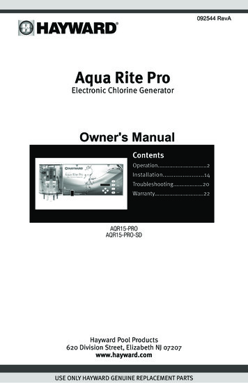
PlumbingEnsure that the AquaRite S3 installation does not constitute a cross connection with the local potablewater supply. Consult local plumbing codes.The AquaRite S3 is packaged with a TurboCell, flow switch and cell unions.The flow switch and cell should be plumbed in the return line to the pool/spa. The preferred installation is after (downstream) all the pool equipment (filter, heater, solar, etc.). The electrolytic cell andflow switch tee fitting are designed to be plumbed into 2” (51mm) PVC pipe. Adapters (not included)can be used for systems with 1½” (38 mm) plumbing.For proper plumbing, refer to the overview diagram on page 6. Alternate configuration #1 shows theflow switch can also be in front of the cell. Configurations #2 and #3 allow for chlorination of boththe pool and spa during spa spillover operation, but prevent overchlorination of the spa during “spaonly” operation. Never use configuration #4.Flow Switch:IMPORTANT: There must be at least a 12” (25cm) straight pipe run before(upstream) the flow switch. If the switch is plumbed after the cell, the cell canby counted as the 12” (25cm) of straight pipe. To ensure proper operation,verify that the arrow on the flow switch (located on top of gray hex) points inthe direction of water flow.Electrolytic Cell:Install using the unions provided. Tighten unions BY HAND for a watertightseal. For pool/spa combination systems with spillover, use configurations #2or #3 above to allow chlorination of both the pool and spa during spillover butpreventing overchlorination when operating the spa CellFlowSwitchPoolSpa4FlowSwitchSpaPool8USE ONLY HAYWARD GENUINE REPLACEMENT PARTS
ElectricalThe AquaRite S3 requires both high and low voltage connections. A high voltage connection will bemade to the AquaRite S3 to power the unit. Low voltage connections will be made to sensors, VSPwiring, optional Smart Relay, heater wiring and more. Enclosure knockouts are provided for high voltage wiring. A low voltage channel inside the enclosure will ensure a separation of wiring and organizethe low voltage wiring coming into the AquaRite S3 enclosure. Refer to the diagram below for thelocation of knockouts and internal wiring paths. Always: Ensure that power is disconnected prior to performing any wiringFollow all local and NEC (CEC if applicable) codesUse copper conductors onlyAlways remove power to the AquaRite S3 before removing the front panelInside ViewHigh Voltage knockoutsLow Voltage WiringChannelBottom ViewHigh Voltage knockoutsLow Voltage WiringChannel9USE ONLY HAYWARD GENUINE REPLACEMENT PARTS
High Voltage WiringInput PowerIf the AquaRite S3 will be controlling a VSP or single speed pump using a Smart Relay, it must bepowered continuously. A schedule will be created for the pump and the AquaRite S3 will generatechlorine only when the pump is running. If the AquaRite S3 will not be controlling the filter pump, itshould be wired to the load side of the pump timer or in parallel with the filter pump. This will ensurethat the AquaRite S3 will power up with the pump and only generate chlorine when the pump is running. If not wired in that manner, the flow switch will enable/disable the chlorinator function.Power ConnectionThe AquaRite S3 can be powered by 115 VAC (2A) or 230 (1A) VAC. There is no need to manuallyselect or use different input terminals, the AquaRite S3 will automatically detect the input voltage. Awiring harness is included and will plug into the input power connector shown below. Wire nuts aresupplied for connecting the harness to input power. Wire the harness according to the diagram below.Connect the ground wire to one of the green ground screws as shown.For Canadian installations, the AquaRite S3 shall be connected to a circuit protected by a class Aground fault interrupter.Groundfor 115 VAC use black (L1) and gray (N)orfor 230 VAC use black (L1) and gray (L2)10USE ONLY HAYWARD GENUINE REPLACEMENT PARTS
If the AquaRite S3 is controlling a single speed filter pump using a Smart RelayUse this wiring method when the AquaRite S3 is controlling a single speed filter pump with a SmartRelay. The Smart Relay and the AquaRite S3 are continuously powered as shown. The AquaRite S3will control the Smart Relay’s function using the low voltage communication wiring. The diagramsbelow show wiring for 115 VAC and 230 VAC.Electrical PanelPowering AquaRite S3 andSmart Relay with 115 VAC115 VACSingle Speed PumpNeutralLine 1 outNot UsedNot UsedBlack/WhiteBlackGrayLine 1 in115 VAC Smart RelayORElectrical PanelPowering AquaRite S3 andSmart Relay with 230 VAC230 VACSingle Speed PumpLine 2 inLine 1 outLine 1 inRed/WhiteRedBlack/WhiteBlackGrayLine 2 out230 VAC Smart Relay11USE ONLY HAYWARD GENUINE REPLACEMENT PARTS
If the AquaRite S3 is controlling a VSPUse this wiring method when the AquaRite S3 is controlling a Hayward VSP. For Pentair VSPs, aHayward HLPMPCONV converter (sold separately) must be used. The pump and the AquaRite S3are continuously powered as shown. The AquaRite S3 will control the pump’s function using the lowvoltage communication wiring.Electrical PanelBoth the VSP and the AquaRiteS3 are powered continuously bythe electrical panelVariable Speed PumpIf the AquaRite S3 is NOT controlling the filter pumpUse this wiring method when the AquaRite S3 is not controlling the pump. Power from the filter pumptimer or source will power the pump and AquaRite S3 at the same time.Timeclock or SwitchThe filter pump and AquaRite S3 areturned on and off togetherSingle Speed Pump12USE ONLY HAYWARD GENUINE REPLACEMENT PARTS
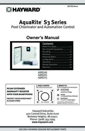
Low Voltage WiringNOTE: There is a low voltage channel on the right side of the AquaRite S3 enclosure shown on page9. All low voltage wiring that enters/exits the enclosure must run through this channel. There is afoam gasket included with the AquaRite S3 that should be used to seal the channels’s exit after wiring is complete. Do not run low voltage wiring through a knockout or with any high voltage wiring.Smart Relay WiringSmart Relays rely on communication from the AquaRite S3. A Smart Relay comes with a 15ft 4conductor cable and is wired to the RS-485 connector. Wire the cable as shown in the diagram. Afterconnecting the wires to the connector, run the communication cable through the low voltage WiringChannel as shown.To ease wiring, the connector can be lifted off the onboard pins. Connect the Smart Relay communication wires to their proper screw terminals, then push the connector back onto the pins. For bestresults, strip back leads 1/8” before inserting into the screw terminals.GreenWhiteBlackRedSmart Relay ConnectionHayward Variable Speed Pump (VSP) WiringThe Hayward TriStar 950, TriStar 900, Super Pump 700 and MaxFlo 500 pumps wire directly to theRS-485 connector and will be fully controlled by the AquaRite S3 (schedules and speeds). Refer tothe VSP Communication Wiring table and diagrams on the following page for VSP communicationwiring instructions. For Pentair VSP models, use a Hayward HLPMPCONV converter (sold separately).Refer to the HLPMPCONV instructions for wiring information. After wiring, run the communicationcable through the low voltage Wiring Channel (same as Smart Relay above).To ease wiring, the connector can be lifted off the onboard pins. Connect the VSP communicationwires to their proper screw terminals, then push the connector back onto the pins. For best results,strip back leads 1/8” before inserting into the screw terminals.13USE ONLY HAYWARD GENUINE REPLACEMENT PARTS
14USE ONLY HAYWARD GENUINE REPLACEMENT PARTS1A or 2B or 34231 2 34 US8754321WALL MOUNT DISPLAY6Input PowerTristar VS 950BLUMOTORRED(after Jan 2019)Input PowerTristar VS 9501234B COMBCOMAbare wire(before Jan 2019)Input Powerbare wireFor pump models with dip switches,set all switches to OFF position (asshown). Remove the display cable.Use the spare connector taped to thedisplay cable for the communicationcable connection.* Disconnect onboard display and set all dip switches to OFF position.*MaxFlo VS 500Pump VS700*Super*TriStar VS 900COM or 483472TriStar VS 950(before Jan 2019)*TriStar VS 950(after Jan 2019)Pump Conn.S3 Conn.Pump ModelVSP CommunicationWiring Table3 conductorcommunication cable43212341TriStar VS 900, Super Pump VS 700, MaxFlo VS 500
Heater ControlThe AquaRite S3 provides a set of low voltage dry contacts that can be connected to most gas heaters or heat pumps with 24V control circuits. Manuals supplied with most heaters include specificwiring instructions for connecting the heater to an external control (usually identified as “2-wire”remote control). For millivolt or line voltage heaters, contact Hayward Technical support.Heater Connection2-Wire RemoteControl wiring1.2.3.Wire heater to 120/240V power source per the instructions in the heater manual. The AquaRiteS3 does NOT control the power going to the heater.Wire the AquaRite S3 heater output (shown above) to the heater’s remote control connection(refer to heater manufacturer’s manual). Many internal parts of the heater can get very hot--seethe heater manufacturer’s recommendations on the minimum temperature rating for wires. If noguidance is given, use 105 C rated wire.Refer to the heater manual but it’s very likely that the heater’s ON/OFF switch must be set to ONand the thermostat set to the maximum (hottest) setting.SensorsTemperature SensorsThe AquaRite S3 utilizes Hayward 10K ohm thermistor type sensors for measurement of pool and airtemperature. The sensors come with a 15 ft cable. If a longer cable is required, contact the HaywardTechnical support for information on suitable cable types and splices.Temperature sensors are wired to the 6 position connector shown on page 4 and below. To easewiring, the connector can be lifted off the onboard pins. Connect the temperature sensors to theirproper screw terminals, then push the connector back onto the pins. For best results, strip back leads1/8” before inserting into the screw terminals.15USE ONLY HAYWARD GENUINE REPLACEMENT PARTS
Pool Cover SensorIf the pool has a motorized cover, the AquaRite S3 can automatically scale back operational limits(both chlorination setpoint and pump speed) to ensure overchlorination doesn’t occur. The pool coversensor must use a normally open switch that connects to the pool cover terminals shown below.Refer to the pool cover manufacturer’s literature to determine compatibility.POOL COVERAIRPOOLFinal StepsWith the previous wiring completed, locate the precut removable foam gasket that can be used toseal the low voltage exit. Wrap it around the low voltage wiring at the exit of the enclosure (shownbelow). Work the gasket into the exit slot until it is fully sealed then re-install the panel and display.Foam GasketFlow SwitchThe flow switch cable plugs into the flow switch connector on the bottom of the AquaRite S3’s enclosure shown on page 4. Ensure that the connector latch “snaps” into place.TurboCellThe TurboCell should be plugged in AFTER the AquaRite S3 cover panel is installed. Refer to page 4for the location of the chlorinator cell connector.16USE ONLY HAYWARD GENUINE REPLACEMENT PARTS
Preparing Pool/Spa WaterSalt ChlorinationThe AquaRite S3 automatically converts salt into free chlorine which kills bacteria and algae in thepool/spa. Chlorine will revert back to sodium chloride after killing bacteria. These reactions willcontinuously recycle, virtually eliminating the need to add sanitizing chemicals to your pool/spa.The only time you may need to add more salt to the pool/spa is when water is replenished due tobackwashing, draining, or splashing (not evaporation). The actual amount of chlorination required toproperly sanitize a pool varies due to bather load, rainfall, temperature, and the pool’s cleanliness.Water ChemistryThis table summarizes the levels that are recommended by the Association of Pool and SpaProfessionals (APSP). The salt level listed belowis a recommendation which allows for effectivechlorine generation but generally stays belowthe level of human taste. If running higher levels,note that swimmers may taste the presence ofsalt.Saturation indexThe saturation index (Si) relates to the calciumand alkalinity in the water and is an indicator ofthe pool water “balance”. Your water is properlybalanced if the Si is 0 0.2. If the Si is below-0.2, the water is corrosive and plaster pool walls will be dissolved into the water. If the Si is above 0.2, scaling and staining will occur. Use the chart below to determine the saturation index.Si pH Ti Ci Ai - TDS C FTiHardnessCalciumCiTotalalkalinityAiTotal .44Use: Measure the pH of the pool water, the temperature, water hardness, total alkalinity,and total dissolved solids. Use the table above to determine Ti, Ci, Ai, and TDS in theformula shown above. If the Si is equal to 0.2 or more, stains may appear. If the Si isequal to -0.2 or less, corrosion or deterioration may occur.Corrosion-0.20.2StainOk17USE ONLY HAYWARD GENUINE REPLACEMENT PARTS
The pool’s chemistry must be balanced BEFORE activating the AquaRite S3’s. NOTE: If the pool doesnot have new water, add metal remover and non-copper based algaecide to the pool, per manufacturer’s instructions. This ensures a quick, troublefree transfer to the AquaRite S3 system.SaltUse the chart on the following page to determine how much salt in pounds or (Kgs) should be addedto reach the recommended levels. Use the Pool Sizing Formula below (measurements are in feet/gallons and meters/liters) if pool size is unknown.The operating salt level is between 1200 PPM - 8000 PPM (parts per million) with 3200 PPM beingoptimal. If the water’s salt concentration decreases, the AquaRite S3 will continue to operate downto 800 PPM in an alarmed state before shutting down.Before adding any salt, first test the pool’s salt level. Chlorine added to a pool over time can producesalt so this is especially important for retrofit installation to older pools. If the level is low, determinethe number of gallons in the pool and add salt according to the chart below. The salt in your pool/spa is constantly recycled and the loss of salt throughout the swimming season should be minimal.This loss is due primarily to the addition of water because of splashing, backwashing, or draining(because of rain). Salt is not lost due to evaporation.Type of Salt to UseIt is important to use only sodium chloride (NaCl) salt that is greater than 99.0% pure. This can befound at most pool stores in 40-80 lb. bags labeled “for use in swimming pools”. Alternatively, usecommon food quality or water softener salt that is at least 99.0% pure. It is also acceptable to usewater conditioning salt pellets, however, it will take longer for them to dissolve. Do not use rock salt,or salt with more than 1% of yellow prussiate of soda, salt with anti-caking additives, or iodized salt.How to Add SaltFor new plaster pools, wait 10-14 days before adding salt to allow the plaster to cure. Turn thecirculating pump on and add salt directly into the pool. Brush the salt around to speed up the dissolving process—do not allow salt to pile up on the bottom of the pool. Run the filter pump for 24hours with the suction coming from the main drain (use pool vacuum if there is no main drain) toallow the salt to evenly disperse throughout the pool. The salt display may take 24 hours to respondto the change in salt concentration.Always check stabilizer (cyanuric acid), when checking salt. These levels will most likely declinetogether. Use the chart on the following page to determine how much stabilizer must be added toraise the level to 40 ppm.18USE ONLY HAYWARD GENUINE REPLACEMENT PARTS
System StartupBefore StartupBefore starting the AquaRite S3 for the first time, be sure that the following items have been completed:1.2.3.4.Pool/spa chemicals are within the recommended levels according to the table on page 17.Pool/spa salt level is between 1200 PPM - 8000 PPM.All wiring is performed according to NEC and local codes.The AquaRite S3 is properly grounded.19USE ONLY HAYWARD GENUINE REPLACEMENT PARTS
ConfigurationWhen all input and pool related wiring is complete, replace and secure the front panel. The AquaRiteS3 can now be powered on for the first time. Apply power and wait for the AquaRite S3 to completelystart. Because this is the first time that the AquaRite S3 has been powered on, it will bring you directlyto the initial configuration screen. The AquaRite S3 uses a Configuration Wizard to assist in the configuration of the AquaRite S3. These screens will prompt you for specific information about your poolto help set up t
It is an offense under the Pest Control Products Act to use a control product under unsafe conditions. SAVE THESE INSTRUCTIONS . USE ONLY HAYWARD GENUINE REPLACEMENT PARTS . The functions and features described in this manual assume that the AquaRite S3 is using the lat-est firmware version available from Hayward. For the AquaRite S3, a USB .