Transcription
ISSP1591 Rev HPowerFlo Matrix PumpOwner’s ManualContentsWarnings 2Introduction . . .4Installation . . 4Storage & Winterization. 7Seal Replacement . 8Troubleshooting . . . 9Replacement Parts . 11Warrantee & Registration 12The Hayward PowerFlo Matrix Pump Series is specifically engineered for the demanding requirements oftoday’s above-ground swimming pools. The advanced design reduces maintenance requirements whileproviding superior performance.IMPORTANT SAFETY INSTRUCTIONSBasic safety precautions should always be followed, including the following: Failure to follow instructionscan cause severe injury and/or death.This is the safety-alert symbol. When you see this symbol on your equipment or in this manual, look forone of the following signal words and be alert to the potential for personal injury.WARNING warns about hazards that could cause serious personal injury, death or major propertydamage and if ignored presents a potential hazard.CAUTION warns about hazards that will or can cause minor or moderate personal injury and/or propertydamage and if ignored presents a potential hazard. It can also make consumers aware of actions that areunpredictable and unsafe.The NOTICE label indicates special instructions that are important but not related to hazards.Hayward Pool Products620 Division Street, Elizabeth, NJ 07207Phone: (908) 355-7995www.hayward.comUSE ONLY HAYWARD GENUINE REPLACEMENT PARTS1
WARNING - Readd and followw all instruuctions in thhis owner’s maanual and on thhe equipment. Failure tofoollow instructioons can cause severe injury and/or death.WARNING – Sucttion Entrapment Hazard.Suction in suctionsoutlets and/or suctionn outlet covers whichware, dammaged, broken, cracked, missing, or unsecureed can causesevere injury and/or deathh due to the following entrapmment hazards:Hair Entrapment- Hair caan become entaangled in suctioon outlet cover.on outlet coverr that is damageapment- A limbb inserted into an opening of a suction outlett sump or suctioed, broken,Limb Entracracked, missing, or not securely attacheed can result in a mechanical bbind or swellingg of the limb.Body Sucttion Entrapmeent- A negative pressure applied to a large poortion of the boody or limbs cann result in an enntrapment.Evisceration/ Disembowwelment - A neegative pressurre applied direcctly to the intestines through aan unprotected suction outletsump or suuction outlet covver which is, daamaged, brokenn, cracked, misssing, or unsecuured can result in eviscerationn/disemboweelment.Mechanical Entrapment- There is poteential for jewelryy, swimsuit, haair decorations, finger, toe or kknuckle to be caaught in anopening of a suction outleet cover resultinng in mechanicaal entrapment.WARNNING - To Reduce the riskk of Entrapmeent Hazards:ooooooooWhenWoutlets aree small enough to be blocked by a person, a mwo functioning ssuction outlets per pump musttminimum of twbee installed. Sucction outlets in the same plane (i.e. floor or wwall), must be i nstalled a minimum of three ffeet (3’) [1 meteer]appart, as measurred from near pointpto near point.Dual suction fittings shall be placed in such loocations and disstances to avoiid “dual blockaage” by a user.Dual suction fittings shall not be located on seeating areas or on the backresst for such seatiing areas.Thhe maximum syystem flow rate shall not exceeed the flow ratinng of as listed oon Table 1.Never use Pool oro Spa if any sucction outlet commponent is dammaged, broken, cracked, missiing, or not secuurely attached.Reeplace damageed, broken, craccked, missing, oro not securely attached suctioon outlet components immediiately.Inn addition two oro more suction outlets per pummp installed in accordance wiith latest ASMEE, APSP Standarrds and CPSCguuidelines, followw all National, State, and Locaal codes applicaable.Innstallation of a vacuumvreleasee or vent systemm, which relievees entrapping ssuction, is recommended.WARNING – Failuure to remove pressureptest plugspand/or pplugs used in wwinterization oof the pool/spaa from thesuctionn outlets can reesult in an incrrease potentiaal for suction e ntrapment as described aboove.WARNING – Failuure to keep sucction outlet components cleaar of debris, suuch as leaves,, dirt, hair, papper and othermateriaal can result inn an increase potentialpfor suuction entrapmment as describbed above.WARNING – Sucttion outlet commponents havee a finite life, t he cover/gratee should be inspected frequ ently andreplaceed at least every seven years or if found to be damaged, broken, crackeed, missing, or not securely attached.CAUTTION – Compponents such asa the filtrationn system, pummps and heaterr must be posi tioned so as too prevent theirrbeing useduas meanss of access to thet pool by youung children. TTo reduce risk oof injury, do not permit childreen to use orclimb on this product. Closely supervvise children att all times. Commponents such as the filtrationn system, pumpps, and heatersmust bee positioned to prevent childreen from using thhem as a mean s of access to tthe pool.WARNING – Hazaardous Presssure. Pool and spa water circulation systems operate undeer hazardous prressure duringstart upp, normal operation, and after pump shut off. Stand clear off circulation sysstem equipmennt during pump start up.Failure tot follow safetyy and operation instructions coould result in viiolent separatioon of the pump housing and cover, and/orfilter hoousing and clammp due to presssure in the systeem, which coul d cause properrty damage, sevvere personal innjury, or death.Before servicingspool anda spa water circulationcsysteem, all system and pump conttrols must be inn off position annd filter manualair relief valve must bee in open position. Before starrting system puump, all systemm valves must be set in a position to allowsystem water to return back to the poool. Do not change filter controol valve positioon while systemm pump is running. Beforeg system pump, fully open filteer manual air relief valve. Do nnot close filter mmanual air relieef valve until a ssteady streamstartingof water (not air or air anda water) is discharged.WARNING – Separation Hazard. Failure to followfsafety annd operation instructions coulld result in violeent separationof pumpp and/or filter components.cStrainer cover mustmbe properlyy secured to puump housing with strainer coveer lock ring.Before servicingspool anda spa circulation system, filters manual airr relief valve muust be in open pposition. Do noot operate pooland spaa circulation sysstem if a systemm component iss not assemble d properly, dammaged, or missing. Do not opeerate pool andspa circculation systemm unless filter manualmair relieff valve body is i n locked positiion in filter uppper body. Neve r operate ortest thee circulation syystem at more than 50 PSI. DoD not purge t he system wit h compressed air. Purging thhe system withcompressed air can caause componennts to explode, withw risk of sev ere injury or deeath to anyone nearby. Use onnly a lowbwhen air purging the puump, filter, or ppiping.pressurre (below 5 PSI), high volume blowerUSE ONLYY HAYWARD GEENUINE REPLAACEMENT PARRTS2
WARNING – Risk of Electric Shock. All electrical wiring MUST be in conformance with applicable local codes, regulations,and the National Electric Code (NEC). Hazardous voltage can shock, burn, and cause death or serious property damage. Toreduce the risk of electric shock, do NOT use an extension cord to connect unit to electric supply. Provide a properly locatedelectrical receptacle. Before working on any electrical equipment, turn off power supply to the equipment. To reduce the risk ofelectric shock replace damaged wiring immediately. Locate conduit to prevent abuse from lawn mowers, hedge trimmers andother equipment. Do NOT ground to a gas supply line.WARNING – Risk of Electric Shock Failure to ground all electrical equipment can cause serious or fatal electrical shockhazard. Electrical ground all electrical equipment before connecting to electrical power supply.WARNING – Risk of Electric ShockFailure to bond all electrical equipment to pool structure will increase risk forelectrocution and could result in injury or death. To reduce the risk of electric shock, see installation instructions and consult aprofessional electrician on how to bond all electrical equipment. Also, contact a licensed electrician for information on localelectrical codes for bonding requirements.Notes to electrician: Use a solid copper conductor, size 8 or larger. Run a continuous wire from external bonding lug toreinforcing rod or mesh. Connect a No. 8 AWG (8.4 mm2) [No. 6 AWG (13.3 mm2) for Canada] solid copper bonding wire to thepressure wire connector provided on the electrical equipment and to all metal parts of swimming pool, spa, or hot tub, and metalpiping (except gas piping), and conduit within 5 ft. (1.5 m) of inside walls of swimming pool, spa, or hot tub.IMPORTANT - Reference NEC codes for all wiring standards including, but not limited to, grounding, bonding and other generalwiring procedures.WARNING – Risk of Electric Shock .The electrical equipment must be connected only to a supply circuit that is protected bya ground-fault circuit-interrupter (GFCI). Such a GFCI should be provided by the installer and should be tested on a routine basis.To test the GFCI, push the test button. The GFCI should interrupt power. Push reset button. Power should be restored. If the GFCIfails to operate in this manner, the GFCI is defective. If the GFCI interrupts power to the electrical equipment without the testbutton being pushed, a ground current is flowing, indicating the possibility of an electrical shock. Do not use this electricalequipment. Disconnect the electrical equipment and have the problem corrected by a qualified service representative beforeusing.CAUTION – HAYWARD pumps are intended for use with permanently-installed pools and may be used with hot tubs andspas if so marked. Do not use with storable pools. A permanently-installed pool is constructed in or on the ground or in abuilding such that it cannot be readily disassembled for storage. A storable pool is constructed so that it is capable of beingreadily disassembled for storage and reassembled to its original integrity.WARNING – Risk of Hyperthermia. To avoid hyperthermia the following “Safety Rules for Hot Tubs” are recommended by theU.S. Consumer Product Safety Commission.1.Spa or hot tub water temperatures should never exceed 104 F [40 C]. A temperature of 100 F [38 C] isconsidered safe for a healthy adult. Special caution is suggested for young children. Prolonged immersion inhot water can induce hyperthermia.2.Drinking of alcoholic beverages before or during spa or hot tub use can cause drowsiness, whichcould lead to unconsciousness and subsequently result in drowning.3.Pregnant women beware! Soaking in water above 100 F [38 C] can cause fetal damage during thefirst three months of pregnancy (resulting in the birth of a brain-damaged or deformed child). Pregnant womenshould adhere to the 100 F [38 C] maximum rule.4.Before entering the spa or hot tub, users should check the water temperature with an accurate thermometer; spa or hot tub thermostats may err in regulating water temperatures by as much as 4 F (2.2 C).5.Persons taking medications, which induce drowsiness, such as tranquilizers, antihistamines or anticoagulants, should not use spas or hot tubs.6.If the pool/spa is used for therapy, it should be done with the advice of a physician. Always stir pool/ spawater before entering the pool/spa to mix in any hot surface layer of water that might exceed healthfultemperature limits and cause injury. Do not tamper with controls, because scalding can result if safety controlsare not in proper working order.7.Persons with a medical history of heart disease, circulatory problems, diabetes or blood pressureproblems should obtain a physicians’ advice before using spas or hot tubs.8.Hyperthermia occurs when the internal temperature of the body reaches a level several degrees abovenormal body temperature of 98.6 F [37 C]. The symptoms of Hyperthermia include: drowsiness, lethargy,dizziness, fainting, and an increase in the internal temperature of the body.The effects of Hyperthermia include:1. Unawareness of impending danger.2. Failure to perceive heat.3. Failure to recognize the need to leave the spa.4. Physical inability to exit the spa.5. Fetal damage in pregnant women.6. Unconsciousness resulting in danger of drowning.SAVE THESE INSTRUCTIONSUSE ONLY HAYWARD GENUINE REPLACEMENT PARTS3
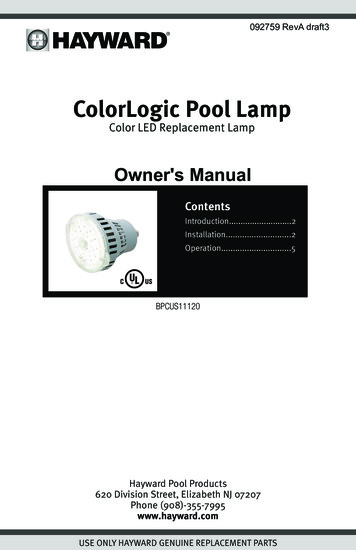
Product SpecificationsDimensionsGeneral InformationIntroductionThis manual contains information for the proper installation and operation of the Hayward PowerFlo Matrix pump.WARNING - Read and follow all instructions in this owner’s manual and on the equipment. Failure tofollow instructions can cause severe injury and/or death.Product Features The above-ground industry’s largest above-ground strainer basket for large debris collection with minimalmaintenance.Horizontal/Vertical Discharge Feature – Simply converts from horizontal to vertical discharge orientationwith the press of a button.Quick connect intake and discharge pipe connection.‘C’ clip connector allows for easy disengagement of strainer housing in a matter of seconds for hassle-freemaintenance.Heavy duty, high performance motor with integrated automatic thermal overload protector for years ofoperation.High quality impeller with wide openings to prevent clogging by leaves and large debris.Durable, corrosion-proof housing for years of dependable service and all-weather performance.Heat resistant, double-sized mechanical pump seal for long, lasting efficiency.Energy-efficient, protected rear-mounted switch.Integral drain plug for easy winterization of pumpInstallation InstructionsPump LocationLocate the system below the pool water line, for best pumpperformance.Install pump on a firm, level base or pad to meet all local andnational codes. The field supplied base or pad must be level.Though the pump is designed for outdoor use, it is stronglyadvised to protect the electrical components from theweather. Select a well-drained area, one that will not floodwhen it rains. Pump motors require free circulation of air forcooling. Do not install pump in a damp or non-ventilatedlocation.USE ONLY HAYWARD GENUINE REPLACEMENT PARTS4
Pump MountingFasten pump to base or pad with screws or bolts to reduce vibration and stress on pipe or hose joints.Hayward recommends a minimum clearance around the pad of 18” to allow adequate access for servicing pump andpiping.PlumbingInstalling union connections at the suction and outlet ports is recommended, to facilitate servicing of pump and toallow for indoor storage during the winter months,.Use Teflon tape to seal threaded connections on molded plastic components. All plastic fittings must be new orthoroughly cleaned before use. NOTE: Do NOT use Plumber’s Pipe Dope as it may cause cracking of the plasticcomponents.When applying Teflon tape to plastic threads, wrap the entire threaded portion of the male fitting with one to twolayers of tape. Wind the tape clockwise as you face the open end of the fitting, beginning at the end of the fitting.The pump suction and outlet ports have molded-in thread stops. Do NOT attempt to force hose connector fittingpast this stop. It is only necessary to tighten fittings enough to prevent leakage. Tighten fitting by hand and thenuse a tool to engage fitting an additional 1 ½ turns. Use care when using Teflon tape as friction is reducedconsiderably; do NOT over-tighten fitting or you may cause damage. If leaks occur, remove connector, clean off oldTeflon tape, re-wrap with one to two additional layers of Teflon tape, and re-install connector.ElectricalWARNING – Risk of Electric Shock. All electrical wiring MUST be in conformance with applicable localcodes, regulations, and the National Electric Code (NEC). All electrical wiring should be performed by a qualifiedprofessional. Hazardous voltage can shock, burn, and cause death or serious property damage. To reduce the risk ofelectric shock, do NOT use an extension cord to connect unit to electric supply. Provide a properly located electricalreceptacle. Before working on any electrical equipment, turn off power supply to the equipment. To reduce the risk ofelectric shock replace damaged wiring immediately. Locate conduit to prevent abuse from lawn mowers, hedge trimmersand other equipment. Do NOT ground to a gas supply line.WARNING – Risk of Electric Shock Failure to ground all electrical equipment can cause serious or fatalelectrical shock hazard. Electrical ground all electrical equipment before connecting to electrical power supply.WARNING – Risk of Electric Shock . The electrical equipment must be connected only to a supply circuit thatis protected by a ground-fault circuit-interrupter (GFCI). Such a GFCI should be provided by the installer and should betested on a routine basis. To test the GFCI, push the test button. The GFCI should interrupt power. Push reset button.Power should be restored. If the GFCI fails to operate in this manner, the GFCI is defective. If the GFCI interrupts powerto the electrical equipment without the test button being pushed, a ground current is flowing, indicating the possibilityof an electrical shock. Do not use this electrical equipment. Disconnect the electrical equipment and have the problemcorrected by a qualified service representative before using.Insure that the electrical supply available agrees with the motor’s voltage, phase, and cycle, and that the wire size isadequate for the H.P. (KW) rating and distance from the power source.VoltageVoltage at motor MUST NOT be more than 10% above or below motor name plate rated voltage, or motormay overheat, causing overload tripping and reduced component life. If voltage is less than 90% or morethan 110% of rated voltage when motor is running at full load, consult power company.Grounding/BondingWARNING – Risk of Electric ShockFailure to bond all electrical equipment to pool structure will increase risk for electrocutionand could result in injury or death. To reduce the risk of electric shock, see installation instructions and consult a professionalelectrician on how to bond all electrical equipment. Also, contact a licensed electrician for information on local electrical codesfor bonding requirements.Notes to electrician: Use a solid copper conductor, size 8 or larger. Run a continuous wire from external bonding lug toreinforcing rod or mesh. Connect a No. 8 AWG (8.4 mm2) [No. 6 AWG (13.3 mm2) for Canada] solid copper bonding wire to thepressure wire connector provided on the electrical equipment and to all metal parts of swimming pool, spa, or hot tub, and metalpiping (except gas piping), and conduit within 5 ft. (1.5 m) of inside walls of swimming pool, spa, or hot tub.IMPORTANT - Reference NEC codes for all wiring standards including, but not limited to, grounding, bonding and other generalwiring procedures.Permanently ground motor. Use green ground terminal provided under motor canopy or access place; use size andtype wire required by code. Connect motor ground terminal to electrical service ground.USE ONLY HAYWARD GENUINE REPLACEMENT PARTS5
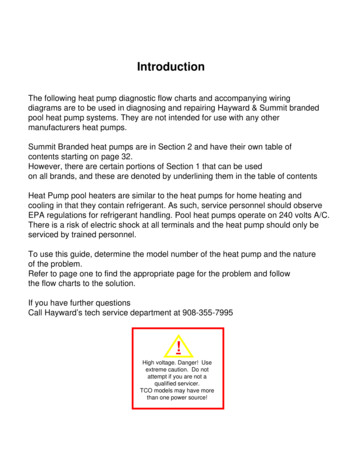
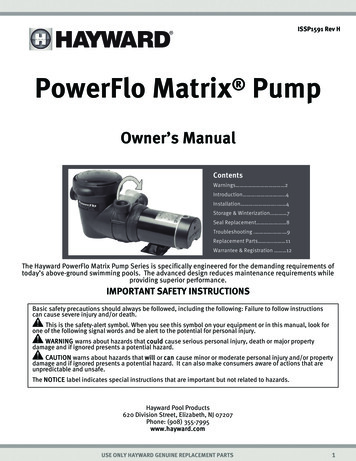
WiringIf other lights or appliances are also on the same circuit, be sure to add their amp loads before figuring wireand circuit breaker sizes. (NOTE: If unsure how to do this or if this is confusing, consult a licensedelectrician). Use the load circuit breaker as the Master On-Off switch.NOTE: If you do not use conduit when wiring motor, be sure to seal wire opening on end of motor to preventdirt, bugs, etc., from entering.New Installation – Start-Up & OperationSelecting Pump’s Discharge Position (4 Steps)Your Hayward Power-Flo Matrix pump can be easily positioned for horizontal or vertical water discharge.Step 1: Remove ALL plumbing attached to pump. Remove pumpfrom base (if applicable).Step 2: Remove strainer housing. Disengage and lift off strainer cover. Remove strainer basket. Lift up on strainer ‘C’ clip and remove. (See Fig. 1) Slide strainer housing forward and remove.Step 3: Press positioning button located on pump housing androtate discharge port to desired position.(NOTE: Discharge port will only rotate ¼ turn.)Step 4: Assemble the pump by following the above directions in the reverse manner.Figure 1Prior to Start-UpFill strainer housing with water to suction pipe level. NEVER operate the pump without water. Water acts as acoolant and lubricant for the mechanical shaft seal.WARNING – NEVER run pump dry. Running pump dry may damage seals, causing leakage andflooding. Fill strainer housing with water before starting motor.CAUTION – Do NOT add chemicals to pool/spa system directly in front of pump suction. Addingundiluted chemicals may damage pump and voids warranty.CAUTION – Before removing strainer cover:1. STOP PUMP before proceeding.2. CLOSE VALVES in suction and outlet pipes.3. RELEASE ALL PRESSURE from pump and piping system.WARNING – If pump is being pressure tested, be sure pressure has been released before removingstrainer cover.Priming Pump Clean and lubricate strainer cover O-ring with "Jack's 327" each time it is removed.Clean and inspect O-ring; re-install on strainer cover.Replace strainer cover on strainer housing; turn clockwise to tighten cover.NOTE: Tighten strainer cover by hand only (no wrenches) ¼ turn.Open all valves before starting system.Release all air from filter and piping system. See filter owner’s manual.With suction and outlet valves open and water source higher than the pump and flowing, pump will primeitself.If pump does NOT prime within ten minutes, stop motor and determine cause. Be sure all suction and dischargevalves are open when pump is running. See Troubleshooting Guide.USE ONLY HAYWARD GENUINE REPLACEMENT PARTS6
Storage/WinterizationWARNING – Explosion Hazard. Purging the system with compressed air can cause components toexplode, with risk of severe injury or death to anyone nearby. Use only a low pressure (below 5 PSI),high volume blower when air purging the pump, filter, or piping.CAUTION – Allowing the pump to freeze will void the warranty.CAUTION – Do NOT use anti-freeze solutions (except propylene glycol) in your pool/spa system.Propylene glycol is non-toxic and will not damage plastic system components; other anti-freezes arehighly toxic and may damage plastic components in the system.Gravity drain system as far as possible.Storing Pump for WinterizationWARNING – ELECTRICAL HAZARD, To avoid dangerous or fatal electrical shock hazard, turn OFF power tomotor before draining pump.Drain all water from pump and piping when expecting freezing temperatures or when storing pump.1. Drain water level below all inlets to the pool.2. Remove drain plug from bottom of strainer body.3. Disconnect pump from base.4. Once the pump is drained of water, re-install the strainer lid and strainer plug.5. Store pump in a dry enclosure. Keep motor dry and covered during storage. To avoidcondensation/corrosion problems, do NOT cover or wrap pump with plastic film or bags.Start-Up for Winterized Equipment1.2.3.4.Securely mount pump to base.Install all intake and output fittings and piping.Refill pool to proper water level.Prime pump according to instructions.USE ONLY HAYWARD GENUINE REPLACEMENT PARTS7
Shaft Seal Change InstructionsCAUTION -Only qualified personnel should attempt rotary seal replacement. Contact your local authorizedHayward Dealer or service center if you have any questions.WARNING - Read and follow all instructions . Failure to follow instructions can cause severe injuryand/or death.WARNING – Risk of Electric Shock Failure to turn off power can cause serious or fatal electrical shock hazard.Disconnect all electrical power service to pump before beginning shaft seal replacement.Exercise extreme care in handling both the rotating and the stationary sections of the two-part replacement seal. Foreignmatter or improper handling will easily scratch the graphite and ceramic sealing ut off water flow to pump by closing appropriate valves or by plugging both the skimmer outlet port and returnport to pool. Disconnect piping or hoses from the motor/pump assembly.Remove the strainer by disengaging and removing the strainer cover. Remove the basket. Lift up on strainer ‘C’ clipand remove. Finally, slide strainer housing forward and remove.Unscrew eight (8) screws and remove pump cover, exposing the impeller.Remove the canopy or the shaft cover plate from the end of motor opposite the impeller.Hold the motor shaft securely by either inserting a screwdriver in slot at end of shaft or by using an open-end wrenchto engage the flat surfaces provided near end of motor shaft. Rotate the impeller in a counterclockwise direction andremove it from the motor shaft.Note how the steel spring section of the old seal is positioned on impeller hub and remove it by pulling from theimpeller.Loosen four (4) motor through bolts from the back of motor and remove pump housing/shroud from the front of themotor.Remove the ceramic stationary portion of the old seal by pressing the white ceramic seat out of the pump housingrecess. If assembly is tight, tap lightly from the “motor” side.Clean and lubricate the impeller stem and the pump housing recess with a dilute solution of non-granulated liquidtype soap. Do not use petroleum or silicone lubricants as these can contribute to seal leakage.Press the new rotating portion of the seal assembly onto the impeller stem with the polished black graphite surfacefacing away from the impeller.Carefully press the stationary ceramic portion of the seal into the recess of the pump housing/shroud, with thepolished flat surface facing out.Carefully insert the motor shaft through the pump housing/shroud and align with white ceramic stationary sealassembly in place and secure the motor to pump housing/shroud with four (4) motor through bolts removed in step#7. Be sure motor base and pump discharge port are positioned properly. Alternately tighten the motor throughbolts until the pump housing is secure. Make certain motor shaft turns freely before proceeding.Screw the impeller (clockwise) with the rotating portion of seal in place onto the motor shaft. Hand-tighten theimpeller in place.Clean (replace if necessary) the O-ring and replace on pump cover. Assemble the pump cover to the pump housing/shroud with the eight (8) screws removed in step #3. Tighten screws alternately and evenly.Re-assemble strainer by sliding strainer housing onto pump cover. Install strainer ‘C’ clip by pushing clip down ontogrooved pump cover coupling. Insert basket and fasten strainer cover.Reconnect pump to the piping or hoses provided. Open all valves and make sure that the pump strainer housing isfull of water before restarting the pump.USE ONLY HAYWARD GENUINE REPLACEMENT PARTS8
TroubleshootingMotor Will NOT Start – Check For:1. Improper or loose wiring connections; open switches or relays; tripped circuit breakers, GFCI’s, or blown fuses.2. Manually check rotation of motor shaft for free movement and lack of obstruction. (See steps 4 & 5 of “ShaftSeal Change Instructions” in this manual.)3. If you have a timer, be certain it is working properly. Bypass it if necessary.Motor Shuts OFF – Check For:1. Undersized wiring; loose connections; etc.2. Low voltage at motor or power drop (frequently caused by undersized wiring or extension cord use).3. Mechanical binding and electrical overload.NOTE: Your Hayward pump motor is equipped with an “automatic thermal overload protector.” The motor willautomatically shut off if power supply drops before heat damage can build up causing windings to burn out. The“thermal overload protector” will allow the motor to automatically restart once the motor has cooled, provided thepower source is again up to proper levels. It will continue to cut On/Off until the problem is corrected. Be sure tocorrect cause of overheating.Motor Hums, But Does NOT Start – Check For:1. Centrifugal switch stuck in OPEN position.2. Binding of motor shaft.Pump Won’t Prime1.Make sure pump/strainer housing is filled with water and the cover O-ring is clean, also be sure it is properlyseated in the cover O-ring groove. Make sure strainer cover is locked firmly in position and lubricated with“Jack’s 327.”2. Make sure all suction and discharge valves are fully open and not blocked, that pool water level is at properlevel, and that skimmer weir is not hung up or stuck on skimmer wall.3. Block off to determine if pump will develop a vacuum. You should have 5”-6” of vacuum at the strainer cover(Only your pool dealer can confirm this with a vacuum gauge). You may be able to check by removing theskimmer basket and holding your hand over the bottom port with skimmer full and pump running. If no suctionis felt, check for line blockage.a. If pump develops a vacuum, check for blocked suction line or dirty strainer basket, an air leak in thesuction piping may be the cause.b. If pump does not develop a vacuum and pump has sufficient “priming water”:i. Re-check strainer housing cover and all threaded connections for suction leaks. Check if allhose clamps are tight.ii. Check voltage to ensure that the motor is rotating at full RPM’s.iii. Open housing cover and check for clogging or obstruction in suction. Check impeller for debris.iv. Remove and replace shaft seal only if it is leaking.Low Flow – Generally, Check For:1. Clogged or restricted strainer or suction line; undersized pool piping.2. Plugged or restricted discharge line of filter, valve partially closed (high gauge reading).How to correct: Sand filters – backwash as per manufacturer’s instructions; D.E. filters – backwash as permanufacturer’s instructions; Cartridge filters – clean or replace cartridge.3. Air leak in suction (bubbl
Hayward Pool Products 620 Division Street, Elizabeth, NJ 07207 Phone: (908) 355-7995 www.hayward.com ISSP1591 Rev H. WAR fo WAR Suction in s severe inju Hair Entra Limb Entra cracked, m Body Suct Eviscerati sump or su disembowe Mechanic opening of WARN o W be ap o D o D o Th o N o Re o In gu o In WAR suction WAR materia WAR replace CAUT being u