Transcription
ETA-Danmark A/SGöteborg Plads 1DK-2150 NordhavnTel. 45 72 24 59 00Fax 45 72 24 59 04Internet www.etadanmark.dkAuthorised and notified accordingto Article 29 of the Regulation (EU)No 305/2011 of the EuropeanParliament and of the Council of 9March 2011MEMBER OF EOTAEuropean Technical Assessment ETA-16/0864 of 2022/05/17General PartTechnical Assessment Body issuing the ETA and designated according to Article29 of the Regulation (EU) No 305/2011: ETA-Danmark A/STrade name of theconstruction product:TCC-II Ø7,3x150 and TCC-II Ø9,0x180 mm ConnectorsProduct family to which theabove construction productbelongs:Self-tapping screws for use in wood-concrete slab kitsManufacturer:Manufacturing plant:E.u.r.o. Tec GmbHUnter dem Hofe 5D-58099 HagenTel. 49 2331 / 6245 - 0Fax 49 2331 / 6245 - 200Internet www.eurotec.teamHeld on file by ETA-Danmark A/SThis European TechnicalAssessment contains:11 pages including 3 annexes which form an integralpart of the documentThis European TechnicalAssessment is issued inaccordance with Regulation(EU) No 305/2011, on thebasis of:European Assessment Document (EAD) no EAD130090-00-0303 “Wood-concrete composite slab withdowel-type fasteners”This version replaces:The ETA with the same number issued on 2016-11-29
Page 2 of 11 of European Technical Assessment no. ETA-16/0864, issued on 2022-05-17Translations of this European Technical Assessment inother languages shall fully correspond to the originalissued document and should be identified as such.Communication of this European Technical Assessment,including transmission by electronic means, shall be infull (excepted the confidential Annex(es) referred toabove). However, partial reproduction may be made, withthe written consent of the issuing Technical AssessmentBody. Any partial reproduction has to be identified assuch
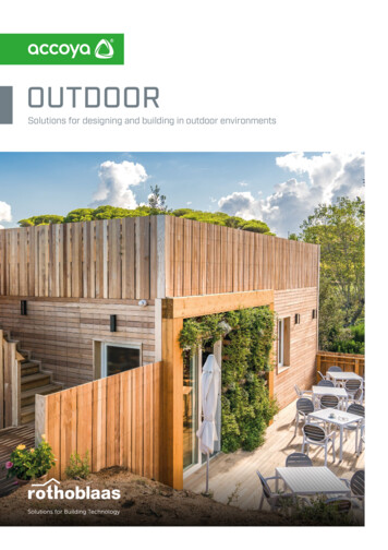
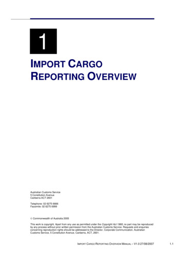
Page 3 of 11 of European Technical Assessment no. ETA-16/0864, issued on 2022-05-17IISPECIFIC PART OF THEEUROPEAN TECHNICALASSESSMENT1Technical description of productThis ETA is an assessment of the TCC-II Ø7,3x150 andTCC-II Ø9,0x180 mm Connectors for wood-concretecomposite slab kits. The diameter of the TCC-IIØ7,3x150 connectors is 7,3 mm, the length is 150 mm.The diameter of the TCC-II Ø9,0x180 connectors is 9,0mm, the length is 180 mm. Shape and tolerances of thescrews are given in Annex 3.The kits are individually designed to meet therequirements put on the works.E.u.r.o. Tec GmbH delivers the TCC-II Ø7,3x150 andTCC-II Ø9,0x180 mm Connectors for the compositeaction to be used as kit components. The compositemembers may be prefabricated at factory, or they may becomposed at the building site. The proper function of thewood-concrete composite slabs provides for thefollowing components to be added in the factory or at thebuilding site: Concrete slab, according to EN 206-1, andreinforcement according to EN 10080 and nationalregulations either prefabricated or cast at the buildingsite.In the case of concrete cast at the building site:formwork, e.g. timber boards or wood based panel.This is an optional intermediate layer between theconcrete and the timber. When the concrete slabs areprefabricated, no intermediate layer between timberand concrete is needed.In the case of concrete cast at the building site: lateralmoulding along the edges of the slab.Timber members, e.g. glulam according to EN14080, sawn softwood timber according to EN14081-1, LVL according to EN 14374 or crosslaminated timber according to ETA.The concrete flange is loaded in compression. The timbermembers are usually parallel or almost parallel.This ETA covers screws for composite members withminimum concrete flange depths of 50 mm and minimumtimber member depths of 100 mm. The maximumconcrete flange depth is 70 % of the timber memberdepth. Typical span widths for the construction are up to8 m with sawn softwood timber members, 10 m with LVLmembers and 14 m with glulam members but larger spanwidths also are possible.A typical composite member is shown in figure 1.1a ofAnnex 1. Screws are shown in figure 1.1b.2Specification of the intended use ument(hereinafter EAD)TCC-II Ø7,3x150 and TCC-II Ø9,0x180 mm Connectorsare intended to be used in structural composite memberssuch as floor, roof, or wall constructions in service classes1 and 2 as defined in EN 1995-1-1 subject to static orquasi static loading. In addition, use class 3.1 as definedin EN 335-1 (exterior, above ground, protected) ispossible, as balconies.The verification and assessment methods on which thisEuropean Technical Assessment is based lead to theassumption of a working life for the screw of at least 50years for the TCC-II Ø7,3x150 and TCC-II Ø9,0x180mm Connectors.The indications given on the working life cannot beinterpreted as a guarantee given by the manufacturer, butare to be regarded only as a means for choosing the rightproduct in relation to the expected economicallyreasonable working life of the works.
Page 4 of 11 of European Technical Assessment no. ETA-16/0864, issued on 2022-05-173Performance of the product and references to the methods used for its assessmentCharacteristicAssessment of characteristic3.1 Mechanical resistance and stability (BWR 1)*)Structural performanceWood-concrete composite slabs including TCC-IIØ7,3x150 and TCC-II Ø9,0x180 mm Connectors areused and manufactured according to an individualdesign made by a structural engineer responsible for thedesign of works on a case by case basis. Wood-concretecomposite floors may function as directly load bearingand structural bracing members. The structuralperformance of them shall be considered in accordancewith the limit state design principles specified inEurocodes.The performance of the composite slab is outside of thisETA.The screws are made of case hardened steel as specifiedin the control plan and corrosion protected with a zinccoating.Geometry of the screws is defined in Annex 3.Mechanical properties of TCC-II Ø7,3x150 and TCCII Ø9,0x180 mm Connectors and applicable creep andduration of load factors for composite members aregiven in Annex 2.3.2 Safety in case of fire (BWR 2)Reaction to fireTCC-II Ø7,3x150 and TCC-II Ø9,0x180 mmConnectors including the zinc coating are classifiednon-combustible in accordance with EC Decision2000/147/EC and fulfil the requirements of class A1according to EN 13501-1.3.3 Hygiene, health and the environment (BWR 3)Influence on air qualityThe product does not contain/release dangeroussubstances specified in TR 034, dated March 2012.*) See additional information in section 3.4 – 3.5.In addition to the specific clauses relating to dangerous substances contained in this European technical Assessment,there may be other requirements applicable to the products falling within its scope (e.g. transposed European legislationand national laws, regulations and administrative provisions). In order to meet the provisions of the ConstructionProducts Regulation, these requirements need also to be complied with, when and where they apply.
Page 5 of 11 of European Technical Assessment no. ETA-16/0864, issued on 2022-05-173.4General aspectsE.u.r.o. Tec GmbH delivers TCC-II Ø7,3x150 andTCC-II Ø9,0x180 mm Connectors intended to becomponent in wood-concrete composite slabs inaccordance with the provisions of this EuropeanTechnical Assessment. TCC-II Ø7,3x150 and TCC-IIØ9,0x180 mm Connectors are manufactured in thefactory in accordance with the provisions of thisEuropean Technical Assessment.TCC-II Ø7,3x150 and TCC-II Ø9,0x180 mmConnectors shall be installed on the basis of a specificstructural design for each composite slab installation.Load bearing capacities to be used in the design aregiven in Annex 2.The design also shall take into account any aspectsregarding installation of the kit components, as anytemporary bracing and supporting. Wood-concretecomposite slabs shall be installed by appropriatelyqualified personnel, following the installation plan.Only TCC-II Ø7,3x150 and TCC-II Ø9,0x180 mmConnectors without any defects are allowed to be used.Before concrete is poured, the person responsible for thedesign of the works shall check the set of the TCC-IIØ7,3x150 and TCC-II Ø9,0x180 mm Connectors to bein accordance with the design. The manufacturer shallensure that the information of these provisions is givento those concerned.3.5 Aspects related to the performance of theproduct3.5.1 Corrosion protection in service class 1 and 2.Durability of the finished composite slab is not coveredby this ETA.Durability of the TCC-II Ø7,3x150 and TCC-IIØ9,0x180 mm Connectors is provided for by theprotective zinc coating for a mean thickness of 5 µm
Page 6 of 11 of European Technical Assessment no. ETA-16/0864, issued on 2022-05-174 Assessment and verification of constancyof performance (AVCP)4.1 AVCP systemAccording to the decision 2000/447/EC of the EuropeanCommission, the system(s) of assessment andverification of constancy of performance (see Annex Vto Regulation (EU) No 305/2011) is 1.5Technical details necessary for theimplementation of the AVCP system, asforeseen in the applicable EADTechnical details necessary for the implementation ofthe AVCP system are laid down in the control plandeposited at ETA-Danmark prior to CE marking.Issued in Copenhagen on 2022-05-17 byThomas BruunManaging Director, ETA-Danmark
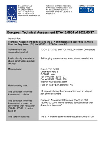
Page 7 of 11 of European Technical Assessment no. ETA-16/0864, issued on 2022-05-17ANNEX 1WOOD-CONCRETE COMPOSITE SLAB COMPOSED WITHTCC-II Ø7,3X150 AND TCC-II Ø9,0X180 MM CONNECTORSFigure 1.1a Elevation on (left) and cross-section through (right) a composite member with TCC-II Ø7,3x150and TCC-II 9x180 mm screwsTable 1.1 – Minimum spacing, end and edge distances for TCC-II Ø7,3x150 and TCC-II Ø9,0x180 mm screwsin mmTCC-II Ø7,3x150TCC-II Ø9,0x180 mmSpacing parallel to grain a180100Spacing perpendicular to grain a23045End distance a3,c80100Edge distance a4,c3036The composition of the screw materials is deposited at ETA Danmark.The length and diameter of the screws is given in Annex 3. More exact description of the shape and tolerancesof the screws are referred to under 3.2.2.1 in the Control plan.
Page 8 of 11 of European Technical Assessment no. ETA-16/0864, issued on 2022-05-17ANNEX 2MECHANICAL PROPERTIESResistance and stiffnessStructural modelComposite members with TCC-II Ø7,3x150 and TCC-II Ø9,0x180 mm Connectors are to be designed taking intoaccount the influence of the slip occurring in the joints. A method for the calculation of the load bearing capacityand the deformation of mechanically jointed beams or columns is given in Annexes B and C of Eurocode 5 Part1-1: General – Common rules and rules for buildings. Calculations should be carried out assuming a linearrelationship between force and slip. Alternative methods for the calculation based on numerical models are alsoapplicable.For the determination of the internal forces and moments an elastic behaviour of the concrete may be assumed ifthe tensile stress in the concrete does not exceed twice the concrete tensile strength.Friction between timber and concrete may be taken into account, if the friction coefficient may be assumed as μ 0,25.In order to apply the friction between the concrete slab and the timber beam for the calculation of the system, thefollowing conditions shall be fulfilled:- Static system as single span or continuous girder- Predominantly static load- Screws arranged unidirectional with systematically existing compression force between wood andconcrete for reasons of equilibriumApart from the design of the composite member, the load-carrying-capacity of the concrete layer spanningbetween the timber beams and the shear capacity of the timber member in the perimeter area around the screwsshould be checked.The timber beam may only be arranged on top of the concrete slab, if tensile forces perpendicular to the joint linebetween timber and concrete are transferred by screws arranged perpendicular to the joint line.The support of the wood concrete composite elements shall be carried out via the lower cross-sectional part eitherdirectly by contact or by appropriate connections.
Page 9 of 11 of European Technical Assessment no. ETA-16/0864, issued on 2022-05-17Design of the wood-concrete composite slabThe design of the wood-concrete composite slab in the ultimate and the serviceability limit states shall take intoaccount the influence of creep, concrete shrinkage and moisture changes. The verification of the limit states is tobe performed both for the initial state (t 0) and the final state (t ). The influence of creep and moisturechanges may be taken into account by reducing the modulus of elasticity of the timber and concrete and the slipmodulus to be used in calculations analogous with EN 1995-1-1. The values of the deformation factors kdef givenin Table 2.1 should be used. For prefabricated concrete slabs, the concrete shrinkage may be disregarded.Table 2.1 – Values of kdef for timber, concrete and TCC-II Ø7,3x150 and TCC-II Ø9,0x180 mm ConnectorsMaterialService class12Solid timber, EN 14081-10,62,0Glued Laminated timber, EN 140800,62,0LVL, EN 143740,62,0Cross laminated timber, ETA0,82,0Concrete, EN 206-12,52,5TCC-II Ø7,3x150 and TCC-II Ø9,0x180 mm Connectors0,64,0connectionFor timber-concrete composite joints made with TCC-II Ø7,3x150 and TCC-II Ø9,0x180 mm Connectors the slipmodulus Kser per fastener under service load parallel to the shear plane should be taken from Table 2.2 with efin mm.Table 2.2 – Values of Kser for timber-concrete-joints with TCC-II Ø7,3x150 and TCC-II Ø9,0x180 mm ConnectorsKser in N/mmConnectorWith interlayerDirect contact between timber and concreteorientationd 9,0 mmd 7,3 mmd 9,0 mmd 7,3 mm90 6007001800220045 110 ef110 ef110 ef110 ef
Page 10 of 11 of European Technical Assessment no. ETA-16/0864, issued on 2022-05-17For timber-concrete composite joints made with TCC-II Ø7,3x150 and TCC-II Ø9,0x180 mm Connectors thecharacteristic load bearing capacity per fastener FRk parallel to the shear plane should be taken from Table 2.3with ρk in kg/m³ and d and ef in mm. Characteristic yield moment Myk is given in Table 2.4.Table 2.3 – Values of FRk for timber-concrete-joints with TCC-II Ø7,3x150 and TCC-II Ø9,0x180 mmConnectors.ConnectororientationWith interlayerFRk in NDirect contact between timber and concrete 4 My,kfh,1,kfh,2,k d t 1 1 fh,2,k d t 2 2 fh,2,k 90 4 My,k fh,2,k d 45 where:FRkis the characteristic load-carrying capacity per conenctor in N;tfh,1,kfh,2,kis the interlayer thickness in mm;is the characteristic embedment strength in the interlayer in MPa;is the characteristic embedment strength in the timber member in MPa;dMy,kis the conenctor diameter in mm;is the characteristic fastener yield moment in Nmm;is the characteristic withdrawal capacity in N;Fax, ,Rk ef k 𝜌𝑘 0,8𝐹𝑎𝑥,𝛼,𝑅𝑘 𝑓𝑎𝑥,𝑘 𝑑 𝑒𝑓 ()350is the penetration depth of the connector in the timber member in mm;is the characteristic timber member density in kg/m³;Friction coefficient; 0,25Table 2.4 – Properties of TCC-II Ø7,3x150 and TCC-II Ø9,0x180 mm ConnectorsTCC-II conenctor with diameterYield moment My,k [Nm]Tensile capacity ftens,k [kN]Withdrawal parameter fax,k [N/mm²]d 7,3 mm25d 9,0 mm342312,63011,5Resistance to fireSimplified rules in EN 1995-1-2 for calculation of resistance to fire in case of screws are applicable forconstructions made by TCC-II Ø7,3x150 and TCC-II Ø9,0x180 mm Connectors.Thus, in design of works, fire resistance of the timber members may be determined according to EN 1995-1-2 andthe fire resistance of the concrete flange according to EN 1992-1-2, if the national rules allow for calculation.
Page 11 of 11 of European Technical Assessment no. ETA-16/0864, issued on 2022-05-17ANNEX 3Drawing of the TCC-II Ø7,3x150 and TCC-II Ø9,0x180 mm ConnectorsTolerances held on file by ETA-Danmark A/S
TCC-II Ø7,3x150 and TCC-II Ø9,0x180 mm Connectors Product family to which the above construction product . Tel. 49 2331 / 6245 - 0 Fax 49 2331 / 6245 - 200 Internet www.eurotec.team Manufacturing plant: Held on file by ETA-Danmark A/S This European Technical Assessment contains: 11 pages including 3 annexes which form an integral part of .