Transcription
International Journal of Scientific & Engineering Research Volume 9, Issue 3, March-2018ISSN 2229-55181341Static and Dynamic Analyses of a Ship PropellerArjun B Curam, Ejaaz Ahmed, M Vishaal Rao, AkashAbstract— Ships and underwater vehicles like submarine and torpedoes use propellers for propulsion. These propellers consist of a varying number ofblades, and have also been constructed using different materials as time has passed by. The purpose of this project was to model ship propellers basedon a standard 4 blade INSEAN E779a model, and varying it with respect to materials, number of blades and rake angles. Here, the procedure used tomodel and analyse the propeller blades have also been discussed. SOLIDWORKS v2013 was the software used to model the propellers, while ANSYS14.5 was used to perform Static Structural and Computational Fluid Dynamic Analyses of these propellers. The Analyses were carried out for 2materials, namely Aluminium and Carbon- Fibre Reinforced Plastic, for rake angles of 0 ̊ and 4.05̊. The results obtained from the CFD and StaticStructural analyses helped determine which propeller performed the best when being compared across different parameters like velocity of water aroundthe propeller, pressure developed by the propeller, stresses, deformations and strains developed within the propeller when subjected to a thrust. Themodifications made to the propeller in terms of material, number of blades and rake angles suggested which variant of the propeller is best suited fordifferent requirements of the Ship. For higher speeds, the 3 bladed propellers proved to be more effective, while the 4 bladed propellers were seen toexperience lesser stress and deformations due to the thrust. Along with the effect of the rake angle, the features and disadvantages of CFRP too havebeen discussed.Index Terms— Aluminium 5052, ANSYS, , Carbon Fibre Reinforced Plastic, Computational Fluid Dynamics, Rake Angle, Static StructuralAnalysis, SOLIDWORKS.—————————— —————————— Mass density 2.68 gm/cc1. INTRODUCTION Damping coefficient 0.03A ship is a large watercraft that travels around deep waterbodies like the oceans, carrying passengers or goods forProperties of CFRPvarious purposes like defence, research and fishing. The Young’s Modulus 116.04 GPavarious types of ships include high-speed craft, tugboats, Poisson ratio 0.28factory ships, dry cargo ships, liquid cargo Ships, passenger Mass density 1.6 gm/ccvessels, liners, luxury cruising yachts, warships. Yet, no matter Damping coefficient 0.018how light or heavy they are, their movement is enabled by aphenomenon called propulsion. This is possible by a machine Evidently, the density, damping coefficient and Poisson’sRatio of CFRP is lesser than that of Aluminium and it’s viceknown as propeller.versa when it comes to Young’s Modulus.Marine propulsion is the mechanism of generating thrust tomove a ship across the water surface. Most modern ships are Disadvantages of CFRPpropelled by mechanical systems consisting of an engineturning a propeller. Marine engineering is the discipline Like any other material, CFRP too has its own disadvantagesconcerned with the engineering design of marine propulsion that would dissuade manufacturers from using it1. Carbon Fibre requires a mould in order to prepare ansystems.acceptable product, which is not very easy.In this project, a total 8 of ship propeller blades were modelled 2. Carbon Fibre is also a very expensive material.using the modelling software SOLIDWORKS. These propellers 3. Once a Carbon Fibre structure is dented, it cannot beconsisted of both 3 blades and 4 blades, and were designed by repaired like a structure made of any other conventionaltaking magnitude of skewness and rake Angles into account. metal. On damage to the structure, it will in all likelihood be[7] The .STEP files of these models were then transferred to the replaced.analysis software platform ANSYS, where they were analysed 4. Though a lot of research is being conducted, there has beenboth statically and dynamically. The blades were analysed for no clear cut solution to recycling products of Carbon Fibre2 materials, namely Aluminium 5052 and Carbon FibreReinforced Plastic (CFRP). A comparative study between these 2. PROPELLER TERMINOLOGYpropellers was made based on the stresses and strainsdeveloped in the propellers, deformations within the Rake: Rake is the amount in degrees that the blades of thepropellers, pressures created by the propellers, and variation propeller angle perpendicular to the hubof velocity of water around the propeller.Pitch: Pitch may be denoted as the unit distance moved by aProperties of Aluminium 5052point on the propeller when it completes one revolutionSkew: The transverse sweeping of a blade such that viewing Young’s Modulus 69.3 GPathe blades from the fore or aft shows an asymmetrical shape is Poisson ratio 0.33called Skew.IJSERIJSER 2018http://www.ijser.org
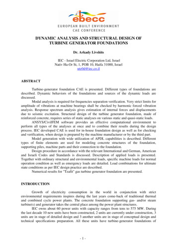
International Journal of Scientific & Engineering Research Volume 9, Issue 3, March-2018ISSN 2229-5518Radius: The distance from the centre of the hub to the bladetip.Hub: It is a solid cylinder located at the centre of the propeller,bored to accommodate the ShaftFig 2.1 Propeller Terminology3. LITERATURE SURVEY1342Palle Prasad, Lanka Bosu Babu [4] worked on the structuralanalysis of a CFRP (carbon fibre reinforced plastic) propellerblade which was a replacement to the Aluminium propellerblade. They subjected the propeller to external hydrostaticpressure on either side of the blade. From the output of theirstatic analysis and dynamic analyses of the marine propeller,they concluded that the propeller is assumed as a cantileverbeam and by varying the material for propeller blade fromCFRP to GFRP, the Von- Mises stress is reduced to apercentage of 31.4%.Vladimir Krasilnikov and at el[5] describe results ofnumerical prediction of unsteady forces acting on propellerblades using a Reynolds Averaged Navier Stokes (RANS)method. Here, different types of marine propellers weremeshed and applied to the analysis of open and poddedpropellers operating in oblique flow conditions. Theypresented results obtained using this method for poddedpropeller operating in pulling and pushing modes, and pointsout the differences in forces experienced. For these propellers,in the range of heading angles from -45 to 45 the RANSmethod showed predictions of unit and propeller forces whichagreed well with the test data.IJSERV. Ganesh and et al [1] modelled and analysed a propellerblade of a torpedo for its strength. CATIA software was usedfor developing the blade model, while modal analysis andstatic structural analysis were carried out for both Aluminiumand CFRP on ANSYS. By considering the design of thepropeller blade on the basis of a cantilever beam, the hub wastaken to be the fixed end where there was no deformation. Oncarrying out modal analysis for both aluminium andcomposite propellers, they found that the maximumdisplacement for composite propeller is less than theAluminium propeller.Mohammed Ahmed Khan and et al [2] carried out thedynamic analysis of Propellers of different materials, namelyAluminium, CFRP and GFRP. The solid model of propellerwas developed using CATIA V5 R17 and using HYPERMESH, a tetrahedral mesh was generated for said model. Theycarried out static, Eigen and frequency responses analyses ofboth aluminium and the composite propeller on ANSYS. Theyalso calculated inter- laminar shear stresses for compositepropeller by varying the number of layers and found that thepercentage variation was about 3.147%.Barru Harish and et al[3] focussed on the design procedure offour bladed marine propellers, placing specific interest onengines with 85 Bhp, and a ship moving at a speed of 30knots. The design was modelled on CATIA and Static analysiswas carried out on aluminium, R Glass, S2 glass and CFRP(Carbon Fibre Reinforced Plastics) materials on ANSYS.Material results were compared and the stresses obtainedwere well within the safe limits of elastic property of thematerials. .Dr. Y. Seetharama Rao and et al [6] presented a methodologyto design a propeller with a metal and composite material, andperform stress analysis in order to evaluate its effectivenessusing ANSYS software. Proposed methodology showedsubstantial improvements in metal propellers. Analyticalmethods were first carried out to find out stresses in a bladesection and then, the mean deflection; normal stress and shearstress were found for both metallic and composite propellerby using ANSYS. From their results of stress analysis, thestresses of composite propeller were obtained are within theallowable stress limit.Djahida Boucetta and Omar Imine [7] investigated theinfluence of parameters such as skew magnitude, thicknessand number of blades on the performances of propellers. Theystudied the open water performances of a conventional 3bladed propeller model DTMB 4148, and the flow around therotating propeller model was analysed in the steady stateusing RANS approach of the Fluent. They concluded that aparticular number of blades had a positive influence on theopen water characteristics, and the propeller with four bladesprovided the best efficiency. Lastly, they found that byincorporating a skew angle on the blade, it improved thehydrodynamic performances of the marine propeller.Abhijjet H. Kekan and P. S Kachare [8] explained howpropeller parameters were based on number of blades, sizing,power and rpm, speed of the ship. He modelled a propeller onCATIA, after which a mesh was generated usingIJSER 2018http://www.ijser.org
International Journal of Scientific & Engineering Research Volume 9, Issue 3, March-2018ISSN 2229-5518HYPERMESH. Static and harmonic analyses were bothperformed on ANSYS for Aluminium and Composite materialbased propellers. He found that the deflection of Compositepropeller was much lower than the Aluminium propeller,indicating its stiffness. Also, from the Harmonic Analysis, hefound out that the operating range of Composite propellerswere much higher than the Aluminium propellers.4. METHODOLOGY1.2.3.4.5.6.7.8.3 bladed and 4 bladed propellers, of StandardINSEAN E779a 4 bladed propeller are modelled onSolidworksThis standard propeller is Skewed by 20 , has a Rakeangle of 4.05 and a diameter of 227.2 mmPropellers are modified according to rake angleAnalytical calculations are done for thrust, pitch andthickness variation with radiusMeshing of these propeller models is carried out onANSYS v14.5Aluminium 5052 and CFRP materials are consideredfor both CFD and Static analysesStatic, CFD analyses of the propellers is carried out onANSYSComparative study is done based on Pressuredeveloped due to the propeller blades, Velocity ofwater around the propeller; Stresses, strains anddeformations developed within the propeller whensubjected to a thrust.1343[Assume Ratio 1/2; gear ratio(c) 1; slip(s) 0]rate(m) total blade area speed of theMass lowhrboat(5)Step 4: Calculate Advance Velocity, ThrustThe thrust (T) is equal to the mass flow rate (m) times thedifference in the velocity (v)T m (Vb – Va)(6)Where Advance Velocity Va Vb (1 w)(7)[w wake fraction]Step 5: Determine variation of Pitch and Thickness along the radiusTo determine the pitch along the radius of the propeller blade,the Pitch at 25%, 50%, 60%, 70%, 80%, 90% of radius beingrepresented by P0.25, P0.5, P0.6, P0.7, P0.8, P0.9, respectively wascalculated using the formulaPx (x) Radius of the propeller blades (Pitch/Diameter) Ratio(8)Similarly, the thickness of the blade section could be found forthe radii, using the blade thickness fraction 0.05 (t0/D),which meanst0 D 0.05(9)Hence, to estimate the thickness along the radius of thepropeller,t0 0.05 (R in percentage)(10)IJSERCalculationsA. Theoretical CalculationsSteps and EquationsGiven ratio of Pitch/ Diameter 1.1, hencePitch 227.2*1.1 249.92 mmTotal Area of the circle π* r2 π* 113.62 40567.113 mm2Total blade area 40567.113* 0.51 20689.23 mm2Step 1: Providing the geometric specifications of the PropellerDiameter of the Propeller 227.2 mmNumber of blades 4Propeller Model INSEAN E779AType of propeller Controllable pitch propellerMaterials considered Aluminium and CFRPSpeed [Step 2: Calculate Pitch, Total area of the circle, Total blade areaGiven ratio of Pitch/ Diameter 1.1Total Area of the circle π r 2Total blade area total area of the circle disc arearatioWhere Disc area ratio 0.51(1)(2)(3)Step 3: Calculate Boat Speed, Mass flow rateSpeed [RPMRatio]*[Pitchc]*[1 S100](4)RPMRatio]*[Pitchc]*[1 S1001000] [(0.5249.92)*(11 0)*(100)] 4998.4 x 60/10 29.99 km/hrBoat speed Vb 29.99/1.6093 mile/ hr 18.63 mile/hrMass flow rate/hr (m) total blade area* speed of the boat 20689.23* 10-6* 29.99* 103 620.47 m3/hrT m (Vb – Va)Va Vb* (1- w) 29.99* (1-0.25) 22.425 km/hrHence, Thrust (T) 620.47* (29.99-22.425)* 103 4693855.55 N 4.69 MNVariation of Pitch along the radiusP0.25 (25/ 100)* 113.6* 1.1 31.24 mmP0.5 (50/ 100)* 113.6* 1.1 62.48 mmP0.6 (60/ 100)* 113.6* 1.1 74.98 mmP0.7 (70 /100)* 113.6* 1.1 87.47 mmP0.8 (80/ 100)* 113.6* 1.1 99.97 mmP0.9 (90/ 100)* 113.6* 1.1 112.46 mmIJSER 2018http://www.ijser.org4
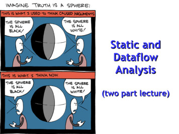
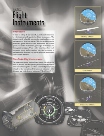
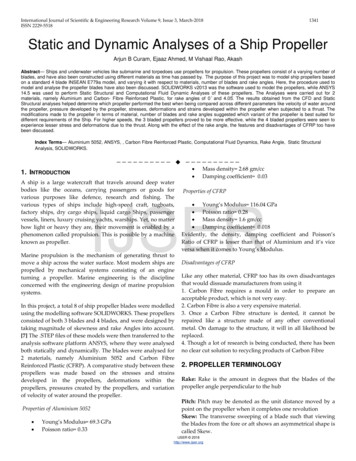
International Journal of Scientific & Engineering Research Volume 9, Issue 3, March-2018ISSN 2229-55181344Depending on the rake angle of 0 ̊ or 4.05 ̊, this rectangle iseither drawn at the centre of the hub length, or 7 mm belowrespectivelyP1.0 (100/ 100)* 113.6* 1.1 124.96 mmVariation of Thickness along the radiust0.1 0.1* 113.6* 0.05 0.568 mmt0.2 0.2* 113.6* 0.05 1.136 mmt0.3 0.3* 113.6* 0.05 1.704 mmt0.4 0.4* 113.6* 0.05 2.272 mmt0.5 0.5* 113.6* 0.05 2.84 mmt0.6 0.6* 113.6* 0.05 3.408 mmt0.7 0.7* 113.6* 0.05 3.976 mmt0.8 0.8* 113.6* 0.05 4.544 mmt0.9 0.9* 113.6* 0.05 5.112 mmt1.0 1.0* 113.6* 0.05 5.68 mm5. The rectangle at the central axis is lofted to the rectangleabove, and this forms the initial blade. Upon providingnecessary fillets at the blade edges, it is skewed by 20 ̊ whenviewed from the front. Also, a hole of 40 mm diameter is cut atthe rear end of the hub, which is where the shaft would beassembled6. The propeller blade is ready. Depending on the number ofblades, a circular pattern of 3 blades or 4 blades is provided,spaced equally around the circumference of the hubThe following images show the variation of Pitch andThickness against the % of Radius in graphical form, takingvalues from what were calculated above. The two graphs wereseen to increase linearly, which meant that the Pitch andThickness of the blade increased linearly from the Blade- Hubintersection up to the tip of the Blade.IJSERFig.4.3 4 bladed propeller Fig. 4.4 3 bladed propellerC. Cfd Analysis On Ansys WorkbenchFig 4.1 Pitch v/s % of Radius Fig. 4.2 Thickness v/s % of RadiusB. Solidworks ModellingThe following steps were followed in order to carry out theCFD analysis of the propeller blade on ANSYS Fluent. [3]Step 1: GeometryThe following were the steps involved in developing theSolidworks models of the propellers1. A horizontal line of 131.3 mm was drawn, and from thestarting point of the same line, a 30 mm vertical line wasdrawn. These lines represent the length and the radius of theHub of the Propeller respectively2. From the end of the radius line, a horizontal line of 74.9 mmwas drawn. From this point, a spline connected this line to theline representing the length of the propeller. This was curvedin such a way that it was concave to the centre of the surface3. This drawing was revolved about the length, thuscompleting the hub4. A rectangle of length 90 mm and breadth 15 mm was drawnat the centre of the propeller, perpendicular to its axis.Another rectangle of the same dimensions was drawn at aheight of 113.6 mm above the central axis, angled 74̊ to thehorizontal. This is the radius of the propeller blade.The .STEP files of the Solidworks models of the propellerswere chosen as the geometry for the Analysis. On choosing thegeometry, the DesignModeler is opened, which leads to Step 2Step 2: Creating DomainThe DesignModeler is opened and the propeller can beviewed. A sketch is chosen for a plane perpendicular to thelength of the hub (here, YZ Plane). The origin of this SketchingPlane is at the back end of the Propeller Hub. A horizontal lineis drawn 250 mm behind the axis, and from this very point, avertical line is drawn 200 mm up. A horizontal line of 586.4mm is drawn from the end of the vertical line. At this point, a400 mm vertical line is drawn downwards. The first 2 lines arenow cut, and two more horizontal lines of 586.4 mm and 400mm are drawn respectively, in order to form the rectangle.Now, the sketch was extruded symmetrically on both sides by200 mm and the operation was Add Frozen, thus generatingthe cuboidal domain. Booleans are subtracted with the TargetBody being the surrounding Domain, and the Tool Body beingIJSER 2018http://www.ijser.org
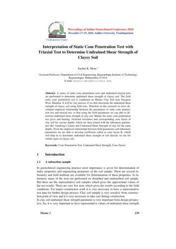
International Journal of Scientific & Engineering Research Volume 9, Issue 3, March-2018ISSN 2229-5518the Propeller inside it. This is crucial in order to obtain a goodmesh.Step 3: MeshingOn closing the DesignModeler, the Meshing model is opened.Here, Inlet, Outlet and Propeller Named Selections werecreated. The Tetrahedron meshing was applied, which was ofPatch Conforming Method. The Advanced Size Function usedwas Proximity and Curvature and the Relevance Centrechosen was Fine. A particular number of nodes and elementswere obtained.Step 4: SetupOn closing Meshing, the Fluent Setup is opened. Here, theInitial Solver settings were Steady Time, Pressure Based Typeand Absolute Velocity Formulation. The Models option wasmodified as Viscous- k epsilon, Realizable, Scalable WallFunctions. In Materials, Water was added as the fluid, whileAluminium 5052 was considered to be the solid material forthe propeller on 4 occasions, while CFRP was considered on 4other occasions. The Boundary Condition applied at the inletwas a velocity of 8.33 m/s of water. The Solution wasinitialised keeping in mind the inlet as reference values. TheCalculation was made to run for 50 iterations. A graph of xvelocity, y- velocity, k-epsilon and time/iter was obtained.Step 5: Results1345Here, the Model was again subject to the Tetrahedronmeshing, which was of Patch Conforming Method. TheAdvanced Size Function used was Proximity and Curvatureand the Relevance Centre chosen was Fine. A particularnumber of nodes and elements were obtained. The materialwas changed from the default setting to the required materialof the 2 available to us. CFRP proved to be lighter thanAluminium. The propeller was fixed at the hub, and at theintersections of the blades with the hub. [1] The calculatedvalue of Thrust, 4.69 MN was applied at the surface of thepropeller blades as a Force. [1] Finally, the solver settingsincluded Equivalent (Von- Mises) Stress, Elastic Strain andTotal Deformation.5. CFD ANALYSISThe following results were obtained upon completion of CFD.They include the Pressure contour, Velocity contour and theshape of the Streamline. The 4 bladed propellers had 627011nodes and 3487492 elements after being meshed. The 3 bladedpropellers had 486348 nodes and 2702161 elements after beingmeshedIJSERThe Results cell is opened, and here is where the streamline,Plane at YZ plane, velocity vector and even the pressurecontours were applied.D. Static Structural Analysis On Ansys WorkbenchThe following steps were followed in order to carry out theStatic Structural Analysis of the propeller bladeStep 1: Defining Material PropertiesBased on the Material chosen, the geometric data regardingdensity, Poisson’s Ratio, and Young’s Modulus were modifiedfor Aluminium 5052 and CFRP respectively. The values wereconsidered from the tables as mentioned in the previouschapter.Step 2: GeometryThe .STEP file was chosen again for each propeller, and thegeometry was obtained.Step 3: Meshing and Boundary ConditionsThe following settings were provided before performing theanalysisa. Initial Solver settingsSteady Time, Pressure Based Type and Absolute VelocityFormulation.b. ModelsViscous- k epsilon, Realizable, Scalable Wall Functions.c. MaterialsWater as the fluid, Aluminium 5052 or CFRP as the Solidwhenever requiredd. Boundary ConditionsInlet Velocity of water 8.33 m/sThe maximum pressure exerted by the propellers is seen to beat the intersection of the blade and the surface of the hub. Aswe look towards the tip of the propeller blade, the pressuredecreases, and the pressure is at its lowest in the regionsurrounding the blade.The velocity contour demonstrates how the velocity of waterchanges across the surface of the blade. It has a value of 8.33m/s at the inlet and decreases at the tip of the hub and alsobetween the contact of propeller blades and hub. As we looktowards the tip of the blades, the velocity of water is seen toincrease, while right behind the propeller hub, it has almost novelocity1.4 bladed Aluminium 5052 Propeller, Rake angle 4.05 ̊IJSER 2018http://www.ijser.org
International Journal of Scientific & Engineering Research Volume 9, Issue 3, March-2018ISSN 2229-5518Fig. 5.1 Pressure Contour2.Fig. 5.2 Velocity ContourFig. 5.7 Pressure Contour5.4 bladed Aluminium 5052 Propeller, Rake angle 0 ̊IJSERFig. 5.3 Pressure ContourFig. 5.4 Velocity Contour6.Fig 5.10 Velocity Contour3 bladed Aluminium 5052 Propeller, Rake angle 0 ̊4 bladed CFRP Propeller, Rake angle 4.05 ̊Fig 5.11 Pressure ContourFig. 5.5 Pressure Contour4.Fig.5.8 Velocity Contour3 bladed Aluminium 5052 Propeller, Rake angle 4.05 ̊Fig 5.9 Pressure Contour3.1346Fig. 5.6 Velocity Contour4 bladed CFRP Propeller, Rake angle 0 ̊7.4 bladed CFRP Propeller, Rake angle 4.05 ̊Fig. 5.13 Pressure Contour8.Fig 5.12 Velocity ContourFig. 5.14 Velocity Contour3 bladed CFRP Propeller, Rake angle 0 ̊IJSER 2018http://www.ijser.org
International Journal of Scientific & Engineering Research Volume 9, Issue 3, March-2018ISSN 2229-5518Fig 5.15 Pressure Contour1347Fig 6.3 Elastic StrainFig 5.16 Velocity ContourThe best performing propeller in terms of pressure createdand the velocity of water around it is observed to be the 3bladed CFRP propeller, with a rake angle of 4.05̊.2. 4 bladed Aluminium 5052 Propeller, Rake angle 0 ̊6. STATIC STRUCTURAL ANALYSISThe following results were obtained upon completion of StaticStructural Analysis. They include the Equivalent (Von- Mises)Stress, Elastic Strain and the total deformation. The followingwere the Boundary Conditions that were applied beforesolvingIJSERFig 6.4 Total DeformationFig 6.5 Von- Mises Stressa. Hub and points of contact between the blades and hubwere fixedb. Force of 4.69 MN was applied to the bladesThe maximum deformation is seen to be at the tip of thepropeller blade while the minimum is 0 mm, seen at the hubof the propeller.The value of the maximum Von- Mises Stress is at the point ofcontact between the propeller blade and the hub. From themiddle of the blade and even at the hub, a very small valueexistsThe maximum elastic strain is seen at the point of contactbetween the propeller blade and the hub. From the middle ofthe bade and even at the hub, a very small value exists.Fig 6.6 Elastic Strain3.4 bladed CFRP Propeller, Rake angle 4.05 ̊1. 4 bladed Aluminium 5052 Propeller, Rake angle 4.05 ̊Fig 6.7 Total DeformationFig 6.1 Total DeformationFig 6.2 Von- Mises StressIJSER 2018http://www.ijser.orgFig 6.8 Von- Mises Stress
International Journal of Scientific & Engineering Research Volume 9, Issue 3, March-2018ISSN 2229-5518Fig 6.15 Elastic StrainFig 6.9 Elastic Strain4. 4 bladed CFRP Propeller, Rake angle 0 ̊13486.3 bladed Aluminium 5052 Propeller, Rake angle 0 ̊IJSERFig 6.10 Total DeformationFig 6.11 Von- Mises StressFig 6.16 Total DeformationFig 6.18 Elastic StrainFig 6.12 Elastic Strain5. 3 bladed Aluminium 5052 Propeller, Rake angle 4.05 ̊Fig 6.13 Total DeformationFig 6.14 Von- Mises StressFig 6.17 Von- Mises Stress7.3 bladed CFRP Propeller, Rake angle 4.05 ̊Fig 6.19 Total DeformationIJSER 2018http://www.ijser.orgFig 6.20 Von- Mises Stress
International Journal of Scientific & Engineering Research Volume 9, Issue 3, March-2018ISSN 2229-5518Fig 6.21 Elastic Strain8.Fig 7.1 Stress vs Pressure3 bladed CFRP Propeller, Rake angle 0 ̊Fig 7.2 Stress vs Strain2. 4 bladed, Aluminium 5052 Propeller, Rake Angle 0 ̊IJSERFig.6.22 Total Deformation1349Fig 6.23 Von- Mises StressFig 7.3 Stress vs Pressure3.Fig 7.4 Stress vs Strain4 bladed, CFRP Propeller, Rake Angle 4.05 ̊Fig 6.24 Elastic StrainThe best performing propeller in terms of least deformation,least stress and strain developed is observed to be the 4 bladedCFRP propeller, with a rake angle of 4.05̊.Fig 7.5 Stress vs Pressure4.Fig 7.6 Stress vs Strain4 bladed, CFRP Propeller, Rake Angle 0 ̊7. RESULTS AND DISCUSSIONSThe graphs of Stress v Pressure have been drawn by takinginto account the results obtained in that particular propeller’sStatic Analysis against that of the CFD Analysis. The graphs ofStress v Strain have been drawn by taking into account theresults obtained in that particular propeller’s Static Analysis.All propellers of both the materials are seen to follow Hooke’sLaw and while the blade won’t immediately fail; it graduallymight crack due to fatigue when it crosses the value of YieldStress. [1]Fig 7.7 Stress vs Pressure5.Fig 7.8 Stress vs Strain3 bladed, Aluminium Propeller, Rake Angle 4.05 ̊1. 4 bladed Aluminium 5052 Propeller, Rake Angle 4.05 ̊IJSER 2018http://www.ijser.org
International Journal of Scientific & Engineering Research Volume 9, Issue 3, March-2018ISSN 2229-55181350are seen to withstand high values of forces before the stressdeveloped is too high that it fails due to fatigue.From the CFD Analysis, the following behavioural patternswere observed for the Aluminium 5052 and CFRP propellersa.Fig 7.9 Stress vs Pressure6.The magnitude of pressure created and velocity of wateraround the blades was maximum for the 3 bladed propellerswith a rake angle of 4.05̊. Increasing the rake angle has apositive effect on the pressure created and the velocity ofwater, but the 3 bladed propellers are seen to perform betterthan the 4 bladed ones.Fig 7.10 Stress vs Strain3 bladed, Aluminium Propeller, Rake Angle 0 ̊b.The magnitude of pressure created and velocity of wateraround the blades was maximum for the 3 bladed propellerswith a rake angle of 4.05̊. Increasing the rake angle has apositive effect on the pressure created and the velocity ofwater, but the 3 bladed propellers are seen to perform betterthan the 4 bladed ones.Fig 7.12 Stress vs StrainWhen the two 3 bladed propellers of rake angle 4.05 ̊ arecompared, it is seen that the CFRP based propeller performsbetter than the Aluminium based propeller in both pressurecreated and velocity developed. Hence, for higher pressuresand higher speeds, 3 bladed CFRP propellers designed with arake angle of 4.05 ̊ can be used. The charts below representhow CFRP performs better than Aluminium3 bladed, CFRP Propeller, Rake Angle 4.05 ̊Fig 7.13 Stress vs Pressure8.CFRP PropellersIJSERFig 7.11 Stress vs Pressure7.Aluminium 5052 000Fig 7.14 Stress vs Strain3 bladed, CFRP Propeller, Rake Angle 0 ̊Max Pressure (Pa)Min Pressure (Pa)Aluminium 3 CFRP 3Bladed Rake Bladed RakeAngle 4.05 Angle 4.05Fig 7.17 Comparison of Pressures createdFig 7.15 Stress vs PressureFig 7.16 Stress vs StrainThese graphical representations provide a view on how thesematerials behave with respect to increasing values of stress,pressure and strain. Over time the propellers will fail, due tostresses crossing the yield strengths of the materials, but theyIJSER 2018http://www.ijser.org
International Journal of Scientific & Engineering Research Volume 9, Issue 3, March-2018ISSN 150000100000500000Max Velocity(m/s)Aluminium 3Bladed RakeAngle 4.05CFRP 3 BladedRake Angle 4.05Min Velocity(m/s)Fig 7.18 Comparison of Velocity developedFrom the static structural analysis, the following behaviouralpatterns were observed for the Aluminium 5052 and CFRPpropellersa.Aluminium 5052 PropellersThe magnitudes of deformation, von- mises stress and strainexperienced least for the 4 bladed propellers with a rake angleof 4.05̊. Increasing the rake angle and the number of blades hasa positive effect on reducing the deformation, von- misesstress and strain experiencedb.CFRP PropellersWhen the two 4 bladed propellers of Rake angle 4.05 ̊ arecompared, it is seen that the CFRP based propeller performsbetter than the Aluminium based propeller in terms ofdeformations, stresses and strains developed. Hence, for lowerdeformations, stresses and strains, 4 bladed CFRP propellersdesigned with a rake angle of 4.05 ̊ can be used. The chartsbelow represent how CFRP performs better than AluminiumMaxDeformation(mm)Aluminium 4Bladed RakeAngle 4.05Maximum StressDeveloped (Mpa)Aluminium 4 CFRP 4Bladed Rake Bladed RakeAngle 4.05 Angle 4.05Fig 7.20 Comparison of Stresses developed (MPa)6543210IJSERThe magnitudes of deformation, von- mises stress and strainexperienced least for the 4 bladed propellers with a rake angleof 4.05̊. Increasing the rake angle and the number of blades hasa positive effect on reducing the deformation, von- misesstress and strain experienced35003000250020001500100050001351CFRP 4 BladedRake Angle4.05Fig 7.19 Comparison of Deformations induced (mm)Maximum StrainAluminium 4 CFRP 4 BladedBladed Rake Rake Angle 4.05Angle 4.05Fig 7.21 Comparison of Strains developed8. CONCLUSIONAs per the values of stress, strain and deformation, theboundary conditions were taken correctly. The behaviour ofthe propeller was assumed to be like that of a cantilever beam,and hence, the deformations were maximum at the tip of theblade and zero at the blade- hub intersection. It was assumedthat the blade was a cantilever beam fixed at the hub end.1. CFD Analysi
SOLIDWORKS v2013 was the software used to model the propellers, while ANSYS 14.5 was usedto perform Static Structural and Computational Fluid Dynamic Analyses of these propellers . The Analyses were carried out for 2 . Solidworks 2. This standard propeller is Skewed by 20 , has a Rake angle of 4.05 and a diameter of 227.2 mm 3. Propellers .