Transcription
DYNAMIC ANALYSIS AND STRUCTURAL DESIGN OFTURBINE GENERATOR FOUNDATIONSDr. Arkady LivshitsIEC - Israel Electric Corporation Ltd, IsraelNativ Ha-Or St, 1, POB 10, Haifa 31000, Israelutz0d@iec.co.ilABSTRACTTurbine-generator foundation CAE is presented. Different types of foundations aredescribed. Dynamic behaviors of the foundations and sources of the dynamic loads arediscussed.Modal analysis is required for frequencies separation verification. Very strict limits foramplitude of vibrations at machine bearings shall be checked by harmonic forced vibrationanalysis. Response spectrum analysis gives estimation of internal forces and displacementsdue to seismic excitation. Structural design of the turbine generator foundation, made ofreinforced concrete, requires series of static analyses on various static and quasi-static loads.ANSYS/CivilFEM software provides an effective computational environment toperform all types of the analyses at once and to combine their results during the designprocess. IEC developed CAE is used for in-house foundation design as well as for checkingand verification, when design is prepared by the machine manufacturer or by the third part.Model generation with wide utilization of APDL capabilities is described. Differenttypes of finite elements are used for modeling concrete structures of the foundation,supporting piles, machine parts and their connection to the foundation.Design procedure in accordance with the relevant International and German, Americanand Israeli Codes and Standards is discussed. Description of applied loads is presented.Together with ordinary structural and environmental loads, specific machine loads for normaloperation condition as well as emergency loads are detailed. Load combinations for ultimatestate conditions as per IEC design practice are described.Numerical results for "Tzafit" gas turbine generator foundation are presented.INTRODUCTIONGrowth of electricity consumption in the world in conjunction with strictenvironmental requirements inspires during the last years come-back of traditional thermaland combined cycle power plants. The concrete foundation supporting gas- and/or steamturbine(s) and generator takes the central place among the power plant structures.IEC owns about 60 power units with capacity ranges from tens to 575 MW. Duringthe last decade 10 new units have been constructed, 2 units are currently under construction, 3units are in stage of detailed design and 3 another units are in stage of conceptual design andtechnical specifications preparation. All these units have turbine-generator foundations of-1-
different types and sizes depending on the capacity and type of power unit. There are fourmain classes of built foundations: Gas Turbine - Generator Foundation (GTGF) for 3 Gas Turbine Units 230-270 MW("Eshkol", "Alon-Tavor", "Tzafit") Steam Turbine – Generator Foundation (STGF) for 2 Combined Cycle Add-On Units130 MW ("Eshkol", "Alon-Tavor") Gas Turbine – Steam Turbine – Generator Foundation (GSTGF) for 5 Single ShaftCombined Cycle Units 350-390 MW ("Gezer", "Hagit", "Haifa") Steam Turbine – Generator Foundation (TGF) for 2x575 MW Coal Fired PowerStation "Rutenberg-B"The foundation design may be prepared in IEC Engineering Division or provided bythe machine manufacturer or by the third party. In any case, an effective modeling instrumentbased on ANSYS/CivilFEM software is required for performing analyses and/or for checkingand verification of design obtained by alternative CAE.CONCRETE TURBINE-GENERATOR FOUNDATIONThe turbine-generator foundation (TGF) is a complex engineering structure. Differenttypes of foundations are used for different machines depending on their capacity, geometricalsizes and constructional features.Base Mat Foundation, the simplest type of the TGF, consists of reinforced concreteplate 1.2 1.7 m thick. Base mat foundations are usually applied for small gas turbine unitswith capacity up to 100 MW.Pedestal Foundation consists of base mat of 1.8 2.0 m thickness and severalpedestals raised about 3.0 m. Pedestals support gas turbine frame and thick concrete walls ofabout 5.0 m height support generator. Pedestal foundations are used for large gas turbineunits.Tabletop Foundation consists of elevated concrete plates and beams supported bycolumns and walls that transfer the loads to the base mat. This type of foundation is usuallyused as STGF. For relatively small steam turbine of add-on units the thickness of the top plateis about 1.5 m and base mat thickness is 2.0 m (Fig. 1). For large steam turbine of coal-firedpower station the thickness of the top plate is about 3.5 m and the base mat thickness mayreach 4.0 m. Top of the table in this case is about 16 18 m above the base mat top.Vibration isolators consisting of springs and dampers located at the top of columns below thetable plate are sometimes used to separate fundamental and operation frequencies and,consequently, to prevent transmission of dynamic loads on supporting structures in normaloperation conditions.Combined Foundation presents the combination of pedestal and tabletop foundationsplaced on common base mat of approximately 2.5 3.0 m thick. Foundations of this type areused for single-shaft combined cycle units when gas turbine, generator and steam turbine havea common rotor axis.In all types of TGF the base mat may rest directly on soil or may be supported bypiles. An adequate model of soil/piles in terms of equivalent spring coefficients and dampingparameters is very significant for the dynamic analysis of the TGF. Usually these parametersare to be provided by a geotechnical consultant. Theoretical background and practicalrecommendations for soil parameters estimation are presented in [1 – 3].-2-
Figure 1: Table-Top Steam Turbine-Generator FoundationDynamic behaviors of the foundation play an important role in providing normaloperating conditions for the supported turbo-machine. The main source of dynamic forces inthe turbo-machine is mass eccentricity, when center mass of rotating parts does not coincidewith the center of rotation. Unbalanced masses of the rotor produce centrifugal forces thatlead to vibrations of the rotating turbo-machine foundation. At each bearing of the rotor (bothat turbine and at generator) the harmonic forces in any direction perpendicular to longitudinalrotation axis areFi (t ) Pi sin(ωt )Pi mi eω 2wheremieω 2πff proportional part of rotating mass, supported by i-th bearing; mass eccentricity; circular operating frequency of the turbine-generator; operating frequency ( f 0 50 Hz at nominal turbine speed).Very strict limits for amplitude of vibrations at machine bearings shall be checked byharmonic forced vibration analysis.Israel is a relatively strong earthquake area. TGF is a structure that supports heavy andhigh elevated equipment. Therefore seismic forces are very significant for a proper and safedesign of the TGF. Dynamic response spectrum analysis gives an estimation of internal forcesand displacements due to seismic excitation.The structural design of the turbine-generator foundation made of reinforced concreterequires series of static analyses on various static and quasi-static loads.-3-
MODEL DESCRIPTIONANSYS/CivilFEM software provides an effective computational environment toperform all types of the analyses at once and to combine their results during the designprocess. It is IEC practice to use ANSYS for analysis and design of complex engineeringstructures. Following this tradition, a special application for turbine generator foundation hasbeen developed after the concrete chimney ANSYS-based CAD [4]. This application is usedfor in-house foundation design as well as for checking and verification, when design isprepared by the machine manufacturer or by the third party.Model generation widely utilizes APDL capabilities. 3-D grid of K-points serves asbasis for automatic generation process. Each one of the planar objects (base mat, pedestals,vertical walls and top plate) is modeled as a carpet of Areas. Selection and Boolean operationson the Areas are extensively used for sculpturing particular planar object to its realisticconfiguration, taking into consideration openings, reentering and salient angles etc. Planarobject is modeled at its middle plane. Due to significant thickness of the base matdiscontinuities of model exist. For example, vertical wall or pedestal starts from the top of thebase mat when the mat is located below at a distance of half-thickness (Fig. 2). This distancemay reach 1/4 1/3 of the wall height. The same situation is with the top of piles located atthe bottom of the base mat. To account these eccentricities the RIGID REGION betweennodes of separate objects coinciding in horizontal plane are applied after the mesh generation.Figure 2: Finite Element Model GenerationDifferent types of finite elements are used for modeling concrete structures of thefoundation. Element SHELL63 is used for planar objects, BEAM44 is used for columns andbeams. Different material properties (concrete grade B-30 for base mat and concrete grade B40 for elevated structures) as well as different real constants (plate thickness) are used fordifferent objects. Special attention in meshing process is paid to establish consistent localcoordinate systems for elements. It is important for right interpretation of analyses results.-4-
The 3–D spring elements COMBINE14 are used for modeling piles supporting basemat. The node at the top of the pile is connected by RIGID REGION to coplanar node at themidplane of the base mat.The 3-D elements MASS21 without rotary inertia are used for modeling additionalmasses obtained from the weight of machine parts and other equipment. Due to the fact thatmachine to foundation mass ratio is about 1:3 1:5, differences between fundamentalfrequencies with and without additional masses may be around 15%.Non-structural nodes modeling machine bearing location at rotational axis elevationare connected to the foundation by RIGID REGION.DESIGN PROCEDURECodes and StandardsTurbo-generator foundations are unique because they may be subjected to significantdynamic loads during operation in addition to ordinary structural design and environmentalloads. Therefore normative design documents shall cover all load types and shall establishdynamic and static design criteria.International Standard [5] limits unbalanced mass eccentricity and defines balancequality grade in terms of product eω . For gas and steam turbines balance quality grade G2.5is to be applied which means that eω 2.5 mm/s.International Standards [6, 7] and German normative [8] establish dynamic designcriteria in terms of permissible bearing vibration displacement amplitude or bearing rootmean-square vibration velocity. For turbine with nominal operating frequency 50 Hz bearingdisplacement amplitude is limited by 12.5 µm (Zone Boundary A/B).The only standard specifically addressed to machine foundation design is GermanStandard [9]. The American Report [10] gives a good overview of all aspects of concreteturbine-generator foundation design but it has no normative status.The design of reinforced concrete structures shall be in accordance with requirementsof Israeli Standard [11], when seismic and wind loads are defined by [12] and [13]respectively.Modal AnalysisDynamic behaviors of the foundation shall be firstly verified by modal analysis. Allmodes with frequencies up to 1.2 f 0 60 Hz shall be extracted. Usually 30 40 modes areenough. First 2 4 modes present rigid body translational (in horizontal plane) ortranslational-rotational modes. Vertical translational mode is usually combined with flexuralmodes. Only about 10 first modes have significant participation factor.Frequency separation criteria shall be verified. For low-tuned foundation thefundamental frequency shall be less than 0.8 f 0 40 Hz. If this condition is not met theresonance may occur and the foundation should be resized.-5-
Harmonic Forced Vibration AnalysisThis analysis is required to verify dynamic design criteria for vibration due to rotorunbalance forces in normal operation conditions. Sometimes the manufacturer provides0unbalance loads Pi for nominal frequency f 0 at each bearing of turbine and generatorexplicitly. In other cases Pi shall be calculated on the basis of balanced quality grade.Harmonic analysis is provided in frequency range 0.8 f 0 f 1.2 f 0 , i.e. between 40and 60 Hz. Unbalance forces are to be adjusted for operating frequency. Quadratic adjustment2Pi ( f ) Pi 0 ( f / f 0 )shall be used when unbalance loads are defined explicitly, and the linear adjustmentPi ( f ) Pi 0 f / f 0is applied in case of balanced quality grade usage.These rotor unbalance loads may be acting with random distribution of relative phaseangle. Hence four cases are taken into consideration: Vertical unbalance forces applied in-phase; Vertical unbalance forces applied counter-phase; Horizontal unbalance forces applied in-phase; Horizontal unbalance forces applied counter-phase.Damping ratio is assumed 0.02 as recommended in [9].Response Spectrum AnalysisThe evaluation of the seismic effect on TGF is based on the dynamic responsespectrum analysis. The design spectrum for all mode shapes and periods is derived from thespectral amplification factor curves for horizontal seismic action, corresponding toappropriate type of soil, as required in Israeli Standard [12] (Fig. 3). Notwithstanding itsrelatively small area, Israel has zones that significantly differ one from another fromseismological point of view. The expected horizontal ground acceleration varies from about0.1g at Mediterranean Sea shore to 0.3g near the Jordan Valley which is a part of the SyrianAfrican fault line.Figure 3: SI 413 Spectrum (for Soil Types S2, S3) vs. Site-Specific Response Spectrum-6-
Additional magnification of ground acceleration known as site effect depends on localgeological structure. Due to the vital importance of power station normal functioning IECorder seismological survey and seismic hazard assessments at each one of the new designedpower units. Site-specific response spectrum obtained as a result of the experimental survey[14] is used in TGF design in addition to spectrum defined by Standard (Fig. 3).SRSS method is used for the mode shapes combination.Design LoadsThe following static and quasi-static loads shall be taken into account in structural design ofthe turbine-generator foundation.Ordinary Structural Loads SW- self weight of structures DL- dead loads due to the weight of the turbo-machine and equipment- live loads LL PL- piping loads TE- thermal expansion or friction forces- temperature TNormal Operation Loads ST- shaft thrust NT- normal torque NP- pressure CV- condenser vacuum loadsEmergency Loads UF- rotor unbalance forces CB- compressor loss-of-blade TB- turbine loss-of-bucket SC- generator short circuit or faulty synchronization SP- shutdown pressure FP- failure pressureInstallation Loads ER- erection loads CS- construction loads or shrinkageEnvironmental Loads- seismic loads EQ WL- wind loads SN- snow loads SL- site-specific loads, for example – swelling-7-
Not all loads listed above are defined for each foundation. In fact the applied loadsdepend on turbine type, machine configuration and manufacturer and on the site conditions.So, loads CV and FP are specific for the steam turbine and do not exist in gas turbine.Thermal Expansion loads can be developed at the turbine-generator supports frommechanical resistance to the thermal movement of the turbine-generator. It is a self-balancedsystem of forces with a net resultant force equal to zero, producing only internal forces in thefoundation.Shaft Thrust is an axial load on the foundation produced from the flow momentumchange through the gas turbine.Normal Torque is generally applied to the foundation as a couple of vertical staticforces.Condenser Vacuum is the load from the vacuum pull of the condenser on the steamturbine.Unbalance Forces are static equivalent forces which correspond to the maximumallowable rotor vibration amplitudes (Zone Boundary C/D). This load is calculated as afunction of the rotor weight and usually assumed as 5 7 times of the rotor support reaction ateach bearing. Separate load steps are produced for in-phase, as well as for alternating counterphase unbalanced forces applied in vertical and in horizontal directions.Loss of Blade (Bucket) of the turbine may produce a large dynamic forces rotatingwith the rotor. This load is normally defined by the turbine manufacturer as an equivalentstatic load.Short Circuit moment is bi-harmonic function of time with descending amplitudeM (t ) A0e t / a0 sin (ωt ) A1e t / a1 sin (2ωt ) A2e t / a2Equivalent quasi-static load, equal to the maximum of the time-dependent short circuitmoment, may be used for structural design purposes. According to [9] a dynamic load factorof 1.7 should be used for the static equivalent short circuit moment.Shrinkage effect is considered by a uniformly temperature drop from the ambienttemperature for all the elements above the top of the base mat. Shrinkage shall be taken intoaccount because the pedestals and walls are concreted later than the base mat.It should be noted that some design loads produce several load steps differ bydirection of the load action.Load CombinationsFollowing load combinations for ultimate state conditions are used for structuraldesign in accordance with requirements of the Israeli Concrete Code [11].1.2 (SW DL)1.4 (SW DL) 1.6 LL 1.6 TE 1.6 (ST NT NP)1.4 (SW DL) 1.6 LL 1.6 TE 1.6 (ST NT NP) 1.6 SL1.4 (SW DL) 1.6 LL 1.6 (TE T) 1.6 (ST NT NP)1.4 (SW DL) 1.6 LL 1.6 TE 1.6 (ST NT NP) 1.6 UF1.4 (SW DL) 1.6 LL 1.6 TE 1.6 (NT NP) 1.6 SP-8-
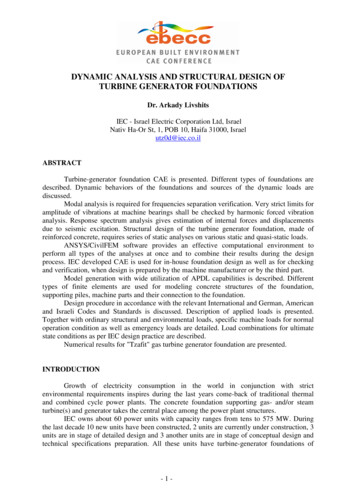
1.4 (SW DL) 1.6 LL 1.6 TE 1.6 (ST NT) 1.4 CB1.4 (SW DL) 1.6 LL 1.6 TE 1.6 (ST NT) 1.4 TB1.4 (SW DL) 1.6 LL 1.6 TE 1.6 (ST NT) 1.4*1.7 SC1.4 (SW DL) 1.2 LL 1.2 (ST NT NP) 1.2 W1.4 (SW DL) 1.4 W1.2 (SW DL) 1.4 W1.0 (SW DL) 1.0 LL 1.0 TE 1.0 (ST NT NP) 1.0 EQ1.0 (SW DL) 1.0 EQ1.4 SW 1.6 CS1.2 (SW DL) 1.6 SLLoad factor consistent with a live load applies for normal operation loads and foremergency loads that may occur from time to time during the machine life. Load factorconsistent with a dead load applies for emergency loads of catastrophic character CB, TB, SCthat have a very low probability of occurrence during the life of the machine. In contrast tonormal operation loads, the emergency loads are not considered acting concurrently withother emergency loads and with accidental environmental loads.The required amount of reinforcement is calculated by CivilFEM standard procedure.CALCULATION EXAMPLE"Tzafit" gas turbine generator foundation (Fig. 4) is of pedestal type. The base mat of2.0 m thickness has a length of 38.0 m and width varies from 11.0 to 16.0 m. Three pedestalssupporting gas turbine frame and exhaust diffuser have a height of 2.85 m and thicknessvaries from 0.75 to 2.0 m. Five connected vertical walls supporting generator have a height ofabout 4.7 m and thickness varies from 0.6 to 1.6 m. Center line of the rotor is located atelevation 5.4 m above top of the base mat. The base mat is supported by 55 piles of 0.8 mdiameter and of 22 m length arranged in diamond grid.Figure 4: "Tzafit" Gas Turbine Generator Foundation-9-
Equipment weight is about 950 tons when foundation self-weight is approximately3000 tons, that provides machine-to-foundation mass ratio less than 1:3.Finite-element model consists of 4200 SHELL63 elements, 165 COMBIN14 elementsand 50 MASS21 elements (Fig. 5). Total number of 37 modes has been extracted. First 3modes are the rigid body modes in horizontal plane with frequencies 2.76 to 3.10 Hz. It givesa good correlation with the single-degree-of-freedom model frequency estimation of 2.90 Hz.The first significant flexural mode (5th mode in full set) is presented on Figure 6.1ELEMENTSJUN 20 200516:16:07YZXTzafit Gas Turbine Generator FoundationFigure 5: "Tzafit" GTGF Finite Element Model1NODAL SOLUTIONSTEP 1SUB 5FREQ 5.991USUM(AVG)RSYS 0DMX .079658SMX .079658JUN 20 08851.026553.044254.061956.079658Tzafit Gas Turbine Generator FoundationFigure 6: "Tzafit" GTGF 5th Natural Mode of Vibration- 10 -
Rotor unbalance forces P1 P2 4.3 tons at the generator collector-end ( P1 ) andturbine-end ( P2 ) bearings and P3 P4 6.6 tons at the turbine forward- ( P3 ) and aft- ( P4 )bearings have been provided by manufacturer. Results of dynamic analysis for horizontalloads applied in counter-phase are presented on Figure 7.Figure 7: "Tzafit" GTGF Vibration Amplitudes at Bearing under Horizontal UnbalanceForces applied in Counter-Phase. Damping 0.02.CONCLUSIONSANSYS/CivilFEM software provides an efficient tool for dynamic analysis andstructural design of the turbine-generator foundations. Analyses features and design procedurehave been described in details. Developed turbine-generator foundation CAE is extensivelyused in IEC design practice. Example of the real project has been presented.REFERENCES[1][2][3][4]Bowels, J.E., "Foundation Analysis and Design", 5th Edition, McGraw-Hill, 1996Whitman, R.V., "Soil-Structure Interaction", Seismic Design for Nuclear PowerPlants, MIT, 1969, pp. 245-269Wolf, J.P., "Simple Physical Models for Foundation Dynamics", Dynamic SoilStructure Interaction, Elsevier Science B.V., 1998, pp. 1-70Livshits, A., "Concrete Chimney Analysis and Design: FE Models and ANSYS-basedCAD", ANSYS Conference Proceedings, Pittsburgh, 1998- 11 -
[5][6][7][8][9][10][11][12][13][14]ISO 1940-1 (1993) Mechanical Vibration – Balance Quality Requirements of RigidRotors – Part 1: Determination of Permissible Residual UnbalanceISO 10816-1 (1995) Mechanical Vibration – Evaluation of Machine Vibration byMeasurements on Non-Rotating Parts – Part 1: General GuidelinesISO 10816-2 (2001) Mechanical Vibration – Evaluation of Machine Vibration byMeasurements on Non-Rotating Parts – Part 2: Land-Based Steam Turbines andGenerators in Excess of 50 MWVDI 2056 (1964)Evaluation of Mechanical Vibration of MachinesDIN 4024 Part 1 (1988) Machine Foundations: Flexible Structures SupportingMachines with Rotating MassesACI 351.3R (2004) Foundations for Dynamic EquipmentSI 466 Part 1 (2003) Concrete Code: General PrinciplesSI 413 (1998/2004) Design Provisions for Earthquake Resistance of StructuresSI 414 (1982)Characteristic Loads in Buildings: Wind LoadsZaslavsky, Y., Gitterman, Y., Shapira, A., "Site Response Estimations in Israel usingWeak Motion Measurements", Proceeding of the 5th International Conference onSeismic Zonation, Nice, 1995, pp.1713-1722- 12 -
design of the TGF. Dynamic response spectrum analysis gives an estimation of internal forces and displacements due to seismic excitation. The structural design of the turbine-generator foundation made of reinforced concrete requires series of static analyses on various static and quasi-static loads.