Transcription
Nexus 9000 Cloud Scale ASIC NX-OS SPANto-CPU ProcedureContentsIntroductionBackground InformationApplicable HardwarePrerequisitesRequirementsComponents UsedCaveats and Limitations50 kbps Default Hardware Rate LimiterSPAN-to-CPU Hardware Rate Limiter Allowed Counter is not SupportedControl Plane-Generated Packets do not Appear in TX SPAN-to-CPU Monitor SessionsCisco Nexus 9000 Cloud Scale SPAN-to-CPU ProcedureStep 1. Confirm Sufficient Resources for the New SPAN SessionStep 2. Configure SPAN-to-CPU Monitor SessionStep 3. Verify SPAN-to-CPU Monitor Session is UpStep 4. View Replicated Packets in the Control PlaneStep 5. Administratively Shut Down the SPAN-to-CPU Monitor SessionStep 6. Remove SPAN-to-CPU Monitor Session Configuration (Optional)Analyze the Results of a SPAN-to-CPU Packet CaptureRelated InformationIntroductionThis document describes the steps used to perform a Switched Port Analyzer (SPAN)-to-CPUpacket capture on a series of Cisco Nexus 9000 Cloud Scale ASIC modules. This document alsodescribes common caveats encountered when using a SPAN-to-CPU packet capture totroubleshoot packet flow through a Cisco Nexus 9000 Cloud Scale series switch.Background InformationA SPAN-to-CPU packet capture allows network administrators to quickly and easily validatewhether specific packets ingress and egress a Cisco Nexus 9000 Cloud Scale series switch.Similarly to a normal SPAN or Encapsulated Remote SPAN (ERSPAN) session, a SPAN-to-CPUmonitor session involves the definition of one or more source interfaces and traffic directions. Anytraffic that matches the direction (TX, RX, or both) defined on a source interface is replicated to thecontrol plane of the Cisco Nexus 9000 device. This replicated traffic can be filtered and analyzedwith the use of the Ethanalyzer control plane packet capture utility or saved to a local storagedevice for later review.This feature is intended for temporary usage while troubleshooting packet flow through CiscoNexus 9000 series switches. Cisco strongly recommends that SPAN-to-CPU monitor sessions are
administratively shut down or removed when not actively used for troubleshooting a packet flowissue. Failure to do so might result in performance degradation for replicated traffic in the networkand increased CPU utilization of the Cisco Nexus 9000 series switch.Applicable HardwareThe procedure covered in this document is applicable to this hardware only: Nexus 9200/9300 Fixed Switches s 9500 Modular Switch Line Cards quisitesRequirementsCisco recommends that you understand the basics of the Ethernet Switched Port Analyzer (SPAN)feature on the Cisco Nexus 9000 series switches. For information about this feature, refer to thefollowing documents: Cisco Nexus 9000 Series NX-OS System Management Configuration Guide, Release 9.3(x)Cisco Nexus 9000 Series NX-OS System Management Configuration Guide, Release 9.2(x)Cisco Nexus 9000 Series NX-OS System Management Configuration Guide, Release7.0(3)I7(x)Components UsedThe information in this document is based on Cisco Nexus 9000 series switches with the CloudScale ASIC running NX-OS software release 9.3(3).The information in this document was created from devices in a specific lab environment. All of thedevices used in this document started with a cleared (default) configuration. If your network is live,make sure that you understand the potential impact of any command.Caveats and LimitationsSPAN-to-CPU monitor sessions have some caveats and limitations to be aware of whentroubleshooting packet flows. This document will cover some commonly-encountered caveats. Fora full list of guidelines and limitations, refer to the following documents: Cisco Nexus 9000 Series NX-OS System Management Configuration Guide, Release 9.3(x)
Cisco Nexus 9000 Series NX-OS System Management Configuration Guide, Release 9.2(x)Cisco Nexus 9000 Series NX-OS System Management Configuration Guide, Release7.0(3)I7(x)50 kbps Default Hardware Rate LimiterBy default, Cisco Nexus 9000 series switches limit the rate of traffic replicated to the control planethrough a SPAN-to-CPU monitor session to 50 kbps. This rate limiting is performed at the CloudScale ASIC/forwarding engine and is a self-protection mechanism to ensure the control plane ofthe device is not overwhelmed with replicated traffic.The show hardware rate-limiter span command can be used to view the current setting of theSPAN-to-CPU monitor session rate limiter.N9K# show hardware rate-limiter spanUnits for Config: kilo bits per second Allowed, Dropped & Total: aggregated bytes since lastclear counters Module: 1 R-L Class ConfigAllowedDroppedTotal ---------------- ---------- -------------------- -------------------- -------------------- span500 0 0If replicated traffic is dropped by the hardware rate-limiter, then the Dropped column will be a nonzero value, as shown in the output below:N9K# show hardware rate-limiter spanUnits for Config: kilo bits per second Allowed, Dropped & Total: aggregated bytes since lastclear counters Module: 1 R-L Class Config Allowed DroppedTotal ---------------- ---------- -------------------- -------------------- -------------------- span50 0 499136499136The SPAN-to-CPU monitor session hardware rate limiter can be changed with the hardware ratelimiter span {kbps} global configuration command, as shown in the output below.N9K# configure terminalEnter configuration commands, one per line. End with CNTL/Z. N9K-1(config)# hardware ratelimiter span 250N9K-1(config)# endN9K# show running-config inc rate-limiterhardware rate-limiter span 250 N9K# show hardware rate-limiter spanUnits for Config: kilo bits per second Allowed, Dropped & Total: aggregated bytes since lastclear counters Module: 1 R-L Class ConfigAllowedDroppedTotal ---------------- ---------- -------------------- -------------------- -------------------- span2500 0 0Caution: Cisco does not recommend modifying the SPAN-to-CPU monitor session hardwarerate limiter away from its default value of 50 kbps unless explicitly instructed to do so byCisco TAC. Increasing this rate limiter to a high value can cause increased CPU utilizationand control plane instability on the Cisco Nexus 9000 series switch, which could cause asignificant impact on production traffic.SPAN-to-CPU Hardware Rate Limiter Allowed Counter is not Supported
The output of the show hardware rate-limiter span command contains an Allowed counter. Onother hardware rate limiters, this counter indicates how many bytes successfully pass through thehardware rate limiter. However, the Allowed counter for the SPAN-to-CPU hardware rate limiterdoes not increment due to a software limitation. An example of this is shown in the output below:N9K# show hardware rate-limiter spanUnits for Config: kilo bits per secondAllowed, Dropped & Total: aggregated bytes since last clear countersModule: 1R-L Class Config AllowedDroppedTotal ---------------- ---------- -------------------- -------------------- -------------------- span 50 0499136499136This software limitation affects all NX-OS software releases and is documented throughCSCva37512.In order to determine how much traffic has been replicated to the control plane of a Nexus 9000device configured with an active SPAN-to-CPU monitor session, use the show system internalaccess-list tcam ingress region span command. An example of the filtered output of theaforementioned command that shows relevant packet and byte counters is shown below.N9K# show system internal access-list tcam ingress region span include pkts: snip pkts: 56582127, bytes: 4119668263Control Plane-Generated Packets do not Appear in TX SPAN-to-CPU MonitorSessionsPackets created by the control plane and transmitted out of a source interface for a SPAN-to-CPUmonitor session will not be captured by the SPAN-to-CPU monitor session. These packets willegress the interface correctly, but cannot be captured through a SPAN-to-CPU monitor session onthe same device where the packet is generated.For example, consider a Cisco Nexus 9000 series device where Ethernet1/1 is an L3/routedinterface connected to another router. OSPF process 1 is activated on Ethernet1/1, which is theonly OSPF-activated interface on the Cisco Nexus 9000 device.N9K# show running-config ospf!Command: show running-config ospf !Running configuration last done at: Wed Feb 26 16:16:30 2020!Time: Wed Feb 26 16:16:37 2020 version 9.3(3) Bios:version 05.39 feature ospf router ospf 1interface Ethernet1/1 ip router ospf 1 area 0.0.0.0 N9K# show ip ospf interface briefOSPF Process ID 1 VRF default Total number of interface: 1 Interface ID Area Cost StateNeighbors Status Eth1/1 1 0.0.0.0 4 DR 0 upThe Ethanalyer control plane packet capture utility shows that OSPF Hello messages aregenerated by the control plane of the device once every 10 seconds.N9K# ethanalyzer local interface inband display-filter ospf limit-captured-frames 0Capturing on inband 2020-02-26 16:19:13.041255 192.168.1.1 - 224.0.0.5 OSPF Hello Packet2020-02-26 16:19:22.334692 192.168.1.1 - 224.0.0.5 OSPF Hello Packet
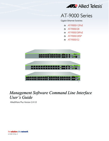
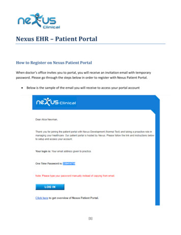
2020-02-26 16:19:31.568034 192.168.1.1 - 224.0.0.5 OSPF Hello Packet C 3 packets capturedHowever, an egress/TX SPAN-to-CPU on the Ethernet1/1 interface does not show these OpenShortest Path First (OSPF) Hello packets transmitted on this interface after 60 seconds of time.N9K# show running-config monitor!Command: show running-configmonitor !Running configuration last done at: Wed Feb 26 16:20:482020 !Time: Wed Feb 26 16:20:51 2020 version 9.3(3) Bios:version 05.39 monitor session 1 sourceinterface Ethernet1/1 tx destination interface sup-eth0 no shut N9K# show monitorSession StateReasonDescription------- ----------- ---------------------- -------------------------------1upThe session is upN9K# ethanalyzer local interface inband mirror display-filter ospf autostop duration 60Capturing on inband0 packets capturedIn order to verify whether packets generated by the control plane of a Cisco Nexus 9000 deviceare transmitted out of a specific interface, Cisco recommends using a packet capture utility on theremote device connected to the interface.Cisco Nexus 9000 Cloud Scale SPAN-to-CPU ProcedureConsider the following topology:An Internet Control Message Protocol (ICMP) packet sourced from server SRV01 in VLAN 10(192.168.10.10) is destined for the VLAN 10 gateway 192.168.10.1. A SPAN-to-CPU monitorsession will be used to confirm that this ICMP packet traverses device N9K (a Cisco Nexus93180YC-EX that runs NX-OS software release 9.3(3)), which acts as a Layer 2 switch thatconnects SRV01 to AGGSW in VLAN 10.Step 1. Confirm Sufficient Resources for the New SPAN SessionCisco Nexus 9000 series switches with the Cloud Scale ASIC that run NX-OS software support amaximum of four active SPAN or ERSPAN sessions per ASIC/forwarding engine. Furthermore, ifthe first three SPAN or ERSPAN sessions are configured with bidirectional (TX and RX) sourceinterfaces, the source interface of the fourth SPAN or ERSPAN session must be an ingress/RXsource.
Before you configure a SPAN-to-CPU monitor session, verify the quantity of other SPAN orERSPAN sessions currently configured on the device. This can be done with the show runningconfig monitor and show monitor commands. The example below shows the output of bothcommands when no other SPAN or ERSPAN sessions are configured on the device.N9K# show running-config monitor!Command: show running-configmonitor !Running configuration last done at: Tue Feb 25 20:34:042020 !Time: Tue Feb 25 20:34:06 2020 version 9.3(3) Bios:version 07.66 N9K# show monitorNote: No sessions configuredNote: Additional information about the maximum number of SPAN/ERSPAN sessions andother limitations can be found in the Cisco Nexus 9000 Series NX-OS Verified ScalabilityGuide for NX-OS Software Release 9.3(3).Step 2. Configure SPAN-to-CPU Monitor SessionThe key configuration element that defines a SPAN-to-CPU monitor session is a destinationinterface of "sup-eth0", which is the supervisor's inband interface. The example below shows theconfiguration of a SPAN-to-CPU monitor session where the ingress/RX packets of Ethernet1/10are replicated to the supervisor of the Cisco Nexus 9000 series switch.N9K# configure terminalEnter configuration commands, one per line. End with CNTL/Z.N9K-1(config)# monitor session 1N9K-1(config-monitor)# source interface Ethernet1/10 rxN9K-1(config-monitor)# destination interface sup-eth0N9K-1(config-monitor)# no shutN9K-1(config-monitor)# endN9K#Step 3. Verify SPAN-to-CPU Monitor Session is UpUse the show running-config monitor and show monitor commands in order to verify that theSPAN-to-CPU monitor session is configured and operational. The configuration of the SPAN-toCPU monitor session can be verified through the output of the show running-config monitorcommand, as shown in the example below.N9K# show running-config monitor!Command: show running-configmonitor !Running configuration last done at: Tue Feb 25 20:47:502020 !Time: Tue Feb 25 20:49:35 2020 version 9.3(3) Bios:version 07.66 monitor session 1 sourceinterface Ethernet1/10 rx destination interface sup-eth0 no shutThe operational state of the SPAN-to-CPU monitor session can be verified through the output ofthe show monitor command. The output should report that the state of the SPAN-to-CPU monitorsession is "up" with a reason of "The session is up", as shown in the example below.N9K# show monitorSession State Reason Description - - - - - - - - - - - - - - - - - - - - - - - - - - - - - - - - - - - - - - - - - - - - - - - - - - - - - - - - - - - - - - - - - - - - - - - 1 up The sessionis up
Step 4. View Replicated Packets in the Control PlaneThe Ethanalyer control plane packet capture utility can be used to view traffic replicated to thecontrol plane of the Cisco Nexus 9000 device. The mirror keyword in the Ethanalyzer commandfilters traffic such that only traffic replicated by a SPAN-to-CPU monitor session is shown.Ethanalyzer capture and display filters can be used to further limit the traffic displayed. Additionalinformation about useful Ethanalyzer capture and display filters can be found in the Ethanalyzer onNexus 7000 Troubleshooting Guide. Note that while this document was written for the CiscoNexus 7000 platform, it is mostly applicable to the Cisco Nexus 9000 platform as well.An example of the usage of the Ethanalyzer control plane packet capture utility to filter trafficreplicated by a SPAN-to-CPU monitor session is shown below. Note that the mirror keyword isused, as well as a display filter defining ICMP packets sourced from or destined to 192.168.10.10(the IP address of SRV01 in the aforementioned topology).N9K# ethanalyzer local interface inband mirror display-filter "icmp && ip.addr 192.168.10.10"limit-captured-frames 0Capturing on inband2020-02-25 21:01:07.592838 192.168.10.10 - 192.168.10.1 ICMP Echo (ping) request 2020-02-2521:01:08.046682 192.168.10.10 - 192.168.10.1 ICMP Echo (ping) request 2020-02-2521:01:08.047720 192.168.10.10 - 192.168.10.1 ICMP Echo (ping) request 2020-02-2521:01:08.527646 192.168.10.10 - 192.168.10.1 ICMP Echo (ping) request 2020-02-2521:01:08.528659 192.168.10.10 - 192.168.10.1 ICMP Echo (ping) request 2020-02-2521:01:08.529500 192.168.10.10 - 192.168.10.1 ICMP Echo (ping) request 2020-02-2521:01:08.530082 192.168.10.10 - 192.168.10.1 ICMP Echo (ping) request 2020-02-2521:01:08.530659 192.168.10.10 - 192.168.10.1 ICMP Echo (ping) request 2020-02-2521:01:08.531244 192.168.10.10 - 192.168.10.1 ICMP Echo (ping) request C 9 packets capturedNote: Use the Control-C key combination in order to exit the Ethanalyzer control planepacket capture utility.One can view detailed information about this traffic by including the detail keyword in theEthanalyzer command. An example of this for a single ICMP Echo Request packet is shownbelow.N9K# ethanalyzer local interface inband mirror display-filter "icmp && ip.addr 192.168.10.10"limit-captured-frames 0 detailCapturing on inband Frame 2 (114 bytes on wire, 114 bytes captured) Arrival Time: Feb 25, 202021:56:40.497381000 [Time delta from previous captured frame: 1.874113000 seconds] [Time deltafrom previous displayed frame: 1.874113000 seconds] [Time since reference or first frame:1.874113000 seconds] Frame Number: 2 Frame Length: 114 bytes Capture Length: 114 bytes [Frame ismarked: False] [Protocols in frame: eth:ip:icmp:data] Ethernet II, Src: 30:8b:b2:37:6b:66(30:8b:b2:37:6b:66), Dst: 28:ac:9e:d6:07:47 (28:ac:9e:d6:07:47) Destination: 28:ac:9e:d6:07:47(28:ac:9e:d6:07:47) Address: 28:ac:9e:d6:07:47 (28:ac:9e:d6:07:47) . .0 . . . . IG bit: Individual address (unicast) . .0. . . . . LG bit: Globally uniqueaddress (factory default) Source: 30:8b:b2:37:6b:66 (30:8b:b2:37:6b:66) Address:30:8b:b2:37:6b:66 (30:8b:b2:37:6b:66) . .0 . . . . IG bit: Individual address(unicast) . .0. . . . . LG bit: Globally unique address (factory default) Type: IP (0x0800) Internet Protocol, Src: 192.168.10.10 (192.168.10.10), Dst: 192.168.10.1(192.168.10.1) Version : 4 Header length: 20 bytes Differentiated Services Field: 0x00 (DSCP0x00: Default; ECN: 0x00) 0000 00. Differentiated Services Codepoint: Default (0x00) .0. ECN-Capable Transport (ECT): 0 . .0 ECN-CE: 0 Total Length: 100 Identification:0x00e1 (225) Flags: 0x00 0. Reserved bit: Not Set .0. Don't fragment: Not Set .0 Morefragments: Not Set Fragment offset: 0 Time to live: 254 Protocol: ICMP (0x01) Header checksum :0x265c [correct] [Good: True] [Bad : False] Source: 192.168.10.10 (192.168.10.10) Destination:192.168.10.1 (192.168.10.1) Internet Control Message Protocol Type : 8 (Echo (ping) request)
Code: 0 () Checksum : 0xf1ed [correct] Identifier: 0x0004 Sequence number: 0 (0x0000) Data (72bytes) 0000 00 00 00 00 ed 9e 9e b9 ab cd ab cd ab cd ab cd . 0010 ab cd ab cd abcd ab cd ab cd ab cd ab cd ab cd . 0020 ab cd ab cd ab cd ab cd ab cd ab cd ab cdab cd . 0030 ab cd ab cd ab cd ab cd ab cd ab cd ab cd ab cd .0040 ab cd ab cd ab cd ab cd . Data: Length: 72] C 1 packet capturedStep 5. Administratively Shut Down the SPAN-to-CPU Monitor SessionUse the shut configuration command within the context of the SPAN-to-CPU monitor session togracefully shut down the SPAN-to-CPU monitor session and stop replicating traffic to the CiscoNexus 9000 device's control plane.N9K# configure terminalEnter configuration commands, one per line. End with CNTL/Z.N9K-1(config)# monitor session 1N9K-1(config-monitor)# shutN9K-1(config-monitor)# endN9K#Verify the operational state of the SPAN-to-CPU monitor session with the show monitorcommand. The operational state of the SPAN-to-CPU monitor session should show as "down"with a reason of "Session admin shut", as shown in the example below:N9K# show monitorSession State Reason Description - - - - - - - - - - - - - - - - - - - - - - - - - - - - - - - - - - - - - - - - - - - - - - - - - - - - - - - - - - - - - - - - - - - - - - - 1 down Sessionadmin shutStep 6. Remove SPAN-to-CPU Monitor Session Configuration (Optional)If desired, remove the SPAN-to-CPU monitor session configuration with the no monitor session{id} configuration command. An example of this is shown in the output below.N9K# configure terminalEnter configuration commands, one per line . End with CNTL/Z. N9K-1(config)# no monitor session1N9K-1(config)# endVerify that the SPAN-to-CPU monitor session configuration has been successfully removed withthe show running-config monitor command, as shown in the example below.N9K# show running-config monitor!Command: show running-configmonitor !Running configuration last done at: Tue Feb 25 21:46:252020 !Time: Tue Feb 25 21:46:29 2020 version 9.3(3) Bios:version 07.66 N9K#Analyze the Results of a SPAN-to-CPU Packet CaptureThe above example of this procedure shows that ICMP Echo Request packets sourced from192.168.10.10 (SRV01) destined to 192.168.10.1 (AGGSW) ingress the Ethernet1/10 interface ofthe Cisco Nexus 9000 device with a hostname of N9K. This proves that SRV01 sends this trafficout of its network interface card. This also proves that the ICMP Echo Request packet progressesfar enough into the Cisco Cloud Scale ASIC's forwarding pipeline for it to be replicated to the
control plane of the device.However, this does not prove that the Cisco Nexus 9000 device forwards the ICMP Echo Requestpacket out of Ethernet1/1 towards AGGSW. Further troubleshooting needs to be performed tovalidate whether the packet is forwarded out of Ethernet1/1 towards AGGSW. In order oftrustworthiness:1. If the remote device of the expected egress interface (Ethernet1/1 of N9K in the example) is aCisco Nexus 9000 series device with a Cloud-Scale ASIC, you can perform an ingress/RX SPANto-CPU monitor session on the remote device (Eth1/1 of AGGSW in the example previously). If theremote device of the expected egress interface is not a Cisco Nexus 9000 series device with aCloud-Scale ASIC, then a SPAN, port mirror, or other similar packet capture on the remote deviceis equivalent.2. Perform an ingress/RX ELAM on the ingress interface (Ethernet1/10 of N9K in the exampleabove) of the Cisco Nexus 9000 device. Additional information about this procedure can be foundin the Nexus 9000 Cloud Scale ASIC NX-OS ELAM Troubleshooting TechNote.3. Perform an egress/TX SPAN-to-CPU on the egress interface of the Cisco Nexus 9000 device(Ethernet1/1 of N9K in the example above).Related Information Cisco Nexus 9000 Series NX-OS Troubleshooting Guide, Release 9.3(x)Cisco Nexus 9000 Series NX-OS Troubleshooting Guide, Release 9.2(x)Cisco Nexus 9000 Series NX-OS Troubleshooting Guide, Release 7.0(3)I7(x)Ethanalyzer on Nexus 7000 Troubleshooting GuideNexus 9000 Cloud Scale ASIC (Tahoe) NX-OS ELAM
Step 6. Remove SPAN-to-CPU Monitor Session Configuration (Optional) Analyze the Results of a SPAN-to-CPU Packet Capture Related Information Introduction This document describes the steps used to perform a Switched Port Analyzer (SPAN)-to-CPU packet capture on a series of Cisco Nexus 9000 Cloud Scale ASIC modules. This document also