Transcription
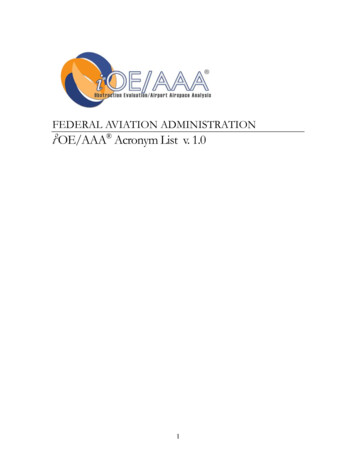
Chapter 7FlightInstrumentsIntroductionIn order to safely fly any aircraft, a pilot must understandhow to interpret and operate the flight instruments. Thepilot also needs to be able to recognize associated errors andmalfunctions of these instruments. This chapter addresses thepitot-static system and associated instruments, the vacuumsystem and related instruments, gyroscopic instruments, andthe magnetic compass. When a pilot understands how eachinstrument works and recognizes when an instrument ismalfunctioning, he or she can safely utilize the instrumentsto their fullest potential.Pitot-Static Flight InstrumentsThe pitot-static system is a combined system that utilizes thestatic air pressure, and the dynamic pressure due to the motionof the aircraft through the air. These combined pressures areutilized for the operation of the airspeed indicator (ASI),altimeter, and vertical speed indicator (VSI). [Figure 7-1]7-1
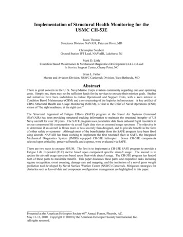
Pitot-static system and instrumentsAirspeed indicator (ASI)Vertical speed indicator (VSI)Altimeter29.829.930.0Pressure chamberStatic portStatic chamberBaffle platePitot tubeDrain holeRam airStatic holeHeater (35 watts)Heater (100 watts)Pitot heater switchAlternate static sourceFigure 7-1. Pitot-static system and instruments.Impact Pressure Chamber and LinesThe pitot tube is utilized to measure the total combinedpressures that are present when an aircraft moves throughthe air. Static pressure, also known as ambient pressure, isalways present whether an aircraft is moving or at rest. It issimply the barometric pressure in the local area. Dynamicpressure is present only when an aircraft is in motion;therefore, it can be thought of as a pressure due to motion.Wind also generates dynamic pressure. It does not matter ifthe aircraft is moving through still air at 70 knots or if theaircraft is facing a wind with a speed of 70 knots, the samedynamic pressure is generated.When the wind blows from an angle less than 90 off thenose of the aircraft, dynamic pressure can be depicted on theASI. The wind moving across the airfoil at 20 knots is thesame as the aircraft moving through calm air at 20 knots.The pitot tube captures the dynamic pressure, as well as thestatic pressure that is always present.The pitot tube has a small opening at the front which allowsthe total pressure to enter the pressure chamber. The totalpressure is made up of dynamic pressure plus static pressure.In addition to the larger hole in the front of the pitot tube,there is a small hole in the back of the chamber whichallows moisture to drain from the system should the aircraftenter precipitation. Both openings in the pitot tube need to7-2be checked prior to flight to insure that neither is blocked.Many aircraft have pitot tube covers installed when they sitfor extended periods of time. This helps to keep bugs andother objects from becoming lodged in the opening of thepitot tube.The one instrument that utilizes the pitot tube is the ASI. Thetotal pressure is transmitted to the ASI from the pitot tube’spressure chamber via a small tube. The static pressure isalso delivered to the opposite side of the ASI which servesto cancel out the two static pressures, thereby leaving thedynamic pressure to be indicated on the instrument. When thedynamic pressure changes, the ASI shows either increase ordecrease, corresponding to the direction of change. The tworemaining instruments (altimeter and VSI) utilize only thestatic pressure which is derived from the static port.Static Pressure Chamber and LinesThe static chamber is vented through small holes to thefree undisturbed air on the side(s) of the aircraft. As theatmospheric pressure changes, the pressure is able to movefreely in and out of the instruments through the small lineswhich connect the instruments into the static system. Analternate static source is provided in some aircraft to providestatic pressure should the primary static source becomeblocked. The alternate static source is normally found insideof the flight deck. Due to the venturi effect of the air flowing
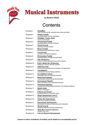
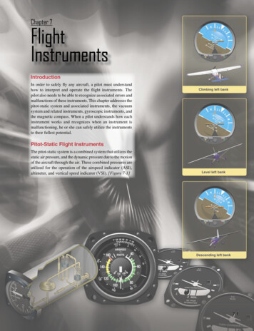
Altimeteraround the fuselage, the air pressure inside the flight deck islower than the exterior pressure.When the alternate static source pressure is used, thefollowing instrument indications are observed:1.The altimeter indicates a slightly higher altitude thanactual.2.The ASI indicates an airspeed greater than the actualairspeed.3.The VSI shows a momentary climb and then stabilizesif the altitude is held constant.Each pilot is responsible for consulting the Aircraft FlightManual (AFM) or the Pilot’s Operating Handbook (POH)to determine the amount of error that is introduced into thesystem when utilizing the alternate static source. In an aircraftnot equipped with an alternate static source, an alternatemethod of introducing static pressure into the system shoulda blockage occur is to break the glass face of the VSI. Thismost likely renders the VSI inoperative. The reason forchoosing the VSI as the instrument to break is that it is theleast important static source instrument for flight.AltimeterThe altimeter is an instrument that measures the height ofan aircraft above a given pressure level. Pressure levelsare discussed later in detail. Since the altimeter is the onlyinstrument that is capable of indicating altitude, this is one ofthe most vital instruments installed in the aircraft. To use thealtimeter effectively, the pilot must understand the operationof the instrument, as well as the errors associated with thealtimeter and how each effect the indication.A stack of sealed aneroid wafers comprise the maincomponent of the altimeter. An aneroid wafer is a sealedwafer that is evacuated to an internal pressure of 29.92 inchesof mercury (29.92 "Hg). These wafers are free to expandand contract with changes to the static pressure. A higherstatic pressure presses down on the wafers and causes themto collapse. A lower static pressure (less than 29.92 "Hg)allows the wafers to expand. A mechanical linkage connectsthe wafer movement to the needles on the indicator face,which translates compression of the wafers into a decreasein altitude and translates an expansion of the wafers into anincrease in altitude. [Figure 7-2]Notice how the static pressure is introduced into the rear ofthe sealed altimeter case. The altimeter’s outer chamber issealed, which allows the static pressure to surround the aneroidwafers. If the static pressure is higher than the pressure in theaneroid wafers (29.92 "Hg), then the wafers are compresseduntil the pressure inside the wafers is equal to the surrounding1,000 ft. pointer100 ft. pointer10,000 ft. pointerAneroid wafersStatic portCrosshatch flagA crosshatched area appears onsome altimeters when displayingan altitude below 10,000 feet MSL.Barometric scale adjustment knobAltimeter setting windowFigure 7-2. Altimeter.static pressure. Conversely, if the static pressure is less thanthe pressure inside of the wafers, the wafers are able to expandwhich increases the volume. The expansion and contractionof the wafers moves the mechanical linkage, which drives theneedles on the face of the ASI.Principle of OperationThe pressure altimeter is an aneroid barometer that measuresthe pressure of the atmosphere at the level where the altimeteris located, and presents an altitude indication in feet. Thealtimeter uses static pressure as its source of operation.Air is denser at sea level than aloft—as altitude increases,atmospheric pressure decreases. This difference in pressureat various levels causes the altimeter to indicate changes inaltitude.The presentation of altitude varies considerably betweendifferent types of altimeters. Some have one pointer whileothers have two or more. Only the multipointer type isdiscussed in this handbook. The dial of a typical altimeteris graduated with numerals arranged clockwise from zeroto nine. Movement of the aneroid element is transmittedthrough gears to the three hands that indicate altitude. Theshortest hand indicates altitude in tens of thousands of feet,the intermediate hand in thousands of feet, and the longesthand in hundreds of feet.7-3
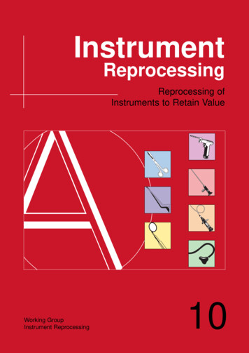
This indicated altitude is correct, however, only when the sealevel barometric pressure is standard (29.92 "Hg), the sea levelfree air temperature is standard ( 15 degrees Celsius ( C) or59 degrees Fahrenheit ( F)), and the pressure and temperaturedecrease at a standard rate with an increase in altitude.Adjustments for nonstandard pressures are accomplished bysetting the corrected pressure into a barometric scale locatedon the face of the altimeter. The barometric pressure window issometimes referred to as the Kollsman window; only after thealtimeter is set does it indicate the correct altitude. The word“correct” will need to be better explained when referring totypes of altitudes, but is commonly used in this case to denotethe approximate altitude above sea level. In other words, theindicated altitude refers to the altitude read off of the altitudewhich is uncorrected, after the barometric pressure settingis dialed into the Kollsman window. The additional types ofaltitudes are further explained later.Effect of Nonstandard Pressure and TemperatureIt is easy to maintain a consistent height above ground if thebarometric pressure and temperature remain constant, butthis is rarely the case. The pressure temperature can changebetween takeoff and landing even on a local flight. If thesechanges are not taken into consideration, flight becomesdangerous.If altimeters could not be adjusted for nonstandard pressure, ahazardous situation could occur. For example, if an aircraft isflown from a high pressure area to a low pressure area withoutadjusting the altimeter, a constant altitude will be displayed,but the actual height of the aircraft above the ground wouldbe lower then the indicated altitude. There is an old aviationaxiom: “GOING FROM A HIGH TO A LOW, LOOK OUT5,000 foo4,000t pressurre levot preselsure levelpressure le1,000 foot pressureSea levelvellevel30 CFigure 7-3. Effects of nonstandard temperature on an altimeter.7-4Adjustments to compensate for nonstandard pressure do notcompensate for nonstandard temperature. Since cold air isdenser than warm air, when operating in temperatures that arecolder than standard, the altitude is lower than the altimeterindication. [Figure 7-3] It is the magnitude of this “difference”that determines the magnitude of the error. It is the differencedue to colder temperatures that concerns the pilot. When flyinginto a cooler air mass while maintaining a constant indicatedaltitude, true altitude is lower. If terrain or obstacle clearanceis a factor in selecting a cruising altitude, particularly inmountainous terrain, remember to anticipate that a colderthan-standard temperature places the aircraft lower than thealtimeter indicates. Therefore, a higher indicated altitude maybe required to provide adequate terrain clearance. A variationof the memory aid used for pressure can be employed:“FROM HOT TO COLD, LOOK OUT BELOW.” When theair is warmer than standard, the aircraft is higher than theelressu2,000 footMany altimeters do not have an accurate means of beingadjusted for barometric pressures in excess of 31.00 inchesof mercury ("Hg). When the altimeter cannot be set to thehigher pressure setting, the aircraft actual altitude will behigher than the altimeter indicates. When low barometricpressure conditions occur (below 28.00), flight operationsby aircraft unable to set the actual altimeter setting are notrecommended.e levfoot p3,000 foBELOW.” Conversely, if an aircraft is flown from a lowpressure area to a high pressure area without an adjustmentof the altimeter, the actual altitude of the aircraft is higherthan the indicated altitude. Once in flight, it is important tofrequently obtain current altimeter settings en route to ensureterrain and obstruction clearance.15 C0 C
altimeter indicates. Altitude corrections for temperature canbe computed on the navigation computer.Extremely cold temperatures will also affect altimeterindications. Figure 7-4, which was derived from ICAOformulas, indicates how much error can exist when thetemperature is extremely cold.20 1010101010202020202030020203030404050506090 120 170 230 280-102030405060708090 100 150 200 290 390 490-203050607090 100 120 130 140 210 280 420 570 710-30406080 100 120 140 150 170 190 280 380 570 760 950-405080 100 120 150 170 190 220 240 360 480 720 970 1210-506090 120 150 180 210 240 270 300 450 590 890 1190 ReportedTemp 0 CHeight Above Airport in Feet40608090Figure 7-4. Look at the chart using a temperature of –10 C andthe aircraft altitude is 1,000 feet above the airport elevation. Thechart shows that the reported current altimeter setting may placethe aircraft as much as 100 feet below the altitude indicated bythe altimeter.Setting the AltimeterMost altimeters are equipped with a barometric pressuresetting window (or Kollsman window) providing a means toadjust the altimeter. A knob is located at the bottom of theinstrument for this adjustment.To adjust the altimeter for variation in atmospheric pressure,the pressure scale in the altimeter setting window, calibratedin inches of mercury ("Hg) and/or millibars (mb), is adjustedto match the given altimeter setting. Altimeter setting isdefined as station pressure reduced to sea level, but, analtimeter setting is accurate only in the vicinity of thereporting station. Therefore, the altimeter must be adjusted asthe flight progresses from one station to the next. Air trafficcontrol (ATC) will advise when updated altimeter settingsare available. If a pilot is not utilizing ATC assistance,local altimeter settings can be obtained by monitoring localautomated weather observing system/automated surfaceobservation system (AWOS/ASOS) or automatic terminalinformation service (ATIS) broadcasts.Many pilots confidently expect the current altimeter settingwill compensate for irregularities in atmospheric pressure atall altitudes, but this is not always true. The altimeter settingbroadcast by ground stations is the station pressure correctedto mean sea level. It does not account for the irregularities athigher levels, particularly the effect of nonstandard temperature.If each pilot in a given area is using the same altimeter setting,each altimeter should be equally affected by temperature andpressure variation errors, making it possible to maintain thedesired vertical separation between aircraft. This does notguarantee vertical separation though. It is still imperative tomaintain a regimented visual scan for intruding air traffic.When flying over high, mountainous terrain, certain atmosphericconditions cause the altimeter to indicate an altitude of 1,000feet or more higher than the actual altitude. For this reason, agenerous margin of altitude should be allowed—not only forpossible altimeter error, but also for possible downdrafts thatmight be associated with high winds.To illustrate the use of the altimeter setting system, follow aflight from Dallas Love Field, Texas, to Abilene MunicipalAirport, Texas, via Mineral Wells. Before taking off fromLove Field, the pilot receives a current altimeter setting of29.85 "Hg from the control tower or ATIS, and sets this valuein the altimeter setting window. The altimeter indicationshould then be compared with the known airport elevation of487 feet. Since most altimeters are not perfectly calibrated,an error may exist.When over Mineral Wells, assume the pilot receives a currentaltimeter setting of 29.94 "Hg and sets this in the altimeterwindow. Before entering the traffic pattern at AbileneMunicipal Airport, a new altimeter setting of 29.69 "Hgis received from the Abilene Control Tower, and set in thealtimeter setting window. If the pilot desires to fly the trafficpattern at approximately 800 feet above the terrain, and thefield elevation of Abilene is 1,791 feet, an indicated altitude of2,600 feet should be maintained (1,791 feet 800 feet 2,591feet, rounded to 2,600 feet).The importance of properly setting the altimeter cannot beoveremphasized. Assume the pilot did not adjust the altimeterat Abilene to the current setting and continued using theMineral Wells setting of 29.94 "Hg. When entering the Abilenetraffic pattern at an indicated altitude of 2,600 feet, the aircraftwould be approximately 250 feet below the proper trafficpattern altitude. Upon landing, the altimeter would indicateapproximately 250 feet higher than the field elevation.Mineral Wells altimeter setting29.94Abilene altimeter setting29.69Difference0.25(Since 1 inch of pressure is equal to approximately 1,000 feetof altitude, 0.25 x 1,000 feet 250 feet.)7-5
When determining whether to add or subtract the amountof altimeter error, remember that, when the actual pressureis lower than what is set in the altimeter window, the actualaltitude of the aircraft is lower than what is indicated on thealtimeter.The following is another method of computing the altitudedeviation. Start by subtracting the current altimeter setting from29.94 "Hg. Always remember to place the original setting asthe top number. Then subtract the current altimeter setting.Mineral Wells altimeter setting29.94Abilene altimeter setting29.6929.94 – 29.69 Difference0.25(Since 1 inch of pressure is equal to approximately 1,000 feetof altitude, 0.25 x 1,000 feet 250 feet.) Always subtract thenumber from the indicated altitude.2,600 – 250 2,350Now, try a lower pressure setting. Adjust from altimetersetting 29.94 to 30.56 "Hg.Mineral Wells altimeter setting29.94Altimeter setting30.5629.94 – 30.56 Difference–0.62(Since 1 inch of pressure is equal to approximately 1,000 feetof altitude, 0.62 x 1,000 feet 620 feet.) Always subtractthe number from the indicated altitude.2,600 – (–620) 3,220The pilot will be 620 feet high.Notice the difference is a negative number. Starting with thecurrent indicated altitude of 2,600 feet, subtracting a negativenumber is the same as adding the two numbers. By utilizingthis method, a pilot should be able to better understand whatis happening with the aircraft’s altitude. This method alwaysyields the correct result and tells a pilot what the altitude isand the direction. (The implications of not understandingwhere the errors lie and in what direction are important to asafe flight.) If the altitude was lower than actually indicated,an aircraft could be in danger of colliding with an obstacle.This movement is transmitted through mechanical linkageto rotate the pointers.A decrease in pressure causes the altimeter to indicate anincrease in altitude, and an increase in pressure causes thealtimeter to indicate a decrease in altitude. Accordingly, ifthe aircraft is sitting on the ground with a pressure level of29.98 "Hg and the pressure level changes to 29.68 "Hg, thealtimeter would show an increase of approximately 300 feetin altitude. This pressure change is most noticeable when theaircraft is left parked over night. As the pressure falls, thealtimeter interprets this as a climb. The altimeter indicatesan altitude above the actual field elevation. If the barometricpressure setting is reset to the current altimeter setting of29.68 "Hg, then the field elevation is again indicated on thealtimeter.This pressure change is not as easily noticed in flight sinceaircraft fly specific altitudes. The aircraft steadily decreasestrue altitude while the altimeter is held constant through pilotaction as discussed in the previous section.Knowing the aircraft’s altitude is vitally important to apilot. The pilot must be sure that the aircraft is flying highenough to clear the highest terrain or obstruction along theintended route. It is especially important to have accuratealtitude information when visibility is restricted. To clearobstructions, the pilot must constantly be aware of the altitudeof the aircraft and the elevation of the surrounding terrain. Toreduce the possibility of a midair collision, it is essential tomaintain altitude in accordance with air traffic rules.Types of AltitudeAltitude in itself is a relevant term only when it is specificallystated to which type of altitude a pilot is referring to.Normally when the term altitude is used, it is referring toaltitude above sea level since this is the altitude which isused to depict obstacles and airspace, as well as to separateair traffic.Altitude is vertical distance above some point or level used asa reference. There are as many kinds of altitude as there arereference levels from which altitude is measured, and eachmay be used for specific reasons. Pilots are mainly concernedwith five types of altitudes:Altimeter Operation1.There are two means by which the altimeter pointers canbe moved. The first is a change in air pressure, while theother is an adjustment to the barometric scale. When theaircraft climbs or descends, changing pressure within thealtimeter case expands or contracts the aneroid barometer.Indicated altitude—read directly from the altimeter(uncorrected) when it is set to the current altimetersetting.2.True altitude—the vertical distance of the aircraft abovesea level—the actual altitude. It is often expressed asfeet above mean sea level (MSL). Airport, terrain,7-6
and obstacle elevations on aeronautical charts are truealtitudes.3.Absolute altitude—the vertical distance of an aircraftabove the terrain, or above ground level (AGL).4.Pressure altitude—the altitude indicated whenthe altimeter setting window (barometric scale) isadjusted to 29.92 "Hg. This is the altitude above thestandard datum plane, which is a theoretical planewhere air pressure (corrected to 15 C) equals 29.92"Hg. Pressure altitude is used to compute densityaltitude, true altitude, true airspeed (TAS), and otherperformance data.5.Density altitude—pressure altitude correctedfor variations from standard temperature. Whenconditions are standard, pressure altitude and densityaltitude are the same. If the temperature is abovestandard, the density altitude is higher than pressurealtitude. If the temperature is below standard, thedensity altitude is lower than pressure altitude. Thisis an important altitude because it is directly relatedto the aircraft’s performance.A pilot must understand how the performance of the aircraftis directly related to the density of the air. The density ofthe air affects how much power a naturally aspirated engineproduces, as well as how efficient the airfoils are. If there arefewer air molecules (lower pressure) to accelerate throughthe propeller, the acceleration to rotation speed is longerand thus produces a longer takeoff roll, which translates toa decrease in performance.As an example, consider an airport with a field elevationof 5,048 feet MSL where the standard temperature is 5 C.Under these conditions, pressure altitude and density altitudeare the same—5,048 feet. If the temperature changes to30 C, the density altitude increases to 7,855 feet. Thismeans an aircraft would perform on takeoff as though thefield elevation were 7,855 feet at standard temperature.Conversely, a temperature of –25 C would result in a densityaltitude of 1,232 feet. An aircraft would perform much betterunder these conditions.Instrument CheckPrior to each flight, a pilot should examine the altimeter forproper indications in order to verify its validity. To determinethe condition of an altimeter, set the barometric scale to thecurrent reported altimeter setting transmitted by the localautomated flight service station (AFSS) or any other reliablesource, such as ATIS, AWOS, or ASOS. The altimeterpointers should indicate the surveyed field elevation of theairport. If the indication is off more than 75 feet from thesurveyed field elevation, the instrument should be referred toa certificated instrument repair station for recalibration.Vertical Speed Indicator (VSI)The VSI, which is sometimes called a vertical velocityindicator (VVI), indicates whether the aircraft is climbing,descending, or in level flight. The rate of climb or descentis indicated in feet per minute (fpm). If properly calibrated,the VSI indicates zero in level flight. [Figure 7-5]2 3VERTICAL SPEEDTHOUSAND FT PER MINOWN243Figure 7-5. Vertical speed indicator (VSI).Principle of OperationAlthough the VSI operates solely from static pressure, it is adifferential pressure instrument. It contains a diaphragm withconnecting linkage and gearing to the indicator pointer insidean airtight case. The inside of the diaphragm is connecteddirectly to the static line of the pitot-static system. The areaoutside the diaphragm, which is inside the instrument case,is also connected to the static line, but through a restrictedorifice (calibrated leak).Both the diaphragm and the case receive air from the staticline at existing atmospheric pressure. The diaphragm receivesunrestricted air while the case receives the static pressure viathe metered leak. When the aircraft is on the ground or in levelflight, the pressures inside the diaphragm and the instrumentcase are equal and the pointer is at the zero indication. Whenthe aircraft climbs or descends, the pressure inside thediaphragm changes immediately, but due to the meteringaction of the restricted passage, the case pressure remainshigher or lower for a short time, causing the diaphragm tocontract or expand. This causes a pressure differential thatis indicated on the instrument needle as a climb or descent.7-7
a positive rate of climb and then, once a stabilized climb isestablished, a rate of climb can be referenced.AccelerometerI.5 UP023.5 DOWN4I2 3Inlet from static portCalibrated leakAirspeed Indicator (ASI)The ASI is a sensitive, differential pressure gauge whichmeasures and promptly indicates the difference between pitot(impact/dynamic pressure) and static pressure. These twopressures are equal when the aircraft is parked on the groundin calm air. When the aircraft moves through the air, thepressure on the pitot line becomes greater than the pressurein the static lines. This difference in pressure is registered bythe airspeed pointer on the face of the instrument, which iscalibrated in miles per hour, knots (nautical miles per hour),or both. [Figure 7-7]Airspeed indicatorDiaphragmLong leverFigure 7-6. An IVSI incorporates accelerometers to help theSectorinstrument immediately indicate changes in vertical speed.Pitot connectionWhen the pressure differential stabilizes at a definite ratio,the needle indicates the rate of altitude change.50Pitot tube100The VSI displays two different types of information: 200Rate information shows a stabilized rate of change inaltitude.The trend information is the direction of movement of theVSI needle. For example, if an aircraft is maintaining levelflight and the pilot pulls back on the control yoke causing thenose of the aircraft to pitch up, the VSI needle moves upwardto indicate a climb. If the pitch attitude is held constant,the needle stabilizes after a short period (6–9 seconds) andindicates the rate of climb in hundreds of fpm. The timeperiod from the initial change in the rate of climb, until theVSI displays an accurate indication of the new rate, is calledthe lag. Rough control technique and turbulence can extendthe lag period and cause erratic and unstable rate indications.Some aircraft are equipped with an instantaneous verticalspeed indicator (IVSI), which incorporates accelerometers tocompensate for the lag in the typical VSI. [Figure 7-6]Instrument CheckAs part of a preflight check, proper operation of the VSI mustbe established. Make sure the VSI indicates near zero priorto leaving the ramp area and again just before takeoff. If theVSI indicates anything other than zero, that indication canbe referenced as the zero mark. Normally, if the needle isnot exactly zero, it is only slightly above or below the zeroline. After takeoff, the VSI should trend upward to indicate7-8150Trend information shows an immediate indication ofan increase or decrease in the aircraft’s rate of climbor descent.Ram airStatic air lineHandstaff pinionFigure 7-7. Airspeed indicator (ASI).The ASI is the one instrument that utilizes both the pitot,as well as the static system. The ASI introduces the staticpressure into the airspeed case while the pitot pressure(dynamic) is introduced into the diaphragm. The dynamicpressure expands or contracts one side of the diaphragm,which is attached to an indicating system. The system drivesthe mechanical linkage and the airspeed needle.Just as in altitudes, there are multiple types of airspeeds.Pilots need to be very familiar with each type. Indicated airspeed (IAS)—the direct instrumentreading obtained from the ASI, uncorrected forvariations in atmospheric density, installation error,or instrument error. Manufacturers use this airspeedas the basis for determining aircraft performance.Takeoff, landing, and stall speeds listed in the AFM/POH are IAS and do not normally vary with altitudeor temperature.
Calibrated airspeed (CAS)—IAS corrected forinstallation error and instrument error. Althoughmanufacturers attempt to keep airspeed errors to aminimum, it is not possible to eliminate all errorsthroughout the airspeed operating range. At certainairspeeds and with certain flap settings, the installationand instrument errors may total several knots. Thiserror is generally greatest at low airspeeds. In thecruising and higher airspeed ranges, IAS and CASare approximately the same. Refer to the airspeedcalibration chart to correct for possible airspeederrors.True airspeed (TAS)—CAS corrected for altitudeand nonstandard temperature. Because air densitydecreases with an increase in altitude, an aircraft hasto be flown faster at higher altitudes to cause the samepressure difference between pitot impact pressureand static pressure. Therefore, for a given CAS, TASincreases as altitude increases; or for a given TAS,CAS decreases as altitude increases. A pilot can findTAS by two methods. The most accurate method isto use a flight computer. With this method, th
Chapter 7. 7-2 Figure 7-1. Pitot-static system and instruments. Pitot-static system and instruments 30.0 29.9 2 9 . 8 Altimeter Heater (35 watts) Static port Airspeed indicator (ASI) Vertical speed indicator (VSI) Pitot heater switch Drain hole Pressure chamber Alternate static source Static hole Heater (100 watts) Pitot tube