Transcription
Operation695 / 795 / 1095 / 1595 / Mark IV / Mark V / Mark VII / Mark XElectric Airless Sprayers332916FENFor Portable Airless Spraying of Architectural Coatings and Paints.For professional use only. Not approved for use in European explosive atmosphere locations.3300 psi (227 bar, 22.7 MPa) Maximum Working PressureImportant Safety InstructionsRead all warnings and instructions in this manual and related manuals. Be familiar with the controlsand the proper usage of the equipment. Save these instructions.Related 332922Standard Hi-Boy SeriesStandard Lo-Boy SeriesProContractor SeriesIronMan Seriesti22882a
Table of ContentsTable of ContentsModels . . . . . . . . . . . . . . . . . . . . . . . . . . . . . . . . . . . 3UltraMax II, Ultimate Max II Models: . . . . . . . . . . 3TexSpray Models: . . . . . . . . . . . . . . . . . . . . . . . . 4Warnings . . . . . . . . . . . . . . . . . . . . . . . . . . . . . . . . . 5Component Identification . . . . . . . . . . . . . . . . . . . . 8695 / 795 / 1095 / 1595 / Mark IV / Mark V / Mark VII/ Mark XStandard Models: . . . . . . . . . . . . . . . . . . . . . 8695 / 795 / 1095 / 1595 Mark IV / Mark V / Mark VII /Mark X ProContractor Models: . . . . . . . . . . . 91095 / 1595 / Mark V IronMan Models: . . . . . . . 10Grounding . . . . . . . . . . . . . . . . . . . . . . . . . . . . . . . 11Power Requirements . . . . . . . . . . . . . . . . . . . . 11Extension Cords . . . . . . . . . . . . . . . . . . . . . . . . 11Pails . . . . . . . . . . . . . . . . . . . . . . . . . . . . . . . . . 1210/16 Amp Switch . . . . . . . . . . . . . . . . . . . . . . . . . 1215/20 Amp Switch . . . . . . . . . . . . . . . . . . . . . . . . . 12Pressure Relief Procedure . . . . . . . . . . . . . . . . . . 13Setup . . . . . . . . . . . . . . . . . . . . . . . . . . . . . . . . . . . . 14Startup . . . . . . . . . . . . . . . . . . . . . . . . . . . . . . . . . . 15. . . . . . . . . . . . . . . . . . . . . . . . . . . . . . . . . . . . . 15Switch Tip Installation . . . . . . . . . . . . . . . . . . . . . . 16Spray . . . . . . . . . . . . . . . . . . . . . . . . . . . . . . . . . . . . 162Clearing Tip Clog . . . . . . . . . . . . . . . . . . . . . . . . . . 16Fast Flush(ProContractor and IronMan models only) . . 17WatchDog Protection System(ProContractor and IronMan models only) . . 17ProGuard . . . . . . . . . . . . . . . . . . . . . . . . . . . . . . . . 18Standard Models . . . . . . . . . . . . . . . . . . . . . . . . 18ProContractor and IronMan Models . . . . . . . . . 18Hose Reel . . . . . . . . . . . . . . . . . . . . . . . . . . . . . . . . 19(ProContractor models only) . . . . . . . . . . . . . . . 19Digital Tracking System(ProContractor and IronMan models only) . . 20Operation Main Menu . . . . . . . . . . . . . . . . . . . . 20Change Display Units . . . . . . . . . . . . . . . . . . . . 20Job Gallons . . . . . . . . . . . . . . . . . . . . . . . . . . . . 20Lifetime Gallons . . . . . . . . . . . . . . . . . . . . . . . . . 20Secondary Menu - Stored Data . . . . . . . . . . . . . 21Cleanup . . . . . . . . . . . . . . . . . . . . . . . . . . . . . . . . . . 22Troubleshooting . . . . . . . . . . . . . . . . . . . . . . . . . . . 24Mechanical/Fluid Flow . . . . . . . . . . . . . . . . . . . . 24Electrical . . . . . . . . . . . . . . . . . . . . . . . . . . . . . . 27Technical Data . . . . . . . . . . . . . . . . . . . . . . . . . . . . 36Graco Standard Warranty . . . . . . . . . . . . . . . . . . . 44332916F
ModelsModelsUltraMax II, Ultimate Max II Models:695 UltraMax, Standard, ProContractor, IronMan 120120 230 332916FStandard Hi-Boy Standard Lo-BoyProContractorIronMan 795 UltraMax, Standard, ProContractor, IronMan Models 1095 UltraMax, Standard, ProContractor, IronMan Models 3
Models1595 UltraMax, Standard, ProContractor, IronMan 20120120120120120120120120Standard Hi-Boy Standard Lo-BoyProContractorIronMan TexSpray Models:Mark IV / Mark V / Mark VII / Mark X Standard, ProContractor, IronMan 3Mark IVMark IVMark IVMark IVMark IVMark IVMark IVMark IVMark VMark VMark VMark VMark VMark VMark VMark VMark VMark VMark VMark VMark VMark VMark VMark VMark VMark VIIMark VIIMark VIIMark VIIMark XMark XMark XMark XMark XMark XMark XMark 2302302302304StandardProIronManHi-Boy Contractor BlueTextureGunHDInlineTextureGun FlexPlusGun3/8 in. x 50ft 1/4 in. x 3 ftwhip(9.5mm x 15m 6.4mm x0.9m whip)3/8 in. x 100 ft 1/2 in. x 50 ft 1/2 in. x 100 ft 1/4 in. x 3 ft3/8 in. x 12 ft 3/8 in. x 12 ftwhipwhipwhip(9.5mm x 30m (12.7mm x 15m (12.7mm x 30m 6.4mm x 9.5mm x 9.5mm x0.9m whip)3.7m whip)3.7m whip) 332916F
WarningsWarningsThe following warnings are for the setup, use, grounding, maintenance, and repair of this equipment. The exclamation point symbol alerts you to a general warning and the hazard symbols refer to procedure-specific risks. Whenthese symbols appear in the body of this manual or on warning labels, refer back to these Warnings. Product-specifichazard symbols and warnings not covered in this section may appear throughout the body of this manual whereapplicable.WARNINGGROUNDINGThis product must be grounded. In the event of an electrical short circuit, grounding reduces the risk ofelectric shock by providing an escape wire for the electric current. This product is equipped with a cordhaving a grounding wire with an appropriate grounding plug. The plug must be plugged into an outletthat is properly installed and grounded in accordance with all local codes and ordinances. Improper installation of the grounding plug is able to result in a risk of electric shock.When repair or replacement of the cord or plug is required, do not connect the grounding wire toeither flat blade terminal.The wire with insulation having an outer surface that is green with or without yellow stripes is thegrounding wire.Check with a qualified electrician or serviceman when the grounding instructions are not completelyunderstood, or when in doubt as to whether the product is properly grounded.Do not modify the plug provided; if it does not fit the outlet, have the proper outlet installed by a qualified electrician.This product is for use on a nominal 120V or 230V circuit and has a grounding plug similar to theplugs illustrated in the figure below.120V US 230VOnly connect the product to an outlet having the same configuration as the plug.Do not use an adapter with this product.Extension Cords: Use only a 3-wire extension cord that has a grounding plug and a grounding receptacle that acceptsthe plug on the product. Make sure your extension cord is not damaged. If an extension cord is necessary, use 12 AWG(2.5 mm2) minimum to carry the current that the product draws. An undersized cord results in a drop in line voltage and loss of power and overheating.332916F5
WarningsWARNINGFIRE AND EXPLOSION HAZARDFlammable fumes, such as solvent and paint fumes, in work area can ignite or explode. To help preventfire and explosion: Do not spray flammable or combustible materials near an open flame or sources of ignition such ascigarettes, motors, and electrical equipment. Paint or solvent flowing through the equipment is able to result in static electricity. Static electricitycreates a risk of fire or explosion in the presence of paint or solvent fumes. All parts of the spray system, including the pump, hose assembly, spray gun, and objects in and around the spray area shallbe properly grounded to protect against static discharge and sparks. Use Graco conductive orgrounded high-pressure airless paint sprayer hoses. Verify that all containers and collection systems are grounded to prevent static discharge. Do not usepail liners unless they are are antistatic or conductive. Connect to a grounded outlet and use grounded extensions cords. Do not use a 3-to-2 adapter. Do not use a paint or a solvent containing halogenated hydrocarbons. Do not spray flammable or combustible liquids in a confined area. Keep spray area well-ventilated. Keep a good supply of fresh air moving through the area. Sprayer generates sparks. keep pump assembly in a well ventilated area at least 20 feet (6 m) awayfrom the spray area when spraying, flushing, cleaning or servicing. Do not spray pump assembly. Do not smoke in the spray area or spray where sparks or flame is present. Do not operate light switches, engines, or similar spark producing products in the spray area. Keep area clean and free of paint or solvent containers, rags, and other flammable materials. Know the contents of the paints and solvents being sprayed. Read all Safety Data Sheets (SDS) andcontainer labels provided with the paints and solvents. Follow the paint and solvents manufacturer’ssafety instructions. Fire extinguisher equipment shall be present and working.SKIN INJECTION HAZARDHigh-pressure spray is able to inject toxins into the body and cause serious bodily injury. In the eventthat injection occurs, get immediate surgical treatment. Do not aim the gun at, or spray any person or animal. Keep hands and other body parts away from the discharge. For example, do not try to stop leakswith any part of the body. Always use the nozzle tip guard. Do not spray without nozzle tip guard in place. Use Graco nozzle tips. Use caution when cleaning and changing nozzle tips. In the case where the nozzle tip clogs whilespraying, follow the Pressure Relief Procedure for turning off the unit and relieving the pressurebefore removing the nozzle tip to clean. Equipment maintains pressure after power is shut off. Do not leave the equipment energized orunder pressure while unattended. Follow the Pressure Relief Procedure when the equipment isunattended or not in use, and before servicing, cleaning, or removing parts. Check hoses and parts for signs of damage. Replace any damaged hoses or parts. This system is capable of producing 3300 psi (227 bar, 22.7 MPa). Use Graco replacement parts oraccessories that are rated a minimum of 3300 psi (227 bar, 22.7 MPa). Always engage the trigger lock when not spraying. Verify the trigger lock is functioning properly. Verify that all connections are secure before operating the unit. Know how to stop the unit and bleed pressure quickly. Be thoroughly familiar with the controls.6332916F
WarningsWARNINGEQUIPMENT MISUSE HAZARDMisuse can cause death or serious injury. Always wear appropriate gloves, eye protection, and a respirator or mask when painting. Do not operate or spray near children. Keep children away from equipment at all times. Do not overreach or stand on an unstable support. Keep effective footing and balance at all times. Stay alert and watch what you are doing. Do not operate the unit when fatigued or under the influence of drugs or alcohol. Do not kink or over-bend the hose. Do not expose the hose to temperatures or to pressures in excess of those specified by Graco. Do not use the hose as a strength member to pull or lift the equipment. Do not spray with a hose shorter than 25 feet. Do not alter or modify equipment. Alterations or modifications may void agency approvals and createsafety hazards. Make sure all equipment is rated and approved for the environment in which you are using it.ELECTRIC SHOCK HAZARDThis equipment must be grounded. Improper grounding, setup, or usage of the system can cause electric shock. Turn off and disconnect power cord before servicing equipment. Connect only to grounded electrical outlets. Use only 3-wire extension cords. Ensure ground prongs are intact on power and extension cords. Do not expose to rain. Store indoors. Wait five minutes after disconnecting power cord before servicing large capacitor units.PRESSURIZED ALUMINUM PARTS HAZARDUse of fluids that are incompatible with aluminum in pressurized equipment can cause serious chemicalreaction and equipment rupture. Failure to follow this warning can result in death, serious injury, or property damage. Do not use 1,1,1-trichloroethane, methylene chloride, other halogenated hydrocarbon solvents orfluids containing such solvents. Do not use chlorine bleach. Many other fluids may contain chemicals that can react with aluminum. Contact your material supplier for compatibility.MOVING PARTS HAZARDMoving parts can pinch, cut or amputate fingers and other body parts. Keep clear of moving parts. Do not operate equipment with protective guards or covers removed. Pressurized equipment can start without warning. Before checking, moving, or servicing equipment,follow the Pressure Relief Procedure and disconnect all power sources.PERSONAL PROTECTIVE EQUIPMENTWear appropriate protective equipment when in the work area to help prevent serious injury, includingeye injury, hearing loss, inhalation of toxic fumes, and burns. This protective equipment includes but isnot limited to: Protective eyewear, and hearing protection. Respirators, protective clothing, and gloves as recommended by the fluid and solvent manufacturer.CALIFORNIA PROPOSITION 65This product contains a chemical known to the state of California to cause cancer, birth defects or otherreproductive harm. Wash hands after handling.332916F7
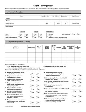
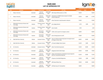
Component IdentificationComponent Identification695 / 795 / 1095 / 1595 / Mark IV / Mark V / Mark VII / Mark XStandard Models:AMBLCOFFONDti14839cGHJKEF8APressure Gauge (not available on all units)GFilterBAmp Switch (not available on all units)HStrainerCON/OFF SwitchJPumpDPressure ControlKDrain TubeEPrime / Spray ValveLModel/Serial TagFTrigger LockMProGuard Status Light332916F
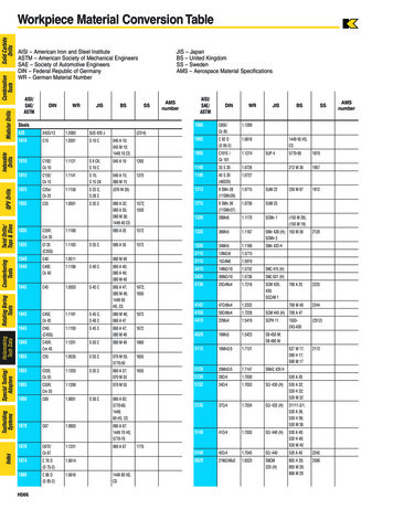
Component Identification695 / 795 / 1095 / 1595 Mark IV / Mark V / Mark VII / Mark XProContractor Models:ARPBCNOFFONMDLKEGHJFFti18239bASmart Control 3.0 DisplayJPumpBAmp Switch (not available on all units)KProConnect IICON/OFF SwitchLTool BoxDPressure ControlMRod Pull FeatureESpray / Prime / Fast FlushNUnit / Serial TagFTrigger LockPDrain TubeGFilterRQuikReelHStrainer332916F9
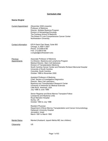
Component Identification1095 / 1595 / Mark V IronMan Models:ANBCOFFMONDLKEGHJFti22935aASmart Control 3.0 DisplayHStrainerBAmp Switch (not available on all units)JPumpCON/OFF SwitchKProConnect IIDPressure ControlLRod Pull FeatureESpray / Prime / Fast FlushMUnit / Serial TagFTrigger LockNDrain TubeGFilter10332916F
GroundingGroundingDo not modify plug! If it will not fit in outlet, havegrounded outlet installed by a qualified electrician. Donot use an adapter.The equipment must be grounded to reduce the riskof static sparking and electric shock. Electric or staticsparking can cause fumes to ignite or explode.Improper grounding can cause electric shock.Grounding provides an escape wire for the electriccurrent.The sprayer cord includes a grounding wire with anappropriate grounding contact. Do not use the sprayer ifthe electrical cord has a damaged ground contact.Power Requirements 100-120V units require 100-120 VAC, 50/60 Hz,15A, 1 phase 230V units require 220-240 VAC, 50/60 Hz,10A-16AExtension CordsUse an extension cord with an undamaged groundcontact.The plug must be plugged into an outlet that is properlyinstalled and grounded in accordance with all localcodes and ordinances.If an extension cord is necessary, use a 3-wire, 12 AWG(2.5 mm2) minimum. Longer cords and higher gaugecords reduce sprayer performance.ti7529bti7528b332916F11
10/16 Amp Switch10/16 Amp SwitchPails(Mark VII and Mark X units)Solvent and oil/based fluids: follow local code. Useonly conductive metal pails, placed on a grounded surface such as concrete.Do not place pail on a nonconductive surface such aspaper or cardboard which interrupts groundingcontinuity.ti22874aSelect 10A or 16A setting based on your circuit rating.ti5850bGrounding a metal pail: connect a ground wire to thepail by clamping one end to pail and other end to a trueearth ground.ti14840a15/20 Amp Switch(120V 1595 and Mark V units)ti22936aSelect 15A or 20A setting based on your circuit rating.To maintain grounding continuity when flushing orrelieving pressure: hold metal part of spray gun firmlyto side of a grounded metal pail. Then trigger gun.ti18247b12332916F
Pressure Relief ProcedurePressure Relief ProcedureFollow the Pressure Relief Procedure wheneveryou see this symbol.This equipment stays pressurized until pressure ismanually relieved. To help prevent serious injuryfrom pressurized fluid, such as skin injection,splashing fluid and moving parts, follow the PressureRelief Procedure when you stop spraying and beforecleaning, checking, or servicing the equipment.1. Turn power OFF. Wait 7 seconds for power todissipate.4. Turn pressure to lowest setting. Trigger gun torelieve pressure.ti22937a5. Put drain tube in pail. Turn prime valve down toDRAIN position. Leave prime valve in DRAIN position until you are ready to spray again.2. Engage trigger lock.ti14842ati18199ati2595a6. If you suspect the spray tip or hose is clogged orthat pressure has not been fully relieved after following the steps above, VERY SLOWLY loosen tipguard retaining nut or hose end coupling to relievepressure gradually, then loosen completely. Clearhose or tip obstruction.3. Remove guard and SwitchTip.ti2769a332916F13
SetupSetup5. Check inlet strainer for clogs and debris.1. All sprayers except ProContractor: ConnectGraco airless hose to sprayer. Tighten securely.ti17608b6. Fill throat packing nut with Graco TSL to preventpremature packing wear. Do this each time youspray.ti22875aIf using the optional hopper, remove the nipple fittingfrom the filter. Install 45 elbow (from parts box) intofilter and install nipple fitting into elbow. Then connect the hose to the nipple.ti18421b7. Turn power OFF.ti18631aNOTE: Make sure nipple fitting is angled away fromhopper so the hose can be easily installed.2. Connect whip hose (if applicable) and gun to otherend of hose. Tighten securely.ti18195a3. Engage trigger lock.ti18199a4. Remove tip guard.ti22950a8. Plug power supply cord into a properly groundedelectrical outlet.9. Turn prime valve down to DRAIN position.ti14842a10. Place pump in grounded metal pail partially filledwith flushing fluid. Attach ground wire to pail andto true earth ground. Perform steps 1 - 5 of Startupto flush out storage oil shipped in sprayer. Usewater to flush water-base paint and mineral spirits toflush oil-base paint and storage oil.ti2769ati18245b14332916F
StartupStartup6. Hold gun against grounded metal flushing pail. Trigger gun and increase fluid pressure 1/2 turn. Flush1 minute.1. Perform Pressure Relief Procedure, page 13.2. Turn pressure control to lowest pressure.ti22949ati13670b3. Turn power ON.High-pressure spray is able to inject toxins into thebody and cause serious bodily injury. Do not stopleaks with hand or rag.7. Inspect for leaks. If leaks occur, perform PressureRelief Procedure, page 13. Tighten fittings. Perform Startup, steps 1 - 5. If no leaks, proceed tostep 7.8. Place pump in paint pail.ti4266b4. Increase pressure 1/2 turn to start motor and allowfluid to circulate through drain tube for 15 seconds;turn pressure down.ti18244b15sec.9. Trigger gun again into flushing pail until paintappears. Move gun to paint pail and trigger for 20seconds.1/25. Turn prime valve forward to SPRAY position. Disengage trigger lock.ti18248ati14845ati18198a10. Engage trigger lock. Assemble tip and guard, seeinstructions on next page.ti18199a332916F15
Switch Tip InstallationSwitch Tip InstallationSpray1. Spray test pattern. Increase pressure to eliminateheavy edges. Use smaller tip size if pressure adjustment can not eliminate heavy edges.1. Perform Pressure Relief Procedure, page 13.2. Use spray tip (A) to insert OneSeal (B) intoguard (C).CBAti18243ati13023a2. Hold gun perpendicular, 10-12 in. (25-30 cm) fromsurface. Spray back and forth. Overlap by 50%.Trigger gun after moving and release before stopping.3. Insert Switch Tip.ti13024a4. Screw assembly onto gun. Tighten.ti2710ati18242aClearing Tip ClogSKIN INJECTION HAZARDNever point gun at your hand or into a rag!1. Release trigger, engage trigger lock. RotateSwitchTip. Disengage trigger lock. Trigger gun toclear clog.ti13033a2. Engage trigger lock. Return SwitchTip to originalposition. Disengage trigger lock and continue spraying.ti13034a16332916F
Fast Flush (ProContractor and IronMan models only)Fast FlushWatchDog Protection System(ProContractor and IronMan models only)(ProContractor and IronMan models only)To flush the hose and gun at an accelerated speed, perform the following steps:Pump stops automatically when material pail is empty.1. Perform steps 1 - 3 of Cleanup, page 22.1. Perform Startup.To Activate:2. Squeeze gun trigger and turn prime valve down toDRAIN position and then over to FAST FLUSH.ti22938ati22940a2. Turn WatchDog switch ON and WD ON displays.EMPTY displays/flashes and pump stops whenWatchdog protection system detects an emptymaterial pail.3. Continue flushing system until fluid appears clear.ti22033a3. Turn WatchDog switch OFF. Add material or reprimesprayer. Turn pump switch OFF and ON to resetWatchDog protection system. Turn WatchDogswitch back ON to continue to monitor materiallevel.ti22939a332916F17
ProGuardProGuardThis sprayer protects itself against high and low voltage.If the sprayer is plugged into a power source that is toolow or too high the sprayer will stop operating.One of three error codes will be displayed:ErrorCodeStandard ModelsStandard models come equipped with a ProGuard status indicator light. This light has three different states ofoperation: ON, blink, and OFF.ErrorCodeProContractor and IronMan ModelsDefinitionLight is ONUnit is powered and operating normally.Light is BlinkingVoltage supply is too low or too high forsprayer and will not run until it is pluggedinto a good power supply.Light is OFFNo power to sprayer, or there is anothererror other than the voltage supply.See Troubleshooting (page 24) to determine the causeof any errors.DefinitionMultiple incoming voltage surgesdetected - unplug sprayer andlocate good voltage supply toprevent damage to electronics.Typical cause of this error is plugginginto a circuit that is higher than therated voltage of the sprayer. Find acircuit that supplies the correctvoltage.Incoming voltage too low forsprayer operation - unplug sprayerand locate good voltage supply toprevent damage to electronics.Typical cause of this error is otherequipment on the same circuit orgenerator frequently turning on/offunder load. Find a circuit that isdedicated to the sprayer.Sprayer plugged into wrongvoltage - unplug sprayer andlocate correct voltage supply.Typical cause of this error is a GFCIbox that is wired for the wrongvoltage (240V vs. 120V). No damagehas occurred to the sprayer. Find acircuit with the correct voltage and thesprayer will run correctly.ProGuardStatus Indicator Light18332916F
Hose ReelHose Reel(ProContractor models only)3. Pull reel handle up and turn clockwise to reel inhose.Moving parts can pinch, cut or amputate fingers andother body parts. To avoid injury from moving parts, besure to keep your head clear of hose reel while windingup hose.1. Make sure hose is routed through hose guide.ti13502bti13503bNOTE: The hose reel can be locked into two positions:Usage (A) and Storage (B).(A)(B)ti18241a2. Lift and turn pivot lock 90 to unlock hose reel. Pullon hose to remove it from hose reel.ti13563bti13501c332916F19
Digital Tracking System (ProContractor and IronMan models only)Digital Tracking System(ProContractor and IronMan models only)Job Gallons1. Short press DTS button to move to Job Gallons (orliters x 10).Operation Main MenuShort press to move to next display. Press and hold (5seconds) to change units or reset data.ti22717ati22719a1. Turn pressure to lowest setting. Trigger gun torelieve pressure. Turn prime valve down to DRAINposition.NOTE: JOB scrolls past, then the number of gallonssprayed above 400 psi (28 bar, 2.8 MPa) for MarkVII and Mark X displays; 1000 psi (70 bar, 7 MPa)for all other models.2. Press and hold to reset to zero.Lifetime Gallons1. Short press DTS button to move to Lifetime Gallons(or liters x 10).ti22941a2. Turn power ON. Pressure display appears. Dasheswill not appear unless pressure is less than 200 psi(14 bar, 1,4 MPa).ti22942aNOTE: LIFE scrolls briefly, then the number of gallons sprayed above 400 psi (28 bar, 2.8 MPa) forMark VII and Mark X displays; 1000 psi (70 bar, 7MPa) for all other models.ti22718aChange Display UnitsPress and hold DTS button for 5 seconds to changepressure units (psi, bar, MPa) to desired units. Selection of bar or MPa changes gallons to liters x 10. Tochange display units DTS must be in pressure displaymode and pressure must be at zero.ti22876a20332916F
Digital Tracking System (ProContractor and IronMan models only)Secondary Menu - Stored Data1.Perform Pressure Relief, steps 1 - 4 if they have notalready been done.2.Turn power switch on while holding DTS button down.7.Short press DTS button. LAST CODE scrolls by and lastcode is displayed; e.g. E 07 (see Repair manual).ti22722a8.Press and hold DTS button to clear code to zero.ti22881a3.SERIAL NUMBER scrolls past and then serial number(e.g. 00001) displays.ti22723a9.ti22720aShort press DTS button and SPRAYER PART # scrollspast and the PART # is displayed.Short press DTS button and DATE CODE scrolls past andDATE CODE is displayed.6.Short press DTS button and MOTOR HOURS scrolls pastand then total motor run hours are displayed.ti35549a5.10. Press and hold DTS button adjust WatchDog sensitivity.Selections are HIGH, MED, or LOW. HIGH is a betterchoice when spraying paints and LOW is a better whenspraying texture. Release DTS button whenti22725bti35548ati22724b4.Short press DTS button. W-DOG scrolls past then OFFdisplays if watchdog switch is OFF. ON displays if Watchdog switch is ON.ti22721a332916F11. Short press to move to SOFTWARE REV. Short pressDTS button. MOTOR ID RESISTOR scrolls by and modelcode number (see below).Motor ID NumberModels024610695795 / Mark IV1095 / 230V Mark V1595 / 120V Mark V / MARK VIIMark X21
CleanupCleanup5. Turn prime valve down to DRAIN position and allowflushing fluid to circulate until flushing fluid appearsclear.1. Perform Pressure Relief Procedure (page 13),steps 1 - 4. Remove tip guard from gun.NOTE: Use water for water-base material, mineralspirits for oil-base material, or other solvents recommended by manufacturer.2. Turn power ON. Turn prime valve forward to SPRAYposition.ti22945a6. Turn prime valve forward to SPRAY position. Triggergun into flushing pail to purge fluid from hose.ti22946ati22943a3. Increase pressure to 1/2. Hold gun against pail. Disengage trigger lock. Trigger gun until flushing fluidappears.ti18248a7. Raise pump above flushing fluid and run sprayer for15 to 30 seconds to drain fluid. Turn power OFF.ti22944ati18249a4. Move gun to waste pail, hold gun against pail, trigger gun to thoroughly flush system. Release triggerand engage trigger lock.ti22947a8. Turn prime valve down DRAIN position. Unplugsprayer.ti18248a22ti22945a332916F
Cleanup9. Remove filters from gun and sprayer, if installed.Clean and inspect. Install filters.11. Wipe sprayer, hose and gun with a rag soaked inwater or mineral spirits.ti2776ati15018ati13454a10. If flushing with water, flush again with mineral spirits,or Pump Armor, to leave a protective coating to prevent freezing or corrosion.ti2895aPump Armor332916F23
TroubleshootingTroubleshootingMechanical/Fluid FlowPerform Pressure Relief Procedure; page 13.TYPE OF PROBLEMFor units with display:CODE XX is displayed.WHAT TO CHECKIf check is OK, go to next checkWHAT TO DOWhen check is not OK, refer to this columnFault condition existsDetermine fault correction from table,page 27.Spray tip wornFollow Pressure Relief Procedure on page13, then replace tip. See your separate gun ortip manual.Spray tip cloggedRelieve pressure. Check and clean spray tip.Paint supplyRefill and reprime pump.Intake strainer cloggedRemove and clean, then reinstallIntake valve ball and piston ball arenot seating properlyRemove intake valve and clean. Check ballsand seats for nicks; replace if necessary; seepump manual. Strain paint before using toremove particles that could clog pump.Fluid filter, tip filter, or tip is cloggedor dirty.Clean filter; see operation manual.Prime valve leakingRelieve pressure. Repair prime valve.Verify pump does not continue tostroke when gun trigger is released.(Prime valve not leaking.)Service pump; see pump manual.For units with no display:ProGuard status light isblinking or the light is offand there is power to thesprayer.Pump output is lowLeaking around throat packing nutReplace packings; see pump manual. Alsowhich may indicate worn or damaged check piston valve seat for hardened paint orpackings.nicks and replace if necessary. Tighten packingnut/wet-cup.24332916F
TroubleshootingTYPE OF PROBLEMPump output is lowWHAT TO CHECKIf check is OK, go to next checkWHAT TO DOWhen check is not OK, refe
695 / 795 / 1095 / 1595 / Mark IV / Mark V / Mark VII / Mark X Electric Airless Sprayers For Portable Airless Spraying of Architectural Coatings and Paints. For professional use only. Not approved for use in European explosive atmosphere locations. 3300 psi (227 bar, 22.7 MPa) Maximum Working Pressure Important Safety Instructions