Transcription
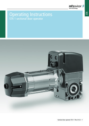
ENOperating InstructionsSTA 1 sectional door operatorSectional door operator STA 1 / Rev. D 0.3 – 1
1. Contents2. Information in this document1.2.3.4.5.Original operating instructions Copyright. No part of these instructions may be reproduced withoutour prior approval. Subject to alterations in the interest of technical progress. All dimensions given in mm. The diagrams in this manual are not to scale.6.7.8.9.10.Contents 2Information in this document 2General safety instructions 3Overview of products 4Installation 55.1Preparation . . . . . . . . . . . . . . . . . . . . . . . . . 55.2Push-on assembly . . . . . . . . . . . . . . . . . . . . 55.3Installation of the emergency hand chain(only for operators with emergency handchain) . . . . . . . . . . . . . . . . . . . . . . . . . . . . . 6Initial Operation 76.1Preparation . . . . . . . . . . . . . . . . . . . . . . . . . 76.2Connection . . . . . . . . . . . . . . . . . . . . . . . . . 76.3Manual settings . . . . . . . . . . . . . . . . . . . . . . 96.4Digital settings –Limit switch and safety circuit for drive . . . . 106.5Check the system . . . . . . . . . . . . . . . . . . . . 11Emergency operation 12Maintenance 13Technical data 14Manufacturer‘s Declaration 22Key to symbolsDANGER!Indicates a hazard with a high level of risk which, if notavoided, will result in death or serious injury.WARNING!Indicates a hazard with a medium level of risk which, if notavoided, could result in death or serious injury.CAUTION!Indicates a hazard with a low level of risk which, if notavoided, could result in minor or moderate injury.ATTENTION!Indicates an imminent danger of damage or destruction.CHECKIndicates a check to be performed.REFERENCEReference to separate documents which must be compliedwith. Action request List, itemisation Reference to other sections of this document2 – Sectional door operator STA 1 / Rev. D 0.3
EN3. General safety instructionsDANGER!Failure to observe the instructions in this document can result in mortal danger! Observe all safety information contained in this document.WarrantyThe function and safety of the equipment is only guaranteedif the warning and safety instructions included in these operating instructions are adhered to.MFZ Antriebe GmbH & Co. KG is not liable for personalinjury or damage to property if these occur as a result of the warnings and safety advice being disregarded.MFZ does not accept any liability or warranty for damage dueto the use of non-approved spare parts and accessories.Instructions regarding installation, connection andmaintenance The controls must be disconnected from the electricity supply before carrying out electrical works. It must beensured that the electricity supply remains disconnectedduring the works. Local protective regulations must be complied with. Mains cables and control cables must be laid separately.Observe the valid standards and regulations!Intended useThe operators of the STA 1 range are designed exclusively foropening and closing weight counterbalanced sectional doors.Target groupOnly qualified and trained specialists are permitted to installand service the operator. Qualified and trained professionalsfulfil the following requirements: knowledge of the general and specific safety and accidentprevention regulations, knowledge of the relevant regulations, trained in the use and care of appropriate safety equipment, Capable of recognising the dangers associated with installation.Only qualified and trained electricians may connect the operator and carry out electrical maintenance.Qualified and trained electricians fulfil the following requirements: knowledge of the general and specific safety and accidentprevention regulations, knowledge of the relevant electrical regulations, trained in the use and care of appropriate safety equipment, capable of recognising the dangers associated with electricity.Sectional door operator STA 1 / Rev. D 0.3 – 3
4. Overview of productsThe following package options are available for the STA 1operator: STA/STAW 1 E (external control unit with release mechanism) STA/STAW 1 KE (external control unit with chain) STA/STAW 1 KU (external control unit with emergency handcrank) S TA/STAW 1 E - HD (external control unit with releasemechanism, HD*) STA/STAW 1 KE - HD (external control unit with chain, HD*) STA/STAW 1 KU - HD (external control unit with emergencyhand crank, HD*) STAC/STAWC 1 E (integrated control unit with releasemechanism) STAC/STAWC 1 KE (integrated control unit with chain) STAC/STAWC 1 KU (integrated control unit with emergencyhand crank)* HD Operators with this suffix have a higher duty cycle.The precise values for all operators can be found in „9. Technical data“Additional product combinations are possible.Information about these combinations can be obtained fromthe manufacturer.4 – Sectional door operator STA 1 / Rev. D 0.3
EN5. Installation5.1PreparationWARNING!Incorrect installation of the drive can result inserious injury! The drive must be installed free of any tension. The drive must not move on the shaft. The design and subsurface of all components must besuitable for the forces encountered. Installation must only be carried out from a safe standing position (e. g. scaffolding).ATTENTION!Incorrect installation of the drive can result in damage to property!To avoid damage to the drive and the door, the drive mustonly be fitted if the drive is undamaged, the ambient temperature is -20 ºC to 60 ºC., the altitude of the location does not exceed 1,000 m, a suitable protection type has been selected.5.2Push-on assemblyATTENTION!Damage due to improper installation of the drive!To avoid damage to the drive and to the door, the drivemust be mounted on a console or a torque support bracketso that it is vibration damped.REFERENCEThe relevant instructions for the door must be observedwhen fitting the drive to the door.Solid shaft5.2 / 1 Before installation, ensure that– the drive is not blocked,– the drive has been newly prepared after a lengthy storageperiod,– all connections have been carried out correctly– the direction of rotation of the drive motor is correct,– all motor protective devices are active– no other sources of danger exist,– the installation site has been cordoned off over a widearea.Check whether the feather key is suitable for the spring shafton site.Sectional door operator STA 1 / Rev. D 0.3 – 5
Installation5.3Mounting with torque support bracket5.2 / 2BInstallation of the emergency hand chain(only for operators with emergency handchain)To ensure that they work correctly, the chain links must notbe twisted.AC5.3 / 1DFit the torque support bracket/console (A). Grease the spring shaft (B) around the operator seating. Insert the feather key (C) into the spring shaft (B). Place the operator (D) on the spring shaft (B). Secure the feather key (C) against any movement.The feather key can be secured with two hose clamps oradjusting rings. Fix the operator to the torque support bracket with 4 screws.6 – Sectional door operator STA 1 / Rev. D 0.3 Join the ends of the emergency hand chain together withthe chain connecting link.ATTENTION!Incorrect operation of the drive can result in damage to property!To avoid damage to the drive and the door, the emergencyhand chain must be secured while the door is operatedelectrically.
EN6. Initial Operation6.1PreparationDANGER!Danger of fatal electric shock! Before commencing cabling works, you MUST disconnectthe drive system from the mains supply. Ensure that theelectricity supply remains disconnected throughout thecabling works.6.2ConnectionOpen the operator6.2 / 1ATTENTION!Damage due to improper installation of the drive!To avoid damage to the drive, the following points must beobserved: The types of cable and their diameters must be selectedaccording to current regulations. The nominal currents and the type of connection mustcorrespond to those on the motor type plate. The drive details must agree with the connected loads.REFERENCEWhen operated with electronic control units, the corresponding start-up instructions and circuit diagramsmust be complied with. Remove the cover from the operator.Insert the cables6.2 / 2 Feed the cables through the screw fitting into the operator.Sectional door operator STA 1 / Rev. D 0.3 – 7
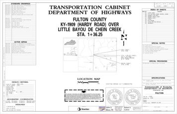
Initial OperationLimit switch connections (plug-in, standard)6.2 / 3S1 Additional limit switch, OPEN (standard only foroperators without integrated control unit)S2Limit switch, OPENS3Safety limit switch, OPENS4Safety limit switch, CLOSEDS5Limit switch, CLOSEDS6 Additional limit switch, CLOSED (standard only foroperators without integrated control unit)S7Safety limit switch for emergency manual operationF2Thermal overload protection for motorLimit switch connections6.2 / 516.2 / 4A42B6.2 / 6CDEFABCDEFPotential-free connection OPENPotential-free connection CLOSESwitch off safety circuitSwitch off OPEN end positionSwitch off CLOSED end positionInternal safety circuit8 – Sectional door operator STA 1 / Rev. D 0.3S1 OPEN additional limitswitch (standard only inthe case of operatorswithout integrated controlunit)S2 Limit switch, OPENS3 Safety limit switch, OPENS4 Safety limit switch, CLOSES5 Limit switch CLOSEDS6 CLOSED additional limitswitch (standard onlyin the case of operatorswithout integrated controlunit)
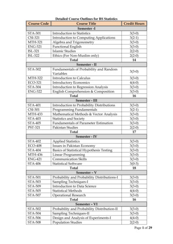
EN3 x 400 V star connection (standard)The motor is factory-wired for connection to a 3 x 400 Vmains supply in star connection.6.3Manual settings6.3 / 1GGHHIIJJKKLL6.2 / 7 Connect all the cables required.Identification of wnGreen3 x 230 V delta connectionTo connect the operator to a 3 x 230 V mains supply, pleaseconsult the manufacturer.1 x 230V connectionThe motor is factory-wired for connection to a 230V/1-phasemains supply.6.2 / 8OPEN additional limit switch - S1(potential-free change-over contact)BLimit switch, OPEN - S2CSafety limit switch, OPEN - S3DSafety limit switch, CLOSED - S4ELimit switch, CLOSED - S5FAdditional limit switch, CLOSED - S6(potential-free change-over contact)GControl cam for additional limit switch, OPEN (green)HControl cam for limit switch, OPEN (green)IControl cam for safety limit switch, OPEN (red)JControl cam for safety limit switch, CLOSED (red)KControl cam for limit switch, CLOSED (white)L Control cam for additional limit switch, CLOSED(white)AUFZUPEN Connect all the cables required.Identification of wiresAUF (OPEN) blueZU (CLOSE)blueN redSectional door operator STA 1 / Rev. D 0.3 – 9
Initial OperationSet the OPEN end position Drive the door to the OPEN end position. Set the control cam (H) so that the OPEN limit switch (B) isactuated. Tighten the locking screw (N).6.3 / 2The OPEN safety limit switch (C) must be set in such a waythat it switches immediately when the OPEN limit switch (B)is passed over.MN Adjust the OPEN safety limit switch (C).6.4MNFine adjustment screwLocking screwDigital settings –Limit switch and safety circuit for driveElectronic interface6.4 / 1Each control cam has a locking screw (N) and a fine adjustment screw (M).AThe locking screw (N) is used to lock the correspondingcontrol cam in the desired position. Finer adjustment can bemade with the fine adjustment screw (M).Set the CLOSED end position Drive the door to the CLOSED end position. Set the control cam (K) so that the CLOSED limit switch (E)is actuated. Tighten the locking screw (N).The CLOSED safety limit switch (D) must be set in such a waythat it switches immediately when the CLOSED limit switch (E)is passed over. Adjust the CLOSED safety limit switch (D).10 – Sectional door operator STA 1 / Rev. D 0.3BA:AVE plug (absolute value encoder plug)B: AVE plug terminal (absolute value encoder plug terminal)REFERENCEPlease refer to the control unit operating manual for instructions on setting the end positions.
ENWiring allocation, AVE (absolute value encoder) plug6.4 / 26.5Check the systemCheck the direction of travel Drive the door in the CLOSED direction.The operator must close the door. Drive the door in the OPEN direction.The drive must open the door.The numbers on the plug are also the wire-numbers.4:Safety circuit input5:RS 485 B6:GND7:RS485 A8:Safety circuit output9:7.18V DCIf the direction of movement of the door does not match thebutton commands, change the direction of rotation.The direction of movement must then be checked again.AVE (absolute value encoder) plug terminal (7-12)Check the limit switch settings Drive the door to the CLOSED end position.The drive must stop in the desired position.6.4 / 3REFERENCEPlease refer to the control unit operating manual for instructions on changing the direction of rotation. Drive the door to the OPEN end position.The operator must stop in the desired position. Check the seat of the fixing screws.Check the mechanical functionsAfter assembling and installing all components the functionsof the system must be checked. Check all the functions of the system. Check that the operator runs smoothly. Check whether the operator is leaking oil.C:Thermal element in the driveD: Manual emergency control(emergency crank or emergency chain)If the operator makes unusual noises or leaks oil: The operator must be taken out of service immediately, The customer service must be informed.Sectional door operator STA 1 / Rev. D 0.3 – 11
7. Emergency operationWARNING!Improper use may result in serious injury!To avoid injury, the following points must be observed: Emergency operation must only be carried out from asafe standing position. Emergency operation must only be carried out when themotor is stationary. The system must be disconnected from the power supplyduring emergency operation.Operation with emergency hand chain7/1During maintenance works or in the case of an electrical fault,the door can be moved towards the OPEN or CLOSED positions with the help of the emergency operation equipment.If the door is moved beyond the CLOSED or OPENend positions, the drive can no longer be activatedelectrically. Release the emergency hand chain from its fixing. Move the door in the OPEN or CLOSE direction by pulling onthe emergency hand chain on the side concerned.Operation with emergency hand crank7/2 Push the emergency hand crank into the operator as far asit will go. Move the door in the OPEN or CLOSE direction by turningthe emergency hand crank. Remove the emergency hand crank from the operator aftercompleting emergency manual operation.12 – Sectional door operator STA 1 / Rev. D 0.3
Operation with release mechanismWARNING!Risk of serious injury due to uncontrolled movement of the door!To avoid injury, drive units with a release mechanismrequire that a fall protection is mounted on the door.Without a fall protection, the door does not comply withdirective ASR A1.7.7/3DANGER!Danger of fatal electric shock! Before commencing cabling works, you MUST disconnectthe drive system from the mains supply. Ensure that theelectricity supply remains disconnected throughout thecabling works.ATTENTION!Improper maintenance of the drive can result inproperty damage!To avoid damage to the drive and door, the following pointsmust be observed: Maintenance must only be carried out by authorizedpersons. Directive ASR A1.7 must be complied with. Worn or faulty parts must be replaced. Only approved parts must be installed. All maintenance work must be documented.The drive unit has lifetime lubrication and is maintenancefree.The hollow shaft must be kept rust-free. Pull on the red loop.The gate can be moved manually. Pull on the green loop.The door can be moved with the operator. Check that all mountings have been securely tightened. Check the spring tension on the door.The springs must be adjusted so that they are weight counterbalanced. Check the brake (if available). Check the limit switches and safety switches. Check for noises and oil leaks. Check the mounting of the drive for corrosion. Check the housing for damage.Faulty parts that have been replaced must be disposed ofproperly in accordance with the regulations.Sectional door operator STA 1 / Rev. D 0.3 – 13EN8. Maintenance
9. Technical dataSTA 1-11-19STAC 1-11-19STA 1-10-24STAC 1-10-24STA 1-13-15STAC 1-13-15STA 1-12-19STAC 1-12-19STA 1-11-24STAC 1-11-24STA 1-10-30STAC 1-10-30Driving torque (Nm):110100130120110100Static holding torque (Nm):600600600600600600Driving motor speed (min -1):1924151924300.370.370.550.550.550.55230 / 400 / 3 230 / 400 / 3 230 / 400 / 3 230 / 400 / 3 230 / 400 / 3 230 / 400 / 3 Mains frequency Hz:505050505050Control voltage: (V):242424242424Nominal motor current (A):3.5 / 2.03.5 / 2.03.1 / 1.84.1 / 2.44.1 / 2.43.5 / 2.0Maximum no. of operatingcycles per hour *:202020202020Fuse protection on site (A):10,010,010,010,010,010,0545454545454-20 / 60-20 / 60-20 / 60-20 / 60-20 / 60-20 / 60 70 70 70 70 70 70Weight per piece (kg):151515151515Maximum number of revolutions of driven shaft:20202020202025.425.425.425.425.425.4Type (E / KU / KE):Motor output (kw):Operating voltage (V):Protection type (IP)Temperature range ( C)**:Continuous sound pressure level(dB (A)):Hollow shaft (mm):* 1 cycle 1 complete door movement (open and then close the door).The values given assume an even distribution.**Temperature ranges -5 C: Type of oil and electric heater on request.14 – Sectional door operator STA 1 / Rev. D 0.3
ENType (E / KU / KE):STA 1-13-15HDSTA 1-12-19HDSTA 1-11-24HDSTA 1-10-30HDSTAW 1-7-19STAWC 1-7-19Driving torque (Nm):13012011010070Static holding torque (Nm):600600600600600Driving motor speed (min -1):15192430190.550.550.550.550.37230 / 400 / 3 230 / 400 / 3 230 / 400 / 3 230 / 400 / 3 230 / 1 Mains frequency Hz:5050505050Control voltage: (V):2424242424Nominal motor current (A):3.1 / 1.83.0 / 1.73.0 / 1.73.0 / 1.76.2Maximum no. of operatingcycles per hour *:303030308Fuse protection on site (A):10,010,010,010,010,05454545454-20 / 60-20 / 60-20 / 60-20 / 60-20 / 60 70 70 70 70-Weight per piece (kg):2323232323Maximum number of revolutions of driven shaft:202020202025.425.425.425.425.4Motor output (kw):Operating voltage (V):Protection type (IP)Temperature range ( C)**:Continuous sound pressure level(dB (A)):Hollow shaft (mm):* 1 cycle 1 complete door movement (open and then close the door).The values given assume an even distribution.**Temperature ranges -5 C: Type of oil and electric heater on request.Sectional door operator STA 1 / Rev. D 0.3 – 15
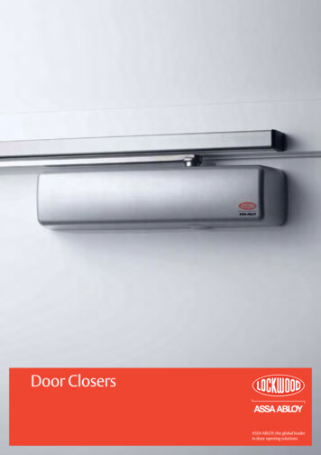
Technical dataSTA/STAW 1 6504x M8x16 deep, on both sidesSTA/STAW 1 KE4091021401052459/2551201046.353.5.425A4x M8x16 deep, on both sides16 – Sectional door operator STA 1 / Rev. D 0.3A5510814516690
ENSTA/STAW 1 145A4x M8x16 deep, on both sidesSTA/STAW 1 E - 554x M8x16 deep, on both sidesSectional door operator STA 1 / Rev. D 0.3 – 17
Technical dataSTA/STAW 1 KE - 14525.4A4x M8x16 deep, on both sidesSTA/STAW 1 KU - HD9/6396.41043.525A4x M8x16 deep, on both sides18 – Sectional door operator STA 1 / Rev. D 0.3120556.3510514024513655108145A18063
ENSTAC/STAWC 1 A554x M8x16 deep, on both sidesSTAC/STAWC 1 .35A4x M8x16 deep, on both sidesSectional door operator STA 1 / Rev. D 0.3 – 19
Technical dataSTAC/STAWC 1 KU102399120551401052459/9A104556.353.5425.A4x M8x16 deep, on both sides20 – Sectional door operator STA 1 / Rev. D 0.310814516680
ENSectional door operator STA 1 / Rev. D 0.3 – 21
10. Manufacturer‘s DeclarationDeclaration of incorporationwithin the context of Machinery Directive 2006/42/EC for incorporation in anincomplete machine according to Appendix II, Part 1BMFZ Antriebe GmbH & Co.KGNeue Mühle 4D - 48739 LegdenDeclaration of conformitywithin the context of the directives on Electromagnetic Compatibility 2014/30/EU and RoHS 2011/65/EUWe hereby declare that the following listed productProduct designation:Type designation:Sectional door operatorSTA1as an incomplete machine specified exclusively for integration with a door system and designed, constructed, and produced inconjunction with the following directives:Machinery Directive 2006/42/ECElectromagnetic Compatibility Directive 2014/30/EURoHS Directive 2011/65/EUFurthermore, the requirements of the Low-Voltage Directive 2014/35/EU are met according to Appendix I Part 1.5.1of the Machinery Directive 2006/42/EC.Applied and consulted standards:EN 12453Doors - Safety in use of power operated doors: Requirements and test methodsEN 12604Doors - Mechanical aspects: Requirements and test methodsEN 60335-1Household and similar electrical appliances - Safety - Part 1: General requirementsEN 60335-2-103 Household and similar electrical appliances - Safety - Part 2-103: Particular requirements for drives for gates, doors and windowsEN 61000-6-2 Electromagnetic compatibility (EMC) - Part 6-2: Generic standards - Immunity standard for industrial environmentsEN 61000-6-3 Electromagnetic compatibility (EMC) - Part 6-3: Generic standards - Emission standard for residential, commercial andlight-industrial environmentsThe special technical documents were created according to Appendix VII Part B of the Machinery Directive (2006/42/EC).We are obligated to transmit these to market monitoring agencies in a timely manner upon justified request in electronic form.Authorised representative for compiling the technical documents:MFZ Antriebe GmbH & Co. KG - Neue Mühle 4 - 48739 Legden - GermanyIncomplete machines within the context of EC Directive 2006/42/EC are therefore only specified for incorporation with other machinesor with other incomplete machines or systems or combined with them to form a machine within the contact of the directive indicatedabove. For this reason, this product may only be commissioned once it has been determined that the complete machine /system intowhich it has been incorporated corresponds with the indicated EC guidelines.22 – Sectional door operator STA 1 / Rev. D 0.3
ENIn case of changes to the product that are not confirmed by us, this declaration is void.Legden, dated 01.07.2018Dirk Wesseling, General ManagerSectional door operator STA 1 / Rev. D 0.3 – 23
#1700007835#97609
S7 Safety limit switch for emergency manual operation F2 Thermal overload protection for motor Limit switch connections 6.2 / 5 1 4 2 6.2 / 6 S1 OPEN additional limit switch (standard only in the case of operators without integrated control unit) S2 Limit switch, OPEN S3 Safety limit switch, OPEN S4 Safety limit switch, CLOSE