Transcription
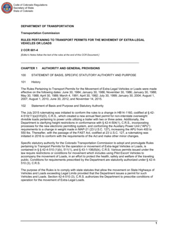
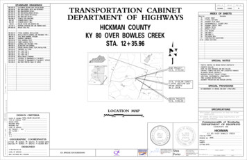
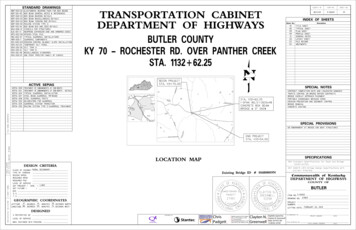
STANDARD DRAWINGSBDP-001-05Box Beam General Notes and ReferencesBDP-002-03Box Beam Bearing DetailsBDP-003-03Box Beam Miscellaneous DetailsBDP-004-03Box Beam Tension Rod DetailsBDP-005-05Railing System Type IIBDP-008-04Box Beam B21 and CB21 DetailsBGX-006-10Stencils for StructuresBJE-001-13Neoprene Expansion Dams and Armored EdgesRBR-005-11Guardrail ComponentsRDI-040-01Erosion Control Blanket Slope InstallationRDX-210-03Temporary Silt FenceRDX-220-05Silt Trap Type ARDX-225-01Silt Trap Type BRDX-230-01Silt Trap Type CRGX-001-06Miscellaneous StandardsRGX-200-01One Point Proctor Family of CurvesSEPIA 009Treatment of Embankments at End BentsSEPIA 010Treatment of Embankments at End Bents-DetailsSEPIA 024Typical Guardrail InstallationsSEPIA 027Steel beam Guardrail "W" BeamSEPIA 028Steel Guardrail PostsSEPIA 032Delineators for GuardrailSEPIA 033Guardrail System TransitionSEPIA 035Railing System Type II Guardrail TreatmentCOUNTY OFFULTONTRANSPORTATION CABINETDEPARTMENT OF HIGHWAYSITEM NO.SHEET NO.1-10009R1INDEX OF SHEETSSheet No.FULTON COUNTYKY-1909 (HARDY ROAD) OVERLITTLE BAYOU DE CHEIN CREEKSTA. 1 36.25DescriptionR1LAYOUT SHEETR2TYP. SECTIONS, COORD. CONTROL, LEGENDR3ROADWAY PLAN SHEETR4ROADWAY PROFILE SHEETS1GENERAL NOTESS2LAYOUTS3PILE RECORDS416" DIA PIPE PILE DETAILSS5ABUTMENTSFILE NAME: .\d0143495\038B00075N R1.dgnACTIVE SEPIASSPECIAL NOTESFor Traffic ControlFor Bridge Overlay Approach PavementFor Erosion Prevention and Sediment ControlFor Contract Completion Date and Liquidated DamagesEND CONST.STA 1 95For Portable Chageable Message SignsFor Tree Clearing RestrictionsFor Concrete CoatingSTA. 1 36.25 CONST.52’ x 24’ CB21BOX BEAM BRIDGE@ 0 SKEWSPECIAL PROVISIONS69 Embankment at Bridge End Bent StructuresUSER: jom ossDATE PLOTTED: 1/4/20195:20:47 PMBEGIN CONST.STA. 0 85SPECIFICATIONSLOCATION MAP2012 Standard Specifications for Road and BridgeConstruction.DESIGN CRITERIACLASS OF HIGHWAYTYPE OF TERRAINRURAL LOCAL0’1000’2000’4000’2017 AASHTO LRFD Bridge Design Specifications withCurrent Interims.EXISTING BRIDGE ID # 038B00075NLEVELCommonwealth of KentuckyDEPARTMENT OF HIGHWAYSDESIGN SPEEDD %GEOGRAPHIC COORDINATESLATITUDE36LONGITUDE88 DEGREESDEGREES31MINUTES55 MINUTES43SECONDS NORTH33SECONDS WESTOF KENTUJOHN S.MOSS17060LDICENSESINONAL ESFEPROT %The contractor is instructed to call 1-800-752-6007 to reach KY 811, the one-call systemfor information on the location of existing underground utilities. The call is to be placeda minimum of two (2) and no more than ten (10) business days prior to excavation. Thecontractor should be aware that owners of underground facilities are not required to bemembers of the KY 811 one-call Before-U-Dig (BUD) service. The contractor must coordinateexcavation with the utility owners, including those whom do not subscribe to KY 811. Itmay be necessary for the contractor to contact the County Court Clerk to determine whatutility companies have facilities in the area.STA)DHVETETCOUNTY OFOF KENTUROBERT V.CATRON32481LDICENSEFULTONYCKADT FUTURE (2017YCKE-SHEET NAME:175 )SFEPROMicroStation v8.11.9.832ADT PRESENT (GINE ERBEFORE YOU DIGLEVEL OF SERVICEGINE ERREQUIRED PSDSTAREQUIRED NPSDSINONAL EITEM NO.1-10009DRAWING NO.27858PROJECTNUMBER:LETTING DATE:FEBRUARY 22, 2019DESIGNED% RESTRICTED SDLEVEL OF SERVICEMAX. DISTANCE W/O PASSINGPREPARED BYJohn S.Moss, PEDigitally signed byJohn S. Moss, PEDate: 2019.01.0417:38:16 -05'00'Robert V.CatronRECOMMENDED BY:Digitally signed by Robert V. CatronDN: cn Robert V. Catron, o, ou,email robert.catron@stantec.com,c USDate: 2019.01.04 17:35:35 -05'00'PROJECT MANAGERDATE:PLAN APPROVED BY:STATE HIGHWAY ENGINEERDATE:
CONVENTIONAL SIGNSdayRodr9- Ha09KY 15700B083D # 0eIgdiBrSURVEY LINE400’ V.C.GRADE LINECOUNTY OFITEM NO.SHEET NO.FULTON1-10009.00R2!GROUND LINE1’ (Typ)8’-0"8’-0"2’ (Typ)COUNTY LINECORPORATE LIMITSGrade pointPLEXIST. PROPERTY LINEthEXIST. RIGHT OF WAY & PROPERTY LINEPROPOSED RIGHT OF WAYVARIESVARIESRIGHT OF WAY MONUMENTBENCH MARKB.M. NO.4NORMAL SECTIONKY-1909ESRIVAEXISTING R/W MARKERRIGHT OF WAY MONUMENTEXISTING/PROPOSEDPROJECT COORDINATESCoordinates for horizontal control were obtained by redundant GPS observations using Trimble R10GNSS receivers. On the NAD83 Kentucky State Plane Coordinate System, KY Single Zone, US SurveyFeet utilizing the KYCORS RTN GPS Network on October 19, 2018. Coordinates shown are State PlaneCoordinates, US Survey Feet. No project datum factor was calculated or used for this project.VARIESBASIS OF ELEVATIONSElevations were established by redundant S7 Robot and GPS observations NAVD88 vertical datum, Geoid12B utilizing the KYCORS RTN Network.THNote:UTILITY TEST HOLECOORDINATE CONTROL POINTSBridge Typical Section is shown on Structure drawings.EXISTING ROADState Plane CoordinatesRAILROADFENCE (CONTROLLED ACCESS)POINTSTATIONDESCRIPTIONFENCE (EXCEPT STONE AND HEDGE)NORTH (Y) EAST (X)OFFSETELEV. (Z)TREE LINECP #15/8" REBAR & CAP3368243.715 3988144.168365.393BEYOND CENTERLINECP #25/8" REBAR & CAP3367850.597 3988079.937355.9161 49.28CP #35/8" REBAR & CAP3367273.319 3988082.121355.661BEYOND CENTERLINETREESPIPE CULVERT33.89’ LT.CULVERTBRIDGEBUILDINGS1-SFRAME1-SBRICKEND TREATMENTSHED2-SBRICKCENTERLINE CONTROL POINTSTERMINALSECTIONGUARDRAILGUARDRAILState Plane CoordinatesSTATIONPOINTFILE NAME: .\d0143495\038B00075N R2.dgnEXISTINGOFFSETNORTH (Y) EAST (X)LIGHTING POLEPOWER POLEPOB3367700.063 3988107.7410 000.00POE3368125.923 3988125.0274 26.210.00JOINT POWER & TELEPHONE POLETELEPHONE & TELEGRAPH POLEANCHOR, POWER OR TELEPHONESTUB POWERSTUB TELEPHONEWATER MAINGAS MAINGM6"GMTELECTRIC DUCTEETVTVSTORM SEWER (WITH MANHOLE)10:01:16 AM6"WMTDIRECT BURIAL TV CABLEDATE PLOTTED: 1/4/2019WMTELEPHONE DUCTSANITARY SEWER (WITH MANHOLE)USER: jom ossPROPOSEDSANSANSTORMSTORMDIRECT BURIAL ELECTRIC CABLEEEEDIRECT BURIAL TELEPHONE CABLETTTOVERHEAD WIRETRAFFIC LIGHTSELECTRIC MANHOLEEMHEMHTELEPHONE MANHOLETMHTMHSTONE FENCEHEDGE FENCESWAMP OR MARSHSPRINGSSINKHOLEQUARRY SITEMicroStation v8.11.7.443E-SHEET NAME:BLUE LINE STREAMINTERMITTENT STREAMOR DITCHLAKES OR PONDSREGULATED FLOODWAYNORTH POINTPREPARED BYNTSKY-1909 (HARDY ROAD) OVERLITTLE BAYOU DE CHEIN CREEKTYP. SECTIONS, COORD.CONTROL, LEGEND
FULTON1-10009.00R34 26Sta. 1 58 LT to Sta. 1 64 LT,Remove 12.5 LF of Existing GuardrailLt. Sta. 1 62 to Lt. Sta. 1 69, Construct 12.5 LF of Guardrail W Beam S Face-ALt. Sta. 1 62 Connect to Guardrail System Type II, Lt. Sta. 1 69 ConstructTerminal Section No. 1Wiley R. PinsonPOE 4 26.21Lt. Sta. 1 10, Connect to Guardrail System Type IISHEET NO.4 00Lt. Sta. 0 73, Connect to Existing GuardrailPOB 0 00.00Lt. Sta. 0 73 to Lt. Sta. 1 10, Construct 25 LF of Guardrail W Beam S Face-AITEM NO.3 002 001 000 00Sta. 0 73 LT to Sta. 1 15 LT,Remove 42 LF of Existing GuardrailCOUNTY OFDavid LuskJennifer Lusk (wf)STA. 0 85CPBEGIN CONST.END CONST.#2EX. R/WSTA. 1 95B-1FOMGRAVELEX. R/WKY 1909 - HARDY ROADEX. R/WExistingBridgeFILE NAME: .\d0143495\038B00075N R3.dgn(Remove)Rt. Sta. 0 45 Construct Guardrail End Treatment Type 4ARt. Sta. 1 10, Connect to Guardrail System Type IIRt. Sta. 1 87 to Rt. Sta. 2 00, Construct 12.5 LF of Guardrail W Beam S Face,Rt. Sta. 2 00 Connect to Existing GuardrailGertrude A. AustinSta. 1 58 RT to Sta. 2 00 RT,Remove 42 LF of Existing GuardrailRAIL SYSTEM TYPE II KY-1909 !STA.MicroStation v8.11.7.443TOSTA.(LF)END TREATMENTLT1 10-1 6252CONNECT TO GUARDRAIL W BEAM S FACE (EACH END)RT1 10-1 6252CONNECT TO GUARDRAIL W BEAM S FACE (EACH END)E-SHEET NAME:USER: jom ossDATE PLOTTED: 1/4/20195:31:36 PMRt. Sta. 0 47.5 to Rt. Sta. 1 10, Construct 25 LF of Guardrail W Beam S Face-ARt. Sta. 1 62 Connect to Guardrail System Type II, Rt. Sta. 1 87 Connect to W Beam S FaceSIDESta. 0 54 RT to Sta. 1 15 RT,Remove 61 LF of Existing GuardrailRt. Sta. 1 62 to Rt. Sta. 1 87, Construct 25 LF of Guardrail W Beam S Face-ALITTLE BAYOU DE CHEIN CREEKSally Pulley (wf)EX. R/WGertrude A. AustinEX. R/WCharles PulleyKY 2149 AIRPORTROADEX. R/WNotes:1.All material that was placed or had fallen into the creek shall be removedby the Contractor at the end of the project and the creek shall be restoredto its preconstruction condition.0’20’40’80’PREPARED BYSCALE: 1" 40’PLANKY-1909 (HARDY ROAD) OVERLITTLE BAYOU DE CHEIN CREEK
DATUMSCALE: 1" 40’ HORIZONTAL1" 4’ VERTICALCOUNTY OFITEM NO.SHEET NO.FULTON1-10009.00R4360LT.59’SKEW362VPI 1 95.00ELEV 358.49’VPI 0 90.00ELEV 357.92’362364BRIDGE @ 13364SPAN CONCRETE BOX BEAMSTA. 1 36.56 CONST. A SINGLEDATUM360%550.356356354LOW BEAM ELEV. 355.85352352350350348348346346344344342342The existing single span 42’ x 24’ concrete bridge with concrete deckshall be removed in accordance with the specifications. All materialin the existing bridge shall remain the property of the contractor andshall be disposed of in accordance with the specifications. Theexisting structure consists of three spans, piers and concrete abutments.Lump sum payment in full shall include the complete removal of the slab,beams, piers, abutments, bin walls, and all appurtenances. After thebridge is removed,all embankment shall be constructed to a maximumof 2:1 slope and properly protected in accordance with the plans andspecifications.0 000 200 400 600 801 001 201 401 60358.41358.3358.30358.2358.19358.4358.08358.33 80358.04, 2019END CONST.STA. 1 95BEGIN CONST.STA. 0 85354DATE PLOTTED: JanuaryUSER: jom ossE-SHEET NAME:MicroStation v8.11.7.443358357.98FILE NAME: C:\PW WORKING\D0143495\038B00075N R4.DGN3581 804 004 204 40PREPARED BY2 002 202 402 602 803 003 203 403 60PROFILEKY-1909 (HARDY ROAD) OVERLITTLE BAYOU DE CHEIN CREEK
General NotesSpecifications: References to the specifications are to the current edition of theUtilities: The contractor shall be responsible for locating any and all existing utilitiesKentucky Department of Highways Standard Specifications for Road and Bridgeprior to excavation of material or installation of guardrail or other constructionConstruction including any current supplemental specifications. All references toactivities that may involve utilities (overhead or underground).the AASHTO specifications are to the AASHTO LRFD Bridge Design Specifications,Verifying Field Conditions: The contractor shall field verify all dimensions before ordering8th edition with interims.material. New material that is unsuitable because of variations in the existing structureDesign Load: This bridge is designed for KYHL-93 live load, (i.e. 1.25xAASHTO HL93 live load).shall be replaced at the contractor's expense.This bridge is designed for a future wearing surface of 15 psf.Dimensions: Dimensions are for a normal temperature of 60 degrees fahrenheit. LayoutDesign Method: All reinforced concrete members are designed to be equivalent or greaterdimensions are horizontal dimensions.than the load and resistance factor design method as specified in the current AASHTOSuperstructure Slab: The superstructure slab shall be poured continuously from end toSpecifications.end of slab before the concrete is allowed to set.Materials Design Specifications:For Class "A" Reinforced Concretef'c 3500 psiMastic Tape: Mastic Tape used to seal joints is to meet the requirements of ASTM C-877For Class "AA" Reinforced Concretef'c 4000 psiType I, II, or III. The joint is to be covered with 12" wide mastic tape. Prior to application,For Steel Reinforcementfy 60000 psithe joint surface shall be clean and free of dirt, debris, or deleterious material. Primer, ifrequired by the tape manufacturer, shall be applied for a minimum width of 9" on each sideMaterial Specifications: AASHTO Specifications or ASTM, current edition, as designatedof the joint.below shall govern the materials furnished.Mastic Tape shall be either:AASHTO M153Premolded Cork Filler, Type IIAASHTO M-31Deformed and Plain Billet-Steel for Concrete Reinforcement,Seal Wrap by Mar Mac Manufacturing Co. Inc.,Grade 60Cadilloc by The UP Rubber Co. Inc.EZ-Wrap Rubber by Press-seal Casket Corporation,or approved equal.Preformed Cork Expansion Joint Material: Preformed Cork Expansion Joint Material shallconform to subsection 807.04.02 (Type II) of the Kentucky Department of Highways StandardMastic Tape shall cover the joint continuously unless otherwise shown in the plans.Specifications.Mastic Tape shall be spliced by taping a minimum of 6" and in accordance with themanufacturer's recommendations with the overlap running downhill.Concrete: Class "AA" Concrete is to be used throughout the superstructure and in theFILE NAME: .\S01GeneralNotes KY1909.dgnportions of the substructure above the tops of caps. Class "A" concrete is to be used inThe cost of labor, materials, and incidental items for furnishing and installing Mastic Tapethe substructure below the caps. Prestressed beam concrete shall be in accordance withshall be considered incidental to the unit price bid for concrete class 'AA' and no separatethe plans and specifications.measurement of payment shall be made.Reinforcement: Dimensions shown from the face of concrete to bars are to center of barsTemporary Supports: Temporary Supports or shoring will not be permitted under the beamsunless otherwise shown. Spacing of bars is from center to center of bars. Any reinforcingwhen pouring the concrete deck slab or when taking "top of beam" elevations.bars designated by suffix "e" in the plans shall be epoxy coated in accordance with section811.10 of the Standard Specifications. Any reinforcing bars designated by suffix "s" in aArmored Edge: Fabricate armored edge to match cross slope and parabolic crown at eachBill of Reinforcement shall be considered a stirrup for purposes of bend diameters.end of bridge.Construction Identification: The names of the Prime Contractor and the Sub-Contractorshall be imprinted in the concrete with 1 inch letters at a location designated by theengineer. The contractor shall furnish all plans, equipment and labor necessary to dothe work for which no direct payment will be made.Beveled Edges: All exposed edges shall be beveled ƒ", unless otherwise shown.Payment for Precast Concrete Beams: The basis of payment for the Prestressed ConcreteBeams shall be at the contract unit price per linear foot of beam, in accordance with thespecifications.USER: srparsonsDATE PLOTTED: 1/4/20195:11:34 PMSlope Protection: Slope Protection at abutments shall be dry cyclopean stone riprap inaccordance with the plans and specifications.Geotextile Fabric, Type I shall be placedbetween the embankment and the slope protection in accordance with StandardSpecifications 214 and 843.Payment for Geotextile Fabric, Type I, shall be consideredincidental to the unit price bid for Dry Cyclopean Stone Riprap.Foundation Preparation: Foundation Preparation shall be in accordance with Section 603Completion of the Structure: The contractor is required to complete the structure inof the Specifications.accordance with the plans and specifications. Material, labor, or constructionoperations not otherwise specified, are to be included in the bid item most appropriate toStructural Granular Backfill: Materials for Structural Granular Backfill shall be in accordancethe work involved. This may include cofferdams, shoring, excavations, backfilling,with Section 805 of the Specifications.removal of all or parts of existing structures, phase construction, incidental materials,labor, or anything else required to complete the structure.Contrary to the Specifications, Structural Granular Backfill will not be measured for paymentbut shall be included in the Lump Sum Bid for Foundation Preparation.Shop Drawings: Fabricators shall submit all required shop plans, by e-mail, to the designconsultant for review. These submissions shall depict the shop plans, in .pdf format, aseither 11" x 17" or 22" x 36" sheets. Designers will make review comments on these electronicREVISIONDATEE-SHEET NAME:submissions as needed and return them to the fabricator. Upon reconciliation of theFebruary 22, 2019DATE:designer's comments, files shall be returned to the designer. Each sheet will be electronicallystamped by the designer and plans will be forwarded to the Construction Management TeamDESIGNED BY:G. GlassR. Catronfor distribution. Only plans submitted directly to the Construction Management Team will beDETAILED BY:S. ParsonsR. Catrondistributed, and only plans electronically stamped "Distributed by Construction ManagementCommonwealth of KentuckyDEPARTMENT OF HIGHWAYSTeam" are to be used for fabrication. While this process does not require the submission ofpaper copies, Construction Management Team reserves the right to require such copies on aCOUNTYcase by case basis.MicroStation v8.11.9.832CHECKED BYFULTONWhen any changes in the design plans are proposed by the fabricator or supplier, the shopROUTEdrawings reflecting these changes shall be submitted to the consultant through theCROSSINGKY 1909Little Bayou de Chien Creekcontractor.GENERAL NOTESITEM NUMBER1-10009PREPARED BYSHEET NO.S1DRAWING NO.27858
Armored EdgePG El 358.31See Std Dwg BJE-001-13 (typ)PG El 258.04Low T/C El 355.59Low T/C El 355.86Pile Cutoff El 353.59Pile Cutoff El 353.86Berm El 351.00VPI 1 95.00ELEV 358.49'KY 94! Brg, Abutment 2! Brg, Abutment 1VPI 0 90.00ELEV 357.92'KY 166%55 0.Berm El 351.00PROFILE GRADE11NORMAL POOLEL 344.111Structural Granular Backfill (typ)Cyclopean StoneRiprap (typ)El 340.86El 340.5916" Pipe Piles (typ)1'-6"5'-0"TypTypPROFILEAbutment 1Abutment 252'-0" Single Span CB21x48 PPC Box BeamsGround0 Skew, 22'-6" Bridge Roadway WidthLine"-02'HL-93 ( 25%) Live Loadalmor1N2:50'-6" Span2'-0"52'-0" out to out9"9"Geotextile Fabric Type Ibeneath slope protection (typ).FILE NAME: .\S02 Fulton KY1909 Layout.dgn2'-0"Toe of SlopeDetail1 " /loopout12" wide Mastic Tape to waterproof24'-0"out to! Brg, Abut 1Sta 1 11.00Begin BridgeSta 1 10.25the joint between abutment and slab.Remove existing bridge! Bridgeallow for movement without damageSta 1 62.25to the tape. See the General Notes.! Brg, Abut 2AbutmentSta 1 61.5JOINT WATERPROOFING DETAILCyclopean Stone! Abutment 2Riprap (typ)9".0033'" ".0133'Profile Grade’ "".0133'’" 24'-0" out to out of deck.0300'! BridgeConcrete SurfacePLAN.0033'! Abutment 112'-0"12'-0"11'-3"11'-3"9"0%2.{-2.0%}! BridgeRail System Type II (typ)2%clr2 "#5 at 12"5"Profile GradeREVISION1'-0"1'-0"1'-0"1'-0"1'-0"DATEFebruary 22, 2019DATE:1'-0"SlabE-SHEET NAME:Box beamThe tape shall be looped as shown toEnd Bridge5:11:55 PMDATE PLOTTED: 1/4/2019USER: srparsonsIncidental to Slope Protection.CHECKED BYDESIGNED BY:G. GlassR. CatronDETAILED BY:S. PARSONSR. Catron6'-0" Vertical CurveCommonwealth of KentuckyDEPARTMENT OF HIGHWAYS2%PARABOLIC CROWNSee Std Dwg BDP-005-05MicroStation v8.11.9.832COUNTYFULTONROUTEKY 19096-CB21x48 Box BeamsLAYOUTNote:All reinforcement shallbe Epoxy Coated.CROSSINGLittle Bayou de Chien CreekITEM NUMBERTYPICAL SECTION1-10009PREPARED BYSHEET NO.S2DRAWING NO.27858
PILE RECORD FOR FRICTION PILES USING FHWA MODIFIED GATES METHODPile ProjectNo. HammerNumberPileCut-offElevationPileLengthIn PlaceEstimatedPile TipElevationFEETFEETFEETHighest AllowablePile TipPile TipElevationElevationAs DrivenFEETDesign FactoredAxial LoadFEETKIPSTONSRequired Nominal Hammer FuelAxial ResistanceSetting atEODKIPSTONSActual at EOD (Last 10 Blows)SetINCHBlow CountHammerActual(N)Stroke (H)No. ofBlows BLOWS PER INCH FEETDeveloped HammerEnergy (E)*Calculated NominalAxial Resistance (Rn)FT-LBSTONSABUTMENT 7 spa at 5'-0" 35'-0"353.86#2#10* The Modified Gates Formula is only applicable atthe End of Drive (EOD) and may not be applied at#4! Brg, Abut 1#5FILE NAME: .\S03 Pile Record KY1909.dgn17'-6"Beginning of Restrike (BOR).#3 099#917'-6"ABUTMENT #2#1Sta 1 11.00#1190 283.37280.5917'-6"280.59353.59#6! Bridge#12! Brg, Abut 2Sta 1 61.50#1317'-6"353.597 spa at 5'-0" 35'-0"12#14#7#15#8#16! Brg, Abut 1! Brg, Abut 2& ! Piles& ! PilesUSER: srparsonsDATE PLOTTED: 1/4/20195:12:11PMPILE LAYOUTDefinitions of TermsField DataDriving CriteriaFor each pile, the Project Engineer shall record all applicable data in the Pile RecordPILE CUT-OFF ELEVATION: Elevation of the top of pile in the finished structure.Satisfy two criteria when driving friction piles:for Friction Piles Sheet.1. Drive piles to the Highest Allowable Pile Tip ElevationPILE LENGTH IN PLACE: Actual pile length below the Pile Cut-Off Elevation in the finished2. Drive piles until the Calculated Nominal Pile Resistance (Rn) is equal to thestructure.Kentucky Transportation CabinetPILE TIP ELEVATION AS DRIVEN: Actual Pile Tip elevation in the finished structure.DESIGN FACTORED AXIAL LOAD: The design factored strength loads as estimated fromDivision of Structural Design3rd. Floor Eastranges from 3 to 10 blows per inch.structural design calculations.200 Mero StreetIf the Calculated Nominal Pile Resistance (Rn) is achieved at an elevation higher thanREQUIRED NOMINAL AXIAL RESISTANCE: The total geotechnical axial resistance required bythe pile to satisfy applicable design requirements. This is arrived at by dividingthe Design Factored Axial Load by the resistance factor, ɸ 0.40, plus any otherapplicable considerations such as scour, embankment layers, etc. Note that dynamicSubmit this record to:Required Nominal Pile Resistance at End of Driving (EOD).Frankfort, KY 40622the Highest Allowable Pile Tip Elevation, continue driving until the Highest Allowable PileTip Elevation is reached. If the pile cannot be advanced to the Minimum Point of PileElevation or if the pile is being driven "significantly" past the Estimated Pile TipThis pile record does not replace other pile records the Project Engineer isTip Elevation, consult the Central Office Division of Construction.required to keep and submit.formulas, including the FHWA Modified Gates Formula, should not be used when theREVISIONE-SHEET NAME:required nominal axial resistance exceeds 600 kips.END OF DRIVING (EOD): When the pile was driven to tip elevation.HAMMER STROKE (H): The length of the free-fall of the ram for a gravity, diesel orsingle-acting steam or compressed air hammer.Use 16" Pipe Piles with †" wall thickness.If a direct energy reading is not taken, "E" can be assumed to be the ram weightDESIGNED BY:G. GlassR. Catronthe piles. The use of hammers other than single acting diesel may require different ratedDETAILED BY:S. ParsonsR. Catronenergies. The Contractor shall submit the proposed pile driving system to the EngineerCommonwealth of KentuckyDEPARTMENT OF HIGHWAYSthe Engineer will be subject to satisfactory field performance of the pile drivingprocedures.MicroStation v8.11.9.832(in pounds) times the hammer stroke (in feet). (E WH) ft-lbs.SET: Amount of downward veritical displacement in the pile over the last 10 blows.BLOW COUNT (N): Number of hammer blows per inch at the end of initial driving to betaken as 10 blows divided by the Set in inches.CHECKED BYadequately drive the piles without encountering excessive blow counts or overstressingfor approval prior to the installation of the first pile. Approval of the pile driving system byDEVELOPED HAMMER ENERGY (E): This is the energy of the ram impact for a given blow.DATEFebruary 22, 2019DATE:A single acting diesel hammer with rated energies of 48 to 73 kip-ft is recommended toCOUNTYProjectHammerNumberHammerManufacturerand ModelWeight of RamWLbs.FULTONMaximumRated EnergyFt-LbsROUTEKY 1909FHWA MODIFIED GATES FORMULA: Calculated Nominal Pile Resistance Rn 0.875 E log10 (10N) - 50CROSSINGLittle Bayou de Chien CreekPILE RECORDResulting value is in tons. The Modified Gates Formula is only applicable at the End ofDrive (EOD) and may not be applied at Beginning of Restrike (BOR).ITEM NUMBER1-10009PREPARED BYSHEET NO.S3DRAWING NO.27858
Length VariesInside Fit, Snub Nose Conical PointBPile Extension16"Dia.Pile Cut-Off ElevationAAB†" Min. Wall ThicknessDriven PileŠ"„ "Pile Splice (if necessary),See Splice DetailsNote: Bevel pile extension on 1:1 bevel as shownand employ conventional butt weld.Pile KY1909.dgn045 FILE NAME: .\S04 PipeBack-up ring or sleeve must be atight enough fit to ensure the pileextension does not move relativeto the driven pile. The ring or sleevemay be tack-welded to thedriven pile.USER: srparsonsDATE PLOTTED: 1/4/20195:12:26 PM„ "SECTION B-BSECTION A-AGeneral NotesSpecifications:Kentucky Department of Highways Standard Specifications for Road and Bridge Construction, current edition.Pipe Pile Material: The steel for the pipe piling shall conform to the requirements of ASTM A252, Grade 3 (minimum yieldstrength of 45 ksi), for welded or seamless steel pipe piles.Concrete:The pipe piles shall be filled with Class A concrete at the same time the footingMicroStation v8.11.9.832E-SHEET NAME:or pile cap is poured.Paint:The cost of this material and labor is incidental to the price per linear foot pipe pile 16".REVISIONPile Points: Inside Fit, Snub Nose Conical Points shall conform to ASTM A148 or AASHTO M103 Grade 65/35 minimum.shall be attached using a minimum Š" fillet weld around the circumference.CHECKED BYDESIGNED BY:G. GlassR. CatronDETAILED BY:S. ParsonsR. CatronPile pointsCommonwealth of KentuckyDEPARTMENT OF HIGHWAYSSplices: Splices shall be welded as detailed on this sheet, employing the use of a back-up ring or sleeve to align the pile sections.When splicing is necessary, use a length that will reasonably assure that capacity will be attained without additional splicing.COUNTYField Welds: Ensure field welding material and workmanship for all piling conforms to the current Joint SpecificationsANSI/AASHTO/AWS D1.5 Bridge Welding Code. Splice piles as indicated above only when driven below cut-off elevation.Payment:DATEFebruary 22, 2019DATE:No paint shall be required on the steel pile shell.FULTONROUTEPayment for the piles in accordance with the plans and specifications will be made at the contract price per linear foot.KY 1909Pipe Pile Thickness: Contractor shall select wall thickness sufficient to withstand driving without injury and resist harmfuldistortion and/or buckling due to soil pressures after driving. Selected wall thickness shall not be less than that indicated above.Mill Test Reports: Furnish notarized mill test reports in triplicate to the Department showing that all materials furnishedconform to the Specifications.CROSSINGLittle Bayou de Chien Creek16 IN DIA PIPE PILE DETAILSITEM NUMBER1-10009PREPARED BYSHEET NO.S4DRAWING NO.27858
! Bridge40'-0"! Brg &3'-0"7'-11 "1'-6" 1'-6"12'-0 "90 20'-0"7 spa at 5'-0" 35'-0"2'-6"2'-8 "2'-6"#6 Barsclr3"! Piles#5 BarsPLAN#5 Bars#8 BarNote:#5-A1Use 2" min clearance for all reinforcementat 12"#8 Bar#5-A1at 12"unless otherwise noted.All reinforcement shall be Epoxy Coated.7'-11 "4'-11 "Mandatory Construction! BridgeJt (typ)All dimensions and3'-0"2'-4"Jt Mat'l (typ)El 356.10 Abut 2B2-#6 Bars2%#5-A1Each face3-#5 Bars15'-0"m inmin2'-0"Aat 12"Pile CutoffEl 353.59 Abut 1El 353.86 Abut 2#5 Bars#8 Bar#5-A1 Bars at 12",#5-A1spa between piles1'-6"SECTION A-AA1'-6"3'-0"SECTION B-BB16" Pipe Piles (typ)2'-8"#5-T1 atspa between piles24" (typ)#5 Bars at 12"each face (typ)6"#5-A1 Bars at 12",2'-2"USER: srparsonsDATE PLOTTED: 1/4/20195:12:38 PM3"clr15'-0"#5 BarsELEVATIONE-SHEET NAME:#5-T1 (typ)#5-T1 (typ)Field bendabout this !#5 Bars at 12"El 355.59 Abut 1El 355.86 Abut 24 "FILE NAME: .\S05 Abutm ents KY1909.dgn2'-8 "reinforcement symmetrical " ExpansionEl 355.83 Abut 1Type T12'-8"REVISIONNote:Use stirrup hook bend dimensions.DATEFebruary 22, 2019DATE:Type A1CHECKED BYDESIGNED BY:G. GlassR. CatronDETAILED BY:S. ParsonsR. CatronCommonwealth of KentuckyDEPARTMENT OF HIGHWAYSMicroStation v8.11.9.832COUNTYFULTONROUTEKY 1909CROSSINGLittle Bayou de Chien CreekABUTMENTSITEM NUMBER1-10009PREPARED BYSHEET NO.S5DRAWING NO.27858
CONNECT TO GUARDRAIL W BEAM S FACE (EACH END) 1 10 1 62 1 10 1 62 Rt. Sta. 2 00 Connect to Existing Guardrail Rt. Sta. 1 87 to Rt. Sta. 2 00, Construct 12.5 LF of Guardrail W Beam S Face, Rt. Sta. 1 62 Connect to Guardrail System Type II, Rt. Sta. 1 87 Connect to W Beam S Face Rt. Sta. 1 62 to Rt. Sta. 1 87, Construct 25 LF of Guardrail W Beam .