Transcription
9,67 9,67 &16HFXULW\ 6\VWHP,QVWDOODWLRQ DQG 6HWXS *XLGH* K3892V1 4/00
VISTA-15/VISTA-15CN Installation & Setup Guideii
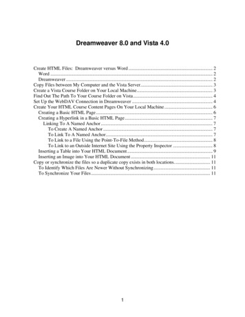
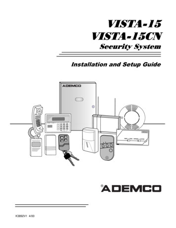
RECOMMENDATIONS FOR PROPER PROTECTIONThe Following Recommendations for the location of Fire and Burglary DetectionDevices Help Provide Proper Coverage for the Protected Premises.Recommendations for Smoke and Heat DetectorsWith regard to the number and placement of smoke/heat detectors, we subscribe to the recommendationscontained in the National Fire Protection Association's (NFPA) Standard #72 noted below.Early warning fire detection is best achieved by the installation of fire detection equipment in all roomsand areas of the household as follows: For minimum protection, a smoke detector should be installedoutside of each separate sleeping area and on each additional floor of a multi-floor family living unit,including basements. The installation of smoke detectors in kitchens, attics (finished or unfinished), orin garages is not normally recommended.For additional protection, the NFPA recommends that you install heat or smoke detectors in the livingroom, dining room, bedroom(s), kitchen, hallway(s), attic, furnace room, utility and storage rooms,basements, and attached garages.In addition, we recommend the following: Install a smoke detector inside every bedroom where a smoker sleeps. Install a smoke detector inside every bedroom where someone sleeps with the door partly orcompletely closed. Smoke could be blocked by the closed door. Also, an alarm in the hallway outsidemay not wake up the sleeper if the door is closed. Install a smoke detector inside bedrooms where electrical appliances (such as portable heaters, airconditioners, or humidifiers) are used. Install a smoke detector at both ends of a hallway if the hallway is more than 40 feet (12 meters) long. Install smoke detectors in any room where an alarm control is located, or in any room where alarmcontrol connections to an AC source or phone lines are made. If detectors are not so located, a firewithin the room could prevent the control from reporting a fire or an intrusion.THIS CONTROL COMPLIES WITH NFPA REQUIREMENTS FORTEMPORAL PULSE SOUNDING OF FIRE NOTIFICATION APPLIANCES. KITCHEN DINING BEDROOM BEDROOMTV ROOM KITCHEN DINING LIVING ROOM BDRMBDRM BEDROOMBEDROOMLIVING ROOM Smoke Detectors for Minimum Protection Smoke Detectors for Additional Protection Heat-Activated Detectors BEDROOM BEDROOMTOBRBEDROOM KTCHN.LVNG RM CLOSEDDOORGARAGEBASEMENTRecommendations for Proper Intrusion ProtectionFor proper intrusion coverage, sensors should be located at every possible point of entry to a home orcommercial premises. This includes skylights and upper windows in a multi-level building.In addition, we recommend that radio backup be used in a security system so that alarm signals can still besent to the alarm monitoring station in the event that the telephone lines are out of order (alarm signals arenormally sent over the phone lines, if connected to an alarm monitoring station).iii
Table of Contents Conventions Used In This Manual . viiiSECTION 1. Introduction .1–1Description .1–1Features.1–1SECTION 2. Installing the Control .2–1Mounting the Cabinet .2–1Installing the Lock (if used) .2–1Mounting the Control's Circuit Board Alone in the Cabinet .2–2Mounting Control and RF Receiver Circuit Boards Together in the Cabinet .2–3Standard Phone Line Connections .2–4Wiring the AC Transformer .2–5Installing the Backup Battery .2–6Earth Ground Connections .2–6SECTION 3. Installing Remote Keypads.3–1Keypads That May Be Used.3–1Wiring to the Keypads.3–1Mounting the Keypads .3–2Supplementary Power for Additional Keypads .3–2Preliminary Checkout Procedure .3–3SECTION 4. Basic Hardwired Zones 1–6 .4–1Installing the Hardwired Zones.4–1Programming Hardwired Zones .4–4Checkout Procedure for Hardwired Zones .4–4SECTION 5. Wired Zone Expansion.5–1Installing Zone Expansion Units .5–1Connections and Setup.5–1Programming Wired Expansion Zones.5–3Checkout Procedure for Wired Expansion Zones .5–3SECTION 6. Wireless Expansion (5800 System).6–1About Wireless Expansion .6–1Installing the 5881/5882 Receiver .6–2Installing the 5800TM Module .6–3Jam Detection and Reporting .6–3About 5800 Series Transmitters .6–3Installing 5800 Series Transmitters.6–7SECTION 7. Relay Outputs & Powerline Carrier Devices .7–1About Relays and Powerline Carrier Devices .7–14204 and 4229 Relay Modules .7–1Powerline Carrier Devices .7–3Programming Relay Outputs .7–4SECTION 8. 4285 & 4286 VIP Module .8–1About the 4285 & 4286 VIP (Voice Interactive Phone) Module.8–1Installing the VIP Module.8–1Programming the 4285/4286 VIP Module .8–4Checking 4285/4286 VIP Module Operation .8–4SECTION 9. External Sounders .9–1Compatible Sounders.9–1NFPA Requirements.9–1Sounder Connections and Power .9–2Sounder Supervision .9–2Testing the Sounder .9–2iv
Table of ContentsSECTION 10. Long Range Radio .10–1About Long Range Radio.10–1Wiring Connections .10–1Dynamic Signaling Feature .10–2SECTION 11. Audio Alarm Verification (AAV) Unit .11–1About Audio Alarm Verification .11–1Wiring Connections .11–1SECTION 12. Final Power-Up .12–1Earth Ground Connections .12–1AC Power-Up .12–1Connecting the Backup Battery.12–1Battery Tests.12–2SECTION 13. Mechanics of Programming .13–1About Programming .13–1Entering Program Mode.13–2Programming a Data Field.13–2Reviewing a Data Field/Erasing an Entry .13–2Interactive Mode Programming ( 56, 58, 80, 81, and 82).13–2Loading Factory Defaults.13–3Programming System Setup Fields .13–3Exiting the Programming Mode .13–3SECTION 14. Zone Response Type Definitions.14–1Zone Type Definitions.14–1SECTION 15. Data Field Descriptions.15–1Descriptions of System Data Fields.15–1SECTION 16. Zone Programming.16–1About Zone Programming .16–1 56 Zone Programming Procedures.16–1 58 Expert Programming Mode Procedures .16–4To Remove a Zone .16–6To Delete and Replace a Transmitter Serial Number.16–7To Enter and Duplicate Wireless Keys .16–7SECTION 17. Output Device Programming.17–1Programming Options Defined .17–1Programming Output Relays and Powerline Carrier Devices.17–3SECTION 18. Zone Lists.18–1About Zone List Menu Mode .18–1Zone List Displays .18–1Cross Zoning - Zone List 04.18–2NIGHT-STAY - Zone List 05 .18–2SECTION 19. Alpha Descriptor Programming.19–1About Alpha Descriptor Programming.19–1Zone Descriptors .19–1Programming Zone Descriptors (Program Menu Mode 82) .19–1Adding Custom Words/Numbers (not annunciated by the 4285/4286 VIP Module) .19–3SECTION 20. Remote Programming and Control (Downloading) .20–1About Remote Programming.20–1Equipment Required .20–1Initial Download .20–2Remote Programming Commands.20–2Remote Programming Advisory Notes .20–2SECTION 21. System Communication.21–1Panel Communication with Central Station.21–1Report Code Formats.21–1v
VISTA-15/VISTA-15CN Installation & Setup GuideSECTION 22. System Operation .22–1Security Codes .22–1Keypad Functions .22–2Setting the Real-Time Clock .22–6SECTION 23. Testing the System .23–1Test Procedure .23–1SECTION 24. Troubleshooting Guide.24–1SECTION 25. Specifications & Accessories.25–1Specifications .25–1Accessories (Compatible Devices) .25–3APPENDIX A 5800 RF System Wireless Transmitters. A–1Transmitter Input Loop Identification. A–1APPENDIX B Regulatory Agency Statements. B–1APPENDIX C Warnings and Limitations . C–1Index.Index-1Programming Form . Insertvi
List of Figures Figure 1. Installing the Cabinet Lock.2–1Figure 2. Mounting the PC Board.2–2Figure 3. Mounting the PC Board and RF Receiver Together in the Cabinet .2–3Figure 4. Telephone Line Connections .2–4Figure 5. Connections of 4300 Transformer to the Control Board .2–5Figure 6. Keypad Connections to the Control Board.3–2Figure 7. Using a Supplementary Power Supply for Keypads .3–3Figure 8. 2-Wire Smoke Detector Connected to Zone 1.4–2Figure 9. 4-Wire Smoke Detector Connections (Zones 2–6) .4–3Figure 10. Wiring Connections - 4219 Expansion Module .5–2Figure 11. Wiring Connections - 4229 Expansion/Relay Module.5–2Figure 12. 5881/5882 RF Receiver (cover removed).6–2Figure 13. 4229 Connections to Control .7–2Figure 14. 4204 Connections to Control .7–3Figure 15. 4300 Transformer Wiring Connections .7–4Figure 16. 4285/4286 VIP Module Wiring Connections .8–3Figure 17. Typical Sounder Wiring.9–2Figure 18. Bell Supervision Wiring .9–2Figure 19. Long Range Radio Connections .10–1Figure 20. Connection of AAV Unit When Not Using a 4285/4286 VIP Module .11–2Figure 21. Connection of AAV Unit When Also Using a 4285 or 4286 VIP Module.11–2Figure 22. VISTA-15/VISTA-15CN Summary of Connections. Inside Back Covervii
Conventions Used In This Manual Before you begin using this manual, it is important that you understand the meaning of the followingsymbols:ULA UL note that includes specific information that must be followed if you are installing this systemin a UL Listed application.A note that includes specific information that must be followed if you are installing this system in aCanadian UL Listed application.A checked note includes information you should be aware of before continuing with theinstallation, and which, if not observed, could result in operational difficulties.This symbol warns of conditions that could seriously affect the operation of the system, or causedamage to the system. Please read each warning carefully. This symbol also denotes warningsabout physical harm to the user.Enter Zone Num.(00 Quit) 00You may program many system options by responding to alpha keypad displayprompts. These prompts are shown in a double-line box.When programming the system, data fields are indicated by a “star” ( ) followedby the data field number.PRODUCT MODEL NUMBERS: Unless noted otherwise, references to specific model numbers representADEMCO products.viii
S E C T I O N1Introduction In This Section Description Features DescriptionThe VISTA-15/VISTA-15CN is a security system control that supports up to 32 zones,including six basic hardwired zones (1 through 6) and a maximum of 26 expansion zones.These expansion zones may include up to eight hardwired zones, or up to 26 wireless zones ifhardwired zones are not used. Three separate keypad-activated zones are also provided.FeaturesBasic Hardwired ZonesProvides 6 basic hardwired zones having the following characteristics: EOLR supervision supporting N.O. or N.C. sensors Programmable response time (10, 350, or 700 milliseconds) Up to sixteen 2-wire smoke detectors on zone 1 4-wire smoke or heat detectors on zones 2 through 6 (as many as can be powered fromAuxiliary Power on the control).Optional Expansion Zones (26 total: up to 8 wired with 18 wireless, OR 26 wireless)Wired Expansion:Supports up to 8 additional wired zones using a 4219 Expansion Module or 4229Expansion/Relay Module. These zones have the following characteristics: EOLR supervision supporting N.O. or N.C. sensors 300-500mSec normal response with an option for fast (10-15mSec) response on loop A (firstexpansion zone).Wireless Expansion:Supports up to 26 wireless zones (fewer if using wired expansion zones). Requires the use of a 5881 (5882 in Canada) type RF receiver, as indicated below:Receiver Model5881L/5882L5881M/5882M5881H/5882HNo. of ZonesUp to 8Up to 16Up to 26 Requires the use of 5800 Series Wireless Transmitters.Remote KeypadsUp to 4 of any of the following keypads may be used in the installation:Fixed-word keypad:6128, 6128RFAlpha keypad:6139 (2-line alphanumeric display)1–1
VISTA-15/VISTA-15CN Installation and Setup GuideSecurity Codes Supported One Installer code for entire system (user 1) One Master code for entire system (user 2) 12 Secondary User codes (users 3–14) One Temporary code (user 15) One Duress code (user 16).Temporary Code: A special code that can be used to disarm and arm the system until the Mastercode is entered.Duress Code: An emergency code that, when entered by any user to disarm or arm the system,sends a silent duress message to the Central Station.Keypad Panic Features Up to 3 programmable panic key functions provided Designated as zones 95, 96, 99 Activated by wired and wireless keypads Distinguished by subscriber ID number.Zone Monitor Features Provides automatic high loop resistance detection on hardwired zones 2–6, and displays aCHECK message for the affected zone when the system is in the disarmed state. Contains a Hardwire Short Detection circuit for zones 1-6 †, and enabled in 30. Detecting ashort in any wired zone, it sends a sensor Trouble message to the Central Station when thesystem is in the disarmed state. At the same time a CHECK message is displayed on thekeypad.†Hardwire Short Detection is disabled on any zone programmed for FIRE (Zone type 09).Either condition (high resistance or short) detected on any zone, prevents the system frombeing armed until the offending condition is cleared. Conversely, when the system is armed,and these conditions occur, an alarm is generated.Exit Error False Alarm Prevention Features Enables the system to determine the difference between an actual alarm and an alarmcaused by leaving an entry/exit or interior zone open after the Exit Delay expires. If notdisarmed in time, an alarm sounds and an Exit Error report is sent to the Central Station.An exit alarm condition also occurs if an entry/exit or interior zone re-opens within 2minutes after the end of an Exit Delay. The system provides an automatic Exit Delay Reset feature that allows the user to exit(fault), close the door (restore the fault), then re-enter (fault again) the premises within theexit delay time period. Upon re-entering, a new exit delay time period is begun with thekeypad annunciating three rapid beeps. This feature only resets the exit delay time oncefor each arming session.Optional Output Relays and Powerline Carrier Devices (X10 type)The VISTA-15/VISTA-15CN supports the following optional output relays and PowerlineCarrier devices (X10 type): Maximum of 4 output devices Up to 4 relays using one 4204 Relay Module
The VISTA-15/VISTA-15CN is a security system control that supports up to 32 zones, including six basic hardwired zones (1 through 6) and a maximum of 26 expansion zones. These expansion zones may include up to eight hardwired zones, or up to 26 wireless zones if hardwired zones are not used. Three separate keypad-activated zones are also provided.