Transcription
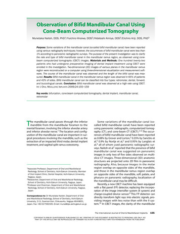
155 Naitoh.qxd1/22/093:12 PMPage 155Observation of Bifid Mandibular Canal UsingCone-Beam Computerized TomographyMunetaka Naitoh, DDS, PhD1/Yuichiro Hiraiwa, DDS2/Hidetoshi Aimiya, DDS2/Eiichiro Ariji, DDS, PhD3Purpose: Some variations of the mandibular canal (so-called bifid mandibular canal) have been reportedusing various radiography techniques; however, the occurrences of bifid mandibular canal were less than1% according to panoramic radiographic surveys. The purpose of the present investigation was to clarifythe rate and type of bifid mandibular canal in the mandibular ramus region, as observed using conebeam computerized tomography (CBCT) images. Materials and Methods: One hundred twenty-twopatients who had undergone preoperative imaging of dental implant treatment using CBCT wereenrolled in the investigation. Two-dimensional (2D) images of various planes in the mandibular ramusregion were reconstructed on a computer using three-dimensional visualization and measurement software. The course of the mandibular canal was observed and the length of the bifid canal was measured. Results: Bifid mandibular canal in the mandibular ramus region was observed in 65% of patientsand 43% of sides. Bifid mandibular canal can be classified into four types: retromolar, dental, forward,and buccolingual canals. Conclusion: Bifid mandibular canal was observed at a high rate using CBCT.INT J ORAL MAXILLOFAC IMPLANTS 2009;24:155–159Key words: bifurcation, cone-beam computerized tomography, dental implant, mandibular canal,retromolarhe mandibular canal passes through the inferiormandible from the mandibular foramen to themental foramen, involving the inferior alveolar arteryand inferior alveolar nerve.1 The location and configuration of the mandibular canal are important in surgical procedures involving the mandible, such as theextraction of an impacted third molar, dental implanttreatment, and sagittal split ramus osteotomy.T1AssociateProfessor, Department of Oral and MaxillofacialRadiology, School of Dentistry, Aichi-Gakuin University; Memberof Oral Implant Clinic, Dental Hospital, Aichi-Gakuin University,Nagoya, Japan.2Researcher, Department of Oral and Maxillofacial Radiology,School of Dentistry, Aichi-Gakuin University, Nagoya, Japan.3Professor and Chairman, Department of Oral and MaxillofacialRadiology, School of Dentistry, Aichi-Gakuin University, Nagoya,JapanCorrespondence to: Dr Munetaka Naitoh, Department of Oraland Maxillofacial Radiology, School of Dentistry, Aichi-GakuinUniversity, 2-11, Suemori-Dori, Chikusa-Ku, Nagoya 464-8651,Japan. Fax: 81-527592165. Email: mune@dpc.aichi-gakuin.ac.jpSome variations of the mandibular canal (socalled bifid mandibular canal) have been reportedusing panoramic radiographs, computerized tomography (CT), and cone-beam CT (CBCT).2–8 The occurrences of bifid mandibular canal have been reportedas 0.08% by Grover and Lorton,3 0.35% by Sancbis etal,5 0.9% by Nortje et al,2 and 0.95% by Langlais etal,4 all of whom used panoramic radiographic surveys. Naitoh et al7 reported that the presence of bifidmandibular canal was suggested on panoramicimages in only two of five sides observed on multislice CT images. Three-dimensional (3D) anatomicstructures are projected onto 2D film in panoramicradiography. Also, because images in the molarregion overlap on opposite sides of the mandible,and those in the mandibular ramus region overlapon opposite sides of the mandible, soft palate, andpharynx on panoramic radiography, localization ofthe mandibular canal may be difficult.Recently, a new CBCT machine has been equippedwith a flat panel (FP) detector, replacing the incorporation of the image intensifier system (II system) andcharge-coupled device sensor.9 This FP detector candirectly transform light rays into electric signals, providing images with less noise than with the II system.10 In CBCT images, the clarity of the mandibularThe International Journal of Oral & Maxillofacial ImplantsCOPYRIGHT 2008 BY QUINTESSENCE PUBLISHING CO, INC. PRINTING OF THIS DOCUMENT IS RESTRICTED TO PERSONAL USE ONLY. NOPART OF THIS ARTICLE MAY BE REPRODUCED OR TRANSMITTED IN ANY FORM WITHOUT WRITTEN PERMISSION FROM THE PUBLISHER155
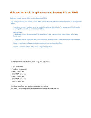
155 Naitoh.qxd1/22/093:12 PMPage 156Naitoh et almandibular canalCbifid canalCFig 1 Reconstruction of the images of longitudinal sections. To reconstruct useful images using OsiriX software, the center of rotation oflongitudinal sections (C) was set at the mandibular foramen in the axial image (left). Then, longitudinal sections were horizontally rotated,and the center was moved buccolingually and postanteriorly by degrees. Moreover, when necessary, longitudinal sections (right) wererotated vertically in cross-sectional images (middle).canal may therefore be improved. The purpose of thepresent investigation was to clarify the rate and typeof bifid mandibular canal observed in the mandibular ramus region using CBCT images.MATERIALS AND METHODSSubjectsA total of 160 patients underwent preoperativeimaging for dental implant treatment between April2007 and December 2007 using CBCT. Seventeenpatients in whom bone blocks were harvested fromthe retromolar region were excluded. Also, 21patients in whom hemilateral or bilateral mandibularforamen/foramina were not included in the exposurefield were excluded. Therefore, a total of 122 patients(88 women and 34 men) were enrolled in this investigation. The mean age was 50.8 years (range 17 to 78years, SD 15.1 years).CBCTA CBCT unit (Alphard VEGA; Asahi Roentgen, Kyoto,Japan) with a FP detector was used. The exposurevolume was set at 102 mm in diameter and 102 mmin height (I-mode), and the voxel size was 0.2 0.2 0.2 mm3 (spatial resolution: 2.5 line pairs/mm). Thescan was set at 80 kV and 5 mA, as recommended bythe manufacturer. The occlusal plane of each patientwas set parallel to the floor base using ear rods and achinrest. DICOM files of axial images were saved to amagneto-optical disk.156Observation of the Mandibular CanalTwo oral and maxillofacial radiologists, with experience of 24 years (MN) and 4 years (HA), reconstructedand observed the images as follows. Two-dimensionalimages of various planes, mainly longitudinal, in themandibular ramus region were reconstructed on acomputer (Macintosh G4, Apple Computer, Cupertino,CA) using 3D visualization and measurement software(OsiriX, OsiriX Foundation, Geneva, Switzerland).11 Onthe display, the center of rotation of longitudinal sections was initially set at the mandibular foramen inaxial images. Then, longitudinal sections were rotatedhorizontally, and the center was moved buccolingually and postanteriorly by degrees. Moreover, whennecessary, longitudinal sections were rotated vertically in cross-sectional images (Fig 1). The density andcontrast of images were adequately adjusted to clarifythe mandibular and bifid mandibular canals. Subsequently, the course of the mandibular canal wasobserved and the bifid mandibular canal was classified. Further, the length of the bifid canal was measured. When a secondary bifurcation of the bifid canalwas observed, the longer secondary canal wasselected for classification and measurement.Statistical AnalysisDifferences in the rate of bifid mandibular canal presence between men and women were evaluatedusing chi-square statistics. Also, differences in lengthbetween types of bifid canals were evaluated usingthe Mann-Whitney U test. Differences were considered significant at P .05.Volume 24, Number 1, 2009COPYRIGHT 2008 BY QUINTESSENCE PUBLISHING CO, INC. PRINTING OF THIS DOCUMENT IS RESTRICTED TO PERSONAL USE ONLY. NOPART OF THIS ARTICLE MAY BE REPRODUCED OR TRANSMITTED IN ANY FORM WITHOUT WRITTEN PERMISSION FROM THE PUBLISHER
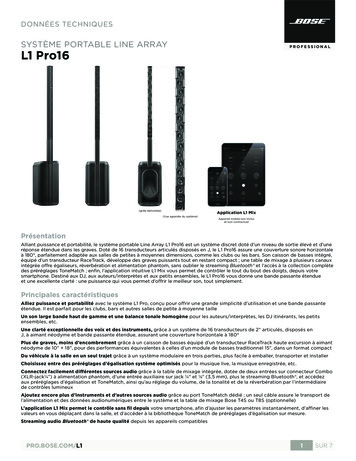
155 Naitoh.qxd1/22/093:12 PMPage 157Naitoh et alFig 2Classification of bifid mandibular canals.Fig 2a Retromolar canal (type 1) in a 69year-old man. The retromolar canal, whichbifurcated from the mandibular canal in theright mandibular ramus region, courses forward at first, reaching the retromolar regionafter the crook (white arrowheads).Fig 2b Dental canal (type 2) in a 53-yearold woman. The dental canal, which bifurcated from the mandibular canal in theright mandibular ramus region, coursed forward, reaching the root apex of the thirdmolar (white arrowheads).Fig 2c Forward canal without confluence(type 3) in a 72-year-old woman. The forward canal, which bifurcated from themandibular canal in the left mandibularramus region, coursed forward to the second molar region (white arrowheads).Fig 2d Forward canal with confluence(type 3) in a 57-year-old man. The forwardcanal, which bifurcated from the mandibular canal in the right mandibular ramus,coursed anteriorly and then joined up withthe main mandibular canal (white arrowheads).Fig 2e Lingual canal (type 4) in a 59-yearold man. The lingual canal, which bifurcated from the mandibular canal in theright mandibular ramus, coursed linguallyand then penetrated through the lingualcortical bone (white arrowhead).Fig 2f Buccal canal (type 4) in a 51-yearold woman. The buccal canal, which bifurcated from the mandibular canal in theright mandibular ramus, coursed buccoinferiorly (white arrowhead).RESULTSBifid mandibular canals in the mandibular ramusregion were observed in 79 of the 122 patients (55women and 24 men; 64.8% of the population) and 105of 244 sides (43.0%). There was no significant difference between genders. One bifid canal was observedin 96 sides, and two canals were seen in nine sides.One hundred twelve of 114 bifid canals originatedfrom the superior wall of the mandibular canal, oneoriginated from the buccal wall, and one originatedfrom the lingual wall. Thus, the bifid mandibular canalcould be classified into four types: type 1 retromolar canal; type 2 dental canal (second and thirdmolars); type 3 forward canal with/without confluence to the main mandibular canal; and type 4 buccolingual canal (Fig 2). The retromolar canal (type 1)was defined as such when the foramen of the canalwas observed on the bone surface of the retromolarregion. The dental canal (type 2) was classified whenthe end of the canal reached to the root apex of thesecond or third molar. The other bifid canal (type 3)arising from the superior wall of the mandibularcanal was defined as the forward canal. The forwardcanal was included with/without confluence to themain mandibular canal. The buccolingual canal (type4) was defined as a bifid canal arising from the buccalor lingual wall of the mandibular canal.The International Journal of Oral & Maxillofacial ImplantsCOPYRIGHT 2008 BY QUINTESSENCE PUBLISHING CO, INC. PRINTING OF THIS DOCUMENT IS RESTRICTED TO PERSONAL USE ONLY. NOPART OF THIS ARTICLE MAY BE REPRODUCED OR TRANSMITTED IN ANY FORM WITHOUT WRITTEN PERMISSION FROM THE PUBLISHER157
155 Naitoh.qxd1/22/093:12 PMPage 158Naitoh et alTable 1Rate of Bifid Mandibular Canal PresenceClassification1:2:3:4:Retromolar canalDental canalForward canalBuccolingual canalIn all patients (%)In all sides (%)25.47.444.31.613.54.127.90.8Table 2 Rate of Different Types of BifidMandibular Canal in 114 Bifid CanalsClassification1: Retromolar canal2: Dental canalThird molarSecond molar3: Forward canalWith confluenceWithout confluence4: Buccolingual canalNo. of canalsRate (%)24108268563229.88.87.01.859.64.555.31.8The results regarding the types of bifurcations areshown in Tables 1 and 2. In nine sides with two bifidcanals each, types 1 and 2 were observed in onepatient, types 1 and 3 in one patient, types 2 and 3 intwo patients, and types 3 and 3 in five patients. Theretromolar canal was observed in 34 of 114 bifidmandibular canals (29.8%), dental canal in 10 canals(8.8%), forward canal in 68 canals (59.6%), and buccolingual canal in two canals (1.8%). The mean length ofbifid canals was 1.48 cm (range: 0.72 to 2.45 cm) inretromolar canals, 0.89 cm (range: 0.16 to 2.30 cm) indental canals, 0.96 cm (range: 0.14 to 2.50 cm) in forward canals, and 0.16 cm (range: 0.15 to 0.17 cm) inbuccolingual canals. Significant differences in lengthwere noted between the retromolar canal and theother types and between the forward and buccolingual canals. The dental canal reached to the rootapex of the second molar in two canals and the thirdmolar in eight canals.DISCUSSIONThe location and configuration of mandibular canalvariations are important in dental implant treatment.In panoramic image surveys, the occurrence of bifidmandibular canal presence was reported to rangefrom 0.08% to 0.95%.2–5 On CBCT images, however,bifurcation was observed in 65% of patients. Thereare obvious limitations in identifying the occurrenceof a bifid mandibular canal via the observation of 2Dpanoramic images. Recently, some cases with a bifid158mandibular canal have been identified using CT orCBCT. Bifid mandibular canal presence might beobserved in detail using CBCT. CBCT has some majoradvantages regarding image quality compared to CT.The voxel size is small (0.2 0.2 0.2 mm3), and inCT the slice thickness is thicker (0.5 to 1.0 mm). Also,radial metal artifacts, which are often observed at thelevel of the occlusal plane in CT, greatly hamperobservation of the bifid mandibular canal in themandibular ramus. In the present study, the exposurevolume (field of view) was selected as 102 mm indiameter and 102 mm in height to include the designated implant site and anterior region of the mandibular ramus for harvesting bone blocks. Iwai et al12reported that the effective dose of the same exposurevolume in Alphard units was 0.13 mSv using the 2005International Commission on Radiological Protection(ICRP) tissue-weighting factors. Ludlow et al 13reported that the effective dose using the 2007 ICRPrecommendations for CBCT exposure was 3 to 28times higher than the average dose for a panoramicradiograph. Also, the effective doses of CT for eachjaw were recommended to be less than 0.5 mSv usingthe 1990 ICRP recommendations. 14 MacDonaldJankowski and Orpe15,16 reported that a higher spatial resolution and lower radiation dose could beachieved using a smaller exposure volume. An adequate exposure volume has to be selected accordingto the purpose of imaging diagnosis.The bifid mandibular canal was classified into fourtypes using CBCT images and previous radiographicand anatomic studies.2,4,16 The classification of bifidcanals, especially retromolar (type 1) and dental(type 2), may be clinically important. Within the retromolar canal, the artery branched from the inferioralveolar artery, and nerves derived from the inferioralveolar nerve trunk were observed.17,18 Kodera andHashimoto 18 reported that the retromolar nervebranched off to the buccal mucosa and the buccalgingiva of the mandibular premolar and molarregions in a Japanese cadaver. Recently, the retromolar region was used as a donor site for harvestingbone blocks.19–21 To safely harvest bone blocks fromthe retromolar region, preoperative imaging usingCBCT may be needed. Also, the identification of dental canal presence may be important in extractionand root canal treatment of teeth.The rate of occurrence in the retromolar foramina/canal ranged from 12% to 33% of mandibles onmacroscopic observation in previous reports.18,22,23 InCBCT images, a retromolar canal (type 1) wasobserved in 25.4% of patients and 13.5% of sides.The occurrence rate in CBCT images was similar tothat seen in dry mandibles. The internal diameter ofthe retromolar foramen was reported to range fromVolume 24, Number 1, 2009COPYRIGHT 2008 BY QUINTESSENCE PUBLISHING CO, INC. PRINTING OF THIS DOCUMENT IS RESTRICTED TO PERSONAL USE ONLY. NOPART OF THIS ARTICLE MAY BE REPRODUCED OR TRANSMITTED IN ANY FORM WITHOUT WRITTEN PERMISSION FROM THE PUBLISHER
155 Naitoh.qxd1/22/093:12 PMPage 159Naitoh et al0.2 mm to more than 1.0 mm.18 In CBCT images, themean length of retromolar canals was 1.6 cm, andthe retromolar canal in many cases coursed forwardfrom the bifurcated point at first, and then coursedposteriorly and superiorly after the crook, reachingthe retromolar region. A forward canal of more than2.0 cm, which was observed in eight canals, reachesnear to the second molar region. A forward canalconfluent with the main mandibular canal (type 3),which was observed in 7% of forward canals, wasconsidered similar to the type reported usingpanoramic images by Langlais et al.4Further studies are needed to characterize themental foramen, mandibular incisive canal, genialspinal bony canal, and mylohyoid sulcus in detailusing CBCT images.CONCLUSIONBifid mandibular canal presence was observed at ahigh rate (65% of patients) using CBCT, and the retromolar canal was observed in 25% of patients.ACKNOWLEDGMENTWe thank Dr A. Katsumata from the Asahi University School ofDentistry for his advice regarding the analysis of CBCT images.REFERENCES1. Clemente CD. Cranial nerves. In: Gray H (ed). Anatomy of theHuman Body, ed 30. Philadelphia: Lea & Febiger,1985:1165–1169.2. Nortje CJ, Farman AG, Grotepass FW. Variations in the normalanatomy of the inferior dental (mandibular) canal: A retrospective study of panoramic radiographs from 3612 routinedental patients. Br J Oral Surg 1977;15:55–63.3. Grover PS, Lorton L. Bifid mandibular nerve as a possiblecause of inadequate anesthesia in the mandible. J OralMaxillofac Surg 1983;41:177–179.4. Langlais RP, Broadus R, Glass BJ. Bifid mandibular canals inpanoramic radiographs. J Am Dent Assoc 1985;110:923–926.5. Sancbis JM, Penarroba M, Soler F. Bifid mandibular canal.J Oral Maxillofac Surg 2003;61:422–424.6. Claeys V, Wackens G. Bifid mandibular canal: Literature reviewand case report. Dentomaxillofac Radiol 2005;34:55–58.7. Naitoh M, Hiraiwa Y, Aimiya H, et al. Bifid mandibular canal.Implant Dent 2007;16:24–32.8. Rouas P, Nancy J, Bar D. Identification of double mandibularcanals: Literature review and three case reports with CT scansand cone beam CT. Dentomaxillofac Radiol 2007;36:34–38.9. Naitoh M, Hirukawa A, Katsumata A, Saburi K, Okumura S, ArijiE. Imaging artifact and exposure conditions in limited-volumecone-beam computed tomography: Comparison between animage intensifier system and a flat panel detector. Oral Radiol2006;22:69–74.10. Baba R, Ueda K, Okabe M. Using a flat-panel detector in highresolution cone-beam CT for dental imaging. DentomaxillofacRadiol 2004;33:285–290.11. Rosset A, Spadola L, Ratib O. OsiriX: An open-source softwarefor navigating in multidimensional DICOM images. J DigitImag 2004;17:205–216.12. Iwai K, Nishizawa K, Mishima A, Kobayashi K. Estimation of aneffective dose of a subject by X-ray computed tomographydevice 3DCT Alphard 3030 [in Japanese]. Abstracts and program, the 48th Annual Congress of Japanese Society for Oraland Maxillofacial Radiology, 2007:66.13. Ludlow JB, Davies-Ludlow LE, Mol A. Dosimetry of recentlyintroduced CBCT units for oral and maxillofacial radiology.Abstracts and program, 16th International Congress ofDentomaxillofacial Radiology, 2007:97.14. Harris D, Buser D, Dula K, et al. EAO guidelines for the use ofdiagnostic imaging in implant dentistry. Clin Oral ImplantsRes 2002;13:566–570.15. MacDonald-Jankowski DS, Orpe EC. Computed tomographyfor oral and maxillofacial surgeons. Part 2: Cone-beam computed tomography. Asian J Oral Maxillofac Surg 2006;18:85–92.16. MacDonald-Jankowski DS, Orpe EC. Some current legal issuesthat may affect oral and maxillofacial radiology. Part 2: Digitalmonitors and cone-beam computed tomography. J Can DentAssoc 2007;73:507–511.17. Carter RB, Keen EN. The intramandibular course of the inferioralveolar nerve. J Anat 1971;108:433–440.18. Kodera H, Hashimoto I. A case of mandibular retromolar canal:Elements of nerves and arteries in this canal [in Japanese].Kaibougaku Zashi 1995;70:23–30.19. Khoury F. Augmentation of the sinus floor with mandibularbone block and simultaneous implantation: A 6-year clinicalinvestigation. Int J Oral Maxillofac Implants 1999;14:557–564.20. Yildirim M, Spiekermann H, Handt S, Edelhoff D. Maxillary sinusaugmentation with the xenograft Bio-Oss and autogenousintraoral bone for qualitative improvement of the implantsite: A histologic and histomorphometric clinical study inhumans. Int J Oral Maxillofac Implants 2001;16:23–33.21. Nkenke E, Radespiel-Troger M, Witfang J, Schultze-Mosgau S,Winkler G, Neukam FW. Morbidity of harvesting of retromolarbone grafts: A prospective study. Clin Oral Impl Res 2002;13:514–521.22. Lofgren AB. Foramina retromolaria mandibulae: A study onhuman skulls of nutrient foramina situated in the mandibularretromolar fossa. Odont Tidskr 1957;65:552–570.23. Sagne S, Olsson G, Hollender L. Retromolar foramina andcanals in the human mandible. Dentomaxillofac Radiol1977;6:41–45.The International Journal of Oral & Maxillofacial ImplantsCOPYRIGHT 2008 BY QUINTESSENCE PUBLISHING CO, INC. PRINTING OF THIS DOCUMENT IS RESTRICTED TO PERSONAL USE ONLY. NOPART OF THIS ARTICLE MAY BE REPRODUCED OR TRANSMITTED IN ANY FORM WITHOUT WRITTEN PERMISSION FROM THE PUBLISHER159
and 43% of sides. Bifid mandibular canal can be classified into four types: retromolar, dental, forward, and buccolingual canals. Conclusion: Bifid mandibular canal was observed at a high rate using CBCT. INT J ORAL MAXILLOFAC IMPLANTS 2009;24:155-159 Key words: bifurcation, cone-beam computerized tomography, dental implant, mandibular canal .