Transcription
SRC PlusResidential/Light CommercialIrrigation ControllerOwner’s Manual andProgramming Instructions600i 6-station Indoor Model601i 6-station Indoor Model(International)900i 9-station Indoor Model901i 9-station Indoor Model(International) Plus
TABLE OF CONTENTS .INTRODUCTION AND INSTALLATIONIntroduction . 1SRC Plus Components . 2-3Mounting Controller to Wall . 4Connecting Valves and Transformer . 5Connecting the Battery . 6Connecting a Master Valve . 6Connecting a Pump Start Relay . 7Connecting a Weather Sensor . 8Weather Sensor Bypass . 8Connecting a SRR or ICR Remote Control . 9Connecting to IMMS Central Control System . 10Power Failures . 10CONTROLLER PROGRAMMING AND OPERATIONSprinkler System Fundamentals . 11Creating a Watering Schedule . 12How to Fill Out the Watering Schedule Form . 12Watering Schedule Form (Example) . 13Watering Schedule Form . 14Programming Fundamentals . 15Programming Fundamentals (Example) . 16
TABLE OF CONTENTS (continued) .Programming the Controller . 17Setting the Date and Time . 18Setting Program Start Times . 18Eliminating a Program Start Time . 19Setting Station Run Times (Length of Watering for Each Area) . 19Setting Days To Water . 20Selecting Specific Days of the Week to Water . 20Selecting Odd or Even Days . 20Run . 20System Off . 21Manually Run a Single Station . 21Manually Run All Stations . 21One Touch Manual Start and Advance . 22Hunter Quick Check . 22Clearing Controller's Memory / Resetting the Controller . 22TROUBLESHOOTING AND SPECIFICATIONSTroubleshooting Guide . 23-24Specifications . 25FCC Notice . Back Cover
INTRODUCTION .Finally, there’s an affordable controller for your home.Hunter Industries is pleased to present the SRC Plus – a Simple and Reliable Controller for residential applications. Designed with the needs of thecustomer in mind, the SRC Plus offers simplified dial programming and an impressive range of features typically found in controllers costing twiceas much.While it’s affordable, the SRC Plus is without a doubt a professional grade product. The controller’s large, handsome cabinet, complete with aprotective door, provides your controller with a neat and professional appearance. And, the SRC Plus is filled with the essential features thatlandscapes demand (like a rain sensor bypass circuit and primary power surge protection), but without some of the unnecessary frills that often leadto contractor call back.The SRC Plus is so easy to use that after reading this User Guide thoroughly, you will need it very little after installation. We have also included anabbreviated instruction sheet inside the door of the controller for quick reference later on. After a few uses of this controller, you can be sure theSRC Plus is a product that does the job efficiently and economically.The SRC Plus is an improved version of the original SRC Plus. Additional features and improvements include: Non-volatile memory More robust circuitry One touch manual start and advance Hunter Quick Check Automatic Short Circuit Protection1
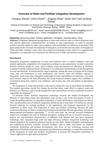
SRC PLUS COMPONENTS .ASTATIONPROGRAMABCSTARTTIMES1234RUN TIMEYEARMONTHDAYRUNNINGAMPM24 HRSU MOTUBWETHFR SA EVEN/ODDPlusSTATIONRUN TIMEYEARMONTHDAYRUNNINGAMPM24 HRPROGRAMSTARTTIMESNEXTRUNDCSYSTEM OFFRUN (BYPASS SENSOR)MANUAL – ALL STATIONSSET CURRENT DATE/TIMEMANUAL – SINGLE STATIONSET PROGRAM START TIMESSET DAYS TO WATERERESETAC AC R RS C MV 19 V Battery2SET STATION RUN TIMES23456
This section will give you a brief overview of some of the componentson the SRC Plus faceplate. Each item will be discussed in further detaillater, however this section can be helpful in getting acquainted with thedifferent options available.A – LCD DisplayStart Time – Identifies selected start time (only one start time perprogram is required).D – Control DialA key feature of the SRC Plus is its clear, easy-to-use dial design thatmakes programming a snap. All essential keypad functions are clearlymarked to eliminate the confusion that’s a characteristic of so manyother controllers.Run – Normal dial position for automatic and manual operation.Program Designator – Identifies program in use A, B, or C.Run (Bypass Sensor) – Used to disengage optional weather sensorthat may be wired to your system.Station Number – Identifies currently selected station number.Set Current Date/Time – Allows current date and clock time to be set.LCD Display – Indicates various times and values.Set Program Start Times – Allows 1 to 4 start times to be enabled ineach program.Run Time – Duration of individual stations watering.Year – Current calendar year.Month – Current calendar month.Day – Current calendar day.Running – Indicates when watering is occurring.AM/PM – Arrow differentiates either AM or PM time.24 HR – 24-hour time is available in addition to AM and PM .Day of the Week – Identifies days of the week to water or you canselect to water on odd or even days.(For all above LCD display items, when an arrow cursor is flashing,that is what you are setting.)B – Control ButtonsButton – Increases the selected flashing display.Button – Decreases the selected flashing display.Button – Advances the selected flashing display.Button – Selects program A, B, or C.C – TransformerA 120 VAC Plug-in transformer (included in SRC -600i and 900i models)supplies 24 VAC to the controller.Set Station Run Times – Allows user to set each station run time from0 to 99 minutes.Set Days To Water – Allows user to select individual days to water orto select an odd or even watering schedule, according to the date.Manual – Single Station – Allows user to activate a one time wateringof a single station.Manual – All Station – Allows user to activate a one time watering ofall stations or a few selected stations.System Off – Allows user to discontinue all programs and stop allwatering until dial is returned to the RUN position.E – Wiring CompartmentReset Button – This button will reset the controller. All programmeddata will remain intact.9-Volt Battery – The alkaline battery will maintain the controllermemory if power to the transformer is disconnected. However, thebattery will not operate any of the watering activity (not included).Transformer – The two wires from the plug-in transformer areconnected to the two AC terminals.Terminal Strip Area – Use to attach transformer and valve wires fromtheir source to the controller.3
MOUNTING CONTROLLER TO WALL .NOTE: The SRC Plus is not water or weather resistant.The controller must me installed indoors or in aprotected area.A1. Select a location as close as possible to a standard electrical outlet,one that is not controlled by a light switch. The location should beprotected from moisture and direct sunlight.B2. Remove the mounting bracket (A) from the back of the controllerhousing by pulling the bracket down and slightly away fromthe unit.3. Place the mounting bracket slightly below eye level. Using the holeat the top and the slide cutout at the bottom, secure the bracket withthe 1" (25mm) screws (B) provided. Note: Install screw anchors ifattaching mounting bracket to drywall or masonry.4. Align slotted openings on back of controller housing (C) with railson the mounting bracket (D). Gently slide the controller down intoposition on the bracket.5. Secure controller in place by installing a screw through the lowercentral mounting hole.4DC
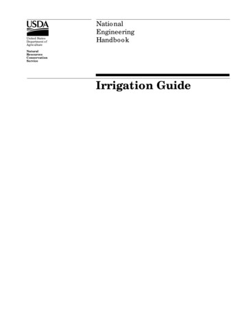
CONNECTING VALVES AND TRANSFORMER .1. Route control wires between control valve location and controller.Typically it is recommended that an 18 AWG multi-wire sprinklerconnection cable be used. This type of connection is insulated forburial and is color-coded to help keep track of your connections.6. Secure the white valve common wire to the screw on the terminalmarked C. With the valve common wire connected, connect thecolor-coded wires from the valves to their appropriate stationnumbers and tighten the screws.2. At the valves, attach the common wire to either solenoid wire of thevalve. This is most commonly the white colored wire. Attach aseparate control wire to the remaining solenoid wire and make anote of the color corresponding to each valve and the wateringstation it controls.7. Route transformer cable through the small hole in the bottom of thecabinet and connect the wires to the two screws marked AC.NOTE: Do not plug transformer into power sourceuntil the controller is mounted and all valves havebeen connected.3. Secure the wires with a waterproof wire connector to protectthe connection.4. Open hinged wiring compartment door to access the terminal striparea shown in the diagram.Valve 45. Route the valve wires through the large opening on the base of thecabinet or through ½ inch conduit if installed. Strip ¼ inch ofinsulation from ends of all wires.Valve 3TransformerRESETAC AC R RS C MV 12345Valve 269 V BatteryValve 1Connect the TwoTransformer Wires tothe Two AC TerminalsValve WiresValve Common Wire5
CONNECTING THE BATTERY.The battery allows you to program the SRC Plus Controller withouthaving AC power available. However, the battery will not be able toactivate any of the station valves. Electrical power must resume beforewatering will continue. The SRC Plus has non-volatile memory whichretains all program information in the event of a power outage.RESETAC AC R RS C MV 1234569 V BatteryWire ClipBattery CompartmentCONNECTING A MASTER VALVE .Valve 4NOTE: Complete this section only if you havea master valve installed. A master valve is anormally closed valve installed at the supplypoint of the main line that opens only whenthe automatic system is activated.1. At the Master Valve, attach the common wire to eithersolenoid wire of the valve. Attach a separate control wire tothe remaining solenoid wire and make a note of the colorcorresponding to the master valve.RESETAC AC R RS C MV 123456Valve 39 V BatteryMaster Valve Wire2. Route these wires to the controller the same way as thestation valves. The white common wire will still go to thescrew slot marked C. The additional wire coming from themaster valve will go in the screw slot marked MV.Valve 2Valve 1Valve WiresMaster ValveValve Common Wire6
CONNECTING A PUMP START RELAY .NOTE: Complete this section only if you have a pumpstart relay installed. A pump start relayis an electronic device that uses a current from thecontroller to actuate a separate electrical circuit toenergize a pump to provide water to your system.The controller should be mounted at least 15 feet (4.5m) away from boththe pump start relay and the pump. When a pump start relay comes on itsends out surges that may potentially cause damage to a controller thatis mounted to close. When a pump is to be operated by the controller, apump start relay must be used. Hunter offers a full range of pump startrelays for most applications.PSR SeriesPump Start RelayPlus15' Minimum (4.5 m)To Pump1. Route a wire pair from the pump relay into the controller housing.2. Connect common wire to the screw slot C (Common) and theremaining wire from the pump relay to the MV screw slot.Relay current draw must not exceed .35 Amps. Do not connectcontroller directly to pump – damage to controller can result.NOTE: If a rain sensor is installed with your SRC Plus,along with a pump start relay, follow instructions onpage 8.7
CONNECTING A WEATHER SENSOR .Weather Sensor BypassA Hunter Mini-Clik rain sensor can be connected to the SRC Plus.The purpose of this sensor is to stop watering when precipitation issufficient. The sensor connects directly to the controller and allowsyou to easily override the sensor by using the RUN (BYPASS SENSOR)position on the dial.RUN (BYPASS SENSOR)With this built-in feature, there isno need for an additional manualbypass switch when using rainsensors The SRC Plus works withthe Hunter Mini-Clik , Rain-Clik ,Freeze-Clik plus some other rain,wind or freeze sensors on the market today. If the sensor is preventingsystem operation, just turn the dial to RUN (BYPASS SENSOR) and theweather sensor will be overridden.1. Route the wires from the rain sensor up through the same openingused for valve wiring.2. Connect one rain sensor wire to the RS terminal and the other to theC terminal.3. Connect the valve common from the field to the RS terminal.Note: If a pump relay is being used, the pump relay common mustalso be connected to the RS terminal.A weather sensor shuts off your system during rainyweather – saving water. Ask your installer for moreinformation on this device.Connect Common tothis Terminal whenusing Rain SensorConnect Rain Sensor Wiresto These Two TerminalsHunter Weather SensorRESETAC AC R RS C MV 1234569 V BatteryValve Common to RSSensor Wire to Weather SensorSensor Wire to Common8
CONNECTING A SRR OR ICR REMOTE CONTROL (not included) .The Hunter SRC Plus is remote-ready for use with the SRR or ICRremote control system. The remote makes it possible for contractorsand end-users alike to operate an system without having to walk backand forth to the controller.To utilize the SRR or ICR Remote Control System you must install theSmartPort outlet.To Controller1. Install a ½" female threadedPVC “Tee” in the fieldwiring conduit (PVC pipe)approximately 12" below theSRC Plus./ " Thread1 22. Feed the red, white, and bluewires of the harness throughthe base of the “Tee” and intothe wiring compartment asshown in Figure 1.3. Screw the harness housinginto the “Tee” as shown inFigure 1.NOTE: Any extension of the wiring on the remoteharness may result in an error message in thecontroller display and possible malfunction of theremote unit due to radio interference. In somesituations, lengthening of the harness may work fine,in others it may not work at all (it is site specific). Ineither case, extending the wiring harness should bedone using shielded cable to minimize the possibleeffects of electrical noise. For easiest installation,order a new Hunter SRR-SCWH SmartPort wiringharness with a full 25 feet of shielded cable.Indoor InstallationOutdoor InstallationPlusPre-assembledAssembledFigure 1Controller4. Access the terminal strip area and attach the red wire to the left ACscrew slot, attach the white wire to the next AC screw slot and attachthe blue wire to the screw slot marked “R”.AC AC R RS C MV 12345Receiver6BlueRedWhiteThe wiring harness is now ready for remote control use. Please refer tothe SRR or ICR owner manual for further information or contact yourlocal Hunter distributor for ordering information.9
CONNECTING TO THE HUNTER IRRIGATION MANAGEMENT ANDMONITORING SYSTEM (not included) .With the IMMS , automatic irrigation systems at multiple sites ormultiple controllers at a single site can be programmed for functionsthat would typically be handled directly at each controller. Schedulingof days to water, run times, start times, cycle and soak operations,and more can now be done from a single computer at a desk milesaway from the actual installation. In addition, scheduled operationof non-irrigation components also in use at these sites–e.g., lightingsystems at athletic fields, fountains at shopping centers–as well aspumps and sensors can also be programmed and monitored froma single central location. A key function of the IMMS is its ability tomonitor changing conditions. With the aid of such options as flowsensors, rain sensors and other weather-sensing devices, the IMMScan receive reports on the current condition at every site it is linkedwith and then respond with the necessary adjustments should anyof those conditions go beyond the limits that have been defined. It’sable to team with any or all of the standard automatic controllers inthe Hunter line-up, from the SRC Plus to the Pro-C to the ICC. Plus,it’s a system that’s easy and affordable to upgrade, making it possibleto accommodate an expanding network of controllers. For moreinformation on the IMMS software, contact your local Hunter dealer.POWER FAILURES .Due to the possibility of power failures, the controller has non-volatilememory to preserve the program indefinitely. If no 9-volt battery isinstalled, the controller will freeze time when the power goes out andresume, keeping time after power has been restored. If a battery isinstalled, the 9-volt battery backup will keep time so the clock andcalendar will be intact for several days.10
SPRINKLER SYSTEM FUNDAMENTALS .There are three main components that are involved with all automaticsprinkler systems that are made today. They are the controller, valves,and the sprinklers.water that can be pumped to the location. Each valve is connected viawire to the terminal strip area inside of the controller. Here the wire isconnected to a number that corresponds to the valve's station number.The controller is what makes the whole system operate efficiently.It is technically the brain of the entire system, instructing the valveswhen to supply water to the sprinklers and for how long to do so. Thesprinklers, in turn, will direct the water towards the surrounding plantsand lawn.The controller will operate the valves in order, only one at a time. Whena valve has completed it’s watering; it will switch to the next station thathas been programmed. This process is called the watering cycle. Theinformation pertaining to the watering times of the individual stationsand how often watering occurs is called a program.The valve controls a group of sprinklers called a watering station. Thesestations are laid out in a fashion according to the type of plant life thatexists there, the locations of the plants, and the maximum amount ofSRC ControllerValve 1PlusSTATIONRUN TIMEYEARMONTHDAYRUNNINGAMPM24 HR.PROGRAMSTARTTIMESValve 2Valve 3NEXTSUN MON TUES WED THUR FRI SAT EVEN/ODDRUNMANUAL - ALL STATIONSMANUAL - SINGLE STATIONSET DAYS TO WATERRUN (BYPASS SENSOR)SET CURRENT DATE /TIMEStation 2 SYSTEM OFFSET WATERING START TIMES SET STATION RUN TIMESStation 1 Valve 1 – Activates Station 1 – Rotors water frontyard lawnStation 3Valve 2 – Activates Station 2 – Sprays water sidelawn and bubblers water flowersValve 3 – Activates Station 3 – Rotors water backyard lawnValve 4 – Activates Station 4 – Bubblers water garden Valve 5 – Activates Station 5 – Sprays water side lawnand bubblers water flowersValve 6 – Activates Station 6 – Sprays water frontcorner lawnStation 6Valve 6Station 4 Station 5Valve 5Valve 411
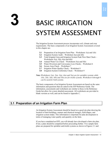
CREATING A WATERING SCHEDULE .For most consumers, it is much easier to plan your specific wateringschedule onto paper before actually programming the informationinto the controller. It’s also handy to have a written record of yourprogramming information for easy reference.There are some guidelines that should be followed when determiningwhen and how long to water. These factors are the soil type, the partof the landscape being watered, weather conditions, and the types ofsprinklers being used. Since there are so many different variables thatcan determine your individual watering schedule, it is impossible to givean exact schedule to follow. However, we have included some guidelinesto help you get started.NOTE: It is usually good to water one or two hoursbefore sunrise. Water pressure will be at optimumlevels during the early morning and the water cansoak into the roots of the plants while evaporation isminimal. For most plants, watering during midday orin the evening may cause plant damage or possibly mildew.NOTE: Keep an eye out for evidence of under- or overwatering. Over-watering is most commonly indicatedby pools of water that take a long time to soak inor evaporate, while under-watered landscapeswill show signs of discoloring and dryness. Makeprogramming changes immediately when evidenceis present.HOW TO FILL OUT THE WATERING SCHEDULE FORM .Be sure to use a pencil when filling out this form. By using the includedexample and the information below, you should have all the informationyou need to construct your personal water schedule.Program Start Times – Indicate the time of day that the program willbegin. Each program can have 1 to 4 start times. However, one start timecan run an entire program.Station Number and Location – Identify the station number, locationand the type of plant that is being watered.Station Run Time – Indicate the run time (1 to 99 minutes) for eachstation. Write “OFF” for any station that you do not want to operate inthe program.Watering Day – Identify whether you want to use a calendar day or anodd or even day schedule. For a calendar day schedule circle the day ofthe week in which watering is desired. For a odd or even day schedule,simply mark the corresponding box.12Keep this schedule in a safe place for quick reference later, rather thanscrolling through program information on the controller.
WATERING SCHEDULE FORM EXAMPLE .PROGRAM AWATERINGDAYSCHEDULECALENDARODD/EVENPROGRAM BPROGRAM CSU MO TU WE TH FR SA SU MO TU WE TH FR SA SU MO TU WE TH FR SAODD XEVENX X X X X X XODDEVENODDEVEN XSTATIONLOCATIONZONE RUN TIMEZONE RUN TIMEZONE RUN TIME1Front LawnSide LawnBack LawnFlowersGardenFront 000:1500:0000:0000:0000:0000:0000:0000:2001:006:00 AMOffOffOff8:00 AMOffOffOff5:00 AMOffOffOff234567891PROGRAMSTART TIMES23413
WATERING SCHEDULE FORM.PROGRAM N234567891PROGRAMSTART TIMES23414PROGRAM CSU MO TU WE TH FR SA SU MO TU WE TH FR SA SU MO TU WE TH FR SAODDEVENZONE RUN TIME1PROGRAM BODDEVENZONE RUN TIMEODDEVENZONE RUN TIME
PROGRAMMING FUNDAMENTALS .A watering program can be created to operate valves in numericalsequence one at a time. All that is required to create a watering programis to:1. Select a program (A, B, or C) by pressing the button on thecontroller (it is recommended to start with Program A).2. Set a program start time (only one program start time is required toactivate a watering program).3. Set the run time for each valve assigned to the program, and4. Set the days that you would like the watering program to run.We have included an example that will better illustrate the operationof a program:Let’s say you have a program start time set for 6:00 AM . Stations 1 and2 are going to have a run time of 15 minutes and station 3 is set for 20minutes. Please note that stations 4, 5 and 6 have not been included inthis program, we will water them on separate programs.Going back to our previous example, at 6:00 AM the controller
SRC Plus is a product that does the job efficiently and economically. The SRC Plus is an improved version of the original SRC Plus. Additional features and improvements include: Non-volatile memory More robust circuitry One touch manual start and advance Hunter Quick Check Automatic Short Circuit Protection