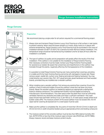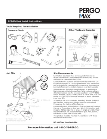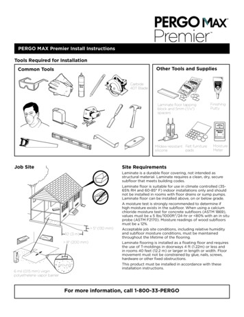
Transcription
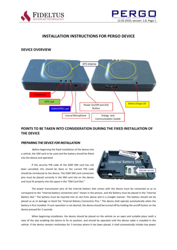
12.02.2010, version: 1.8, Page 1INSTALLATION INSTRUCTIONS FOR PERGO DEVICEDEVICE OVERVIEWPOINTS TO BE TAKEN INTO CONSIDERATION DURING THE FIXED INSTALLATION OFTHE DEVICEPREPARING THE DEVICE FOR INSTALLATIONBefore beginning the fixed installation of the device intoa vehicle, the SIM card to be used and the battery should be fittedinto the device and operated.If the security PIN code of the GSM SIM card has notbeen cancelled, this should be done or the current PIN codeshould be introduced to the device. The GSM SIM card connectionpins must be placed correctly in the SIM card slot on the deviceand must fit properly into the space in the “SIM Card Slot.”The power transmission pins of the internal battery that comes with the device must be connected so as tocorrespond to the “Internal battery connection pins” shown in the picture, and the Battery must be placed in the “InternalBattery Slot.” The battery must be inserted into its slot from above and in a straight manner. The battery should not beplaced so as to damage or bend the “Internal Battery Connection Pins.” The device shall operate automatically when thebattery is first installed. If such operation is not desired, the device should be turned off by holding the on/off button on thedevice pressed for 2 seconds.When beginning installation, the device should be placed on the vehicle on an open and suitable place (with aview of the sky) enabling the device to fix its position, and should be operated until the device cable is installed in thevehicle. If the device remains motionless for 3 minutes where it has been placed, it shall automatically initiate low power
12.02.2010, version: 1.8, Page 2consumption mode and shall shut itself down. After being turned on, the device must be checked at a time close to theautomatic shut-down time, and whether only the red led blinks once every two seconds MUST be checked. Otherwise theinstallation must be discontinued. If the green and blue lit leds do not go out in more than one device, the reason for suchfailure must be examined. Warning: The green lit led shall not go out if you are in a closed environment.The continuous lighting of one or more of the series of 3 leds (red, green, blue) indicates a malfunction, and insuch cases the device must NEVER be installed.The yellow led on the connector end of the device indicates the charge status of the battery. This led shall notlight up as long as external power is not supplied to the device. If this led blinks rapidly when external energy is supplied tothe device, this means that there is no battery in the device or that the battery in the device is not in contact with the“Internal Battery Connection Pins.” This must be corrected. If the yellow led continues blinking although the battery hasbeen placed, the installation must be discontinued. The yellow led must light up continuously when external power isattached to the device. This shows that the battery in the device is being recharged. The yellow led shall go out when therecharging of the Internal Battery has been completed.DETERMINING A SUITABLE PLACE FOR INSTALLATION IN THE VEHICLEThe correct operation of the installed device depends entirelyon the place of installation. To ensure that the GPS modulewithin the device is able to obtain a location fix, the devicemust be installed making sure that the logo on the device boxin the shape of a satellite dish faces skywards.There must be no metal surfaces over the place where thedevice is to be fixed. If possible, the device must be fixed to aplace under the front panel of the vehicle, which is indicated inthe picture as area no. 1. In the event that there are no suitableplaces for installation within area no. 1, installation can bemade in areas no. 3. The device must under no circumstancesbe installed sideways or upside down, and must be securedfirmly. The excess of the vehicle connection cable used in theinstallation of the device must not be stored close to the device. Care must be taken to prevent the connection cable frompulling and forcing the device's socket. The device MUST NOT BE FIXED in a manner allowing the device to become looseand detach due to the vibration in the vehicle. The installation must not be performed in a manner that allows the sides orupper surface of the device socket to come into contact with surfaces. Otherwise, the vibrations in the vehicle will damagethe socket and may cause the continuous generation of power cut/power on messages.0The device must be operated within a temperature range of -20 ile 60 C since it contains a li-ion battery. For this reason,the location chosen for installation must not be adjacent to the vehicle’s heating system.The installed device must be parallel to the vehicle. Figure 1 at the left indicates thecorrect installation. The installation positions in the second figure are incorrect.Installations as pictured in the second figure may cause the generation of wrong resultswhile reporting changes in heading (straight, sideways or reverse operation) and accidentsto the centre.ISSUES TO BE TAKEN INTO CONSIDERATION DURING CABLE INSTALLATION
12.02.2010, version: 1.8, Page 3In order to perform the fixed installation ofthe device to the vehicle, it is necessarythat at least 3 cables in the bunch of cablesproduced for the device should beconnectedtovehiclepower.Duringassembly, the cable ends belonging to thedevice must under no circumstances beattached between the fuse legs on thevehicle fuse board. The device cable endsmust NEVER be attached to anywherebetween the vehicle battery and the fuseboard. In such an installation, as there shallbe no hardware to act as fuse between thepower from the vehicle battery and thecable leading to the Pergo device, any shortcircuit that may occur in the device cable orthe vehicle cable may cause damage in the vehicle. Therefore, the cables of the Pergo device must be connected to a cablein a suitable place after passing the fuse panel of the vehicle. The cables should be connected with extreme care. The cablesshould not be left bare in a manner allowing short circuit and, if necessary, specifically produced cable connectors withprotection should be used for connecting cables.During the installation of the device cable, it is especially important to receive the post-contact powered cable from thecorrect position. While determining the post-contact powered cable, only the ignition switch should be turned on and noother hardware should be working in the vehicle (radio, heating, air conditioning, lamps etc.). For instance, receiving thepost-contact power not from the real post-contact power but from the power cable leading to the air conditioning whilethe air conditioning is working will cause the device to generate an ignition switch-off and power-off alarm when the aircondition is turned off while the vehicle is running.Pergo device cables, the installations of which are necessary;Red: Must be connected to the cable that has uninterrupted power whilethe vehicle is running or stopping. The device must be supplied withuninterrupted power whether or not the ignition switch of the vehicle isturned on.Socket edge cutSocket edge not cutBlue: Grounding; the grounding connection should be made in thecorrect place.White: Must be connected to the cable that is powered only when the vehicle has been started (ignition switch turned on).Green: If the panic button is to be used, it must be installed. Of the two cables leading from the panic button, one should beconnected to the device’s green cable and the other to the continuously powered vehicle cable to which the red cable ofthe device has been connected. It can also be connected to the Red cable of the device. This cable must under nocircumstances be connected to a place that does not have power while the ignition switch of the vehicle is turned off.Otherwise the panic button shall not work when the ignition switch is turned off.ATTENTION. On one end of the cable to be used in performing the fixed installation of the device to the vehicle, there is asocket compatible with the Pergo device in order to enable connection with the Pergo device. In order that this socket iseasily connected to the corresponding socket on the vehicle, the plastic pieces at the edges of the end should be cut with asuitable cutter if they are not already removed. If these are not cut and if you intend to cut them with tools such as a utility
12.02.2010, version: 1.8, Page 4knife, please take care not to get injured and do not force the socket of the device, cutting/breaking the socket completely.Please check whether or not the cable socket is fully connected to the socket in the Pergo device. The socket must under nocircumstances be forced into place. The device must not be installed if the socket does not fit into place easily.CONNECTING THE DEVICE TO THE VEHICLE CONNECTION CABLE, STARTING THE DEVICE ANDTESTING THE CONNECTIONSThe device is connected to the vehicle connection cable while the vehicle ignition switch is turned on and the device is shutdown using the button. The device is turned on using the on/off button. When a mobile-operating device is supplied withignition switch power, the device will shift to automatic switch operation mode. When shifting from mobile to ignitionswitch operation the device will reset itself and from then on start according to the ignition switch operation mode uponstart-up. In order to switch a device operating in the ignition switch mode to the mobile mode again, the battery of thedevice must be removed in the absence of external cable connection and the internal battery must be installed whilepressing the on/off button. The on-off button must be held pressed for 10 seconds. When the on/off button is released, thedevice will start mobile operation.When the power of a device (removed from the vehicle), which has been set to external power mode operation, has beencut (when the vehicle connection cable is disconnected), the device will turn of all of its lamps and will not respond toattempts to turn it on or off using the button. In order that such device may operate in mobile mode again, the battery inthe device must be removed and reinstalled. As the device will be operating on mobile mode after this procedure, it willrespond to requests of turning on/off by using the button.The device operating on power mode can be used to perform checks such as whether or not the external cable connectionsare made correctly.Testing the External Connection Socket1.The device is operated. (By installing the battery or holding the on/off button pressed for 2 sec.)2.The vehicle ignition switch is turned off.3.The socket on the vehicle connection cable is connected to the socket on the device. The yellow led will go on andstay lit at the end of this procedure. If the yellow led blinks with short intervals or does not light at all the devicemust not be installed or the problem must be solved.4.The vehicle ignition switch is turned on.5.When the device senses the ignition switch power from its external power cable it shall reset itself automaticallyand reboot. This procedure will last about 15-30 seconds. If resetting has not occurred, the cable test cannot beperformed and the device will shut down when the on/off button is pressed for testing, since the device shall beon mobile mode. In such case the ignition switch connection should be checked. If you are sure of the correctnessof the ignition switch connection, there might be a problem in the socket connection of the device; under suchcircumstances the device must not be installed.6. In order to test whether or not the cable connections are correct, a cable test must be performed according to thestatuses of the on/off button and the series of 3 illuminated leds on the device. Accordingly;a.The on/off button on the device is held pressed. (Warning: If the device turns off after 2 seconds, theignition switch connection may not have been recognised by the device/the ignition switch connectionmay be defective/the device may be defective. These three different conditions must be rechecked.)
12.02.2010, version: 1.8, Page 5b.If the external power connection is correct, the green illuminated led in the centre shall lightcontinuously.c.The blue illuminated led will light continuously because the vehicle ignition switch is on.d.If the Panic button is pressed, the red illuminated led will light continuously. The red illuminated ledwill go off when the Panic button is released.e.The vehicle ignition switch is turned off.f.Whether or not the blue illuminated led has gone off is checked. If it does not, the vehicle ignitionswitch connection cable must be controlled.g.Whether or not the green illuminated led at the centre continues to light is checked. If it does not, thevehicle battery power connection connected to the red cable should be checked.h.The Panic button is pressed again, the red illuminated led must light continuously. The red illuminatedled will go off when the Panic button is released.i.If all the above tests have been conducted and the correct led statuses have been observed, the on/offbutton of the device is released.j.The vehicle ignition switch is turned on again. The red and blue illuminated leds on the device shallstart lighting after approximately 0-30 seconds. The green illuminated led will possibly not light. Thisindicates that the device has performed the location fix.k.The device is fixed to its place in the vehicle firmly, without causing its socket to be cramped.l.Whether or not only the red illuminated led on the device is blinking is checked. (The yellowilluminated led on the far side of the series of three leds will light continuously. This indicates that thebattery is being recharged. The other green and blue illuminated leds must be off.m. The vehicle ignition switch is turned off. Approximately 30 seconds later, none of the 3 leds on thedevice must be lit.n. The installation form for the vehicle is completed and forwarded to the call centre.
12.02.2010, version: 1.8, Page 6TROUBLESHOOTING1. Blue (GSM/GPRS) illuminated led statusa. If the blue led is continuously on;i.A SIM card may not be inserted.ii.The SIM card PIN code inquiry may not have been cancelled and may not have beenrecognised by the device.iii.The GSM Modem may be defective.In order to understand the exact reason of the problem, the device must be connected to thecomputer and checked.2. Yellow (GPS) illuminated led statusa.If the yellow led is on continuously, the GPS is defective and the installation must not beperformed.b.If the yellow led continues blinking at 2 sec. intervals for more than 3 minutes this means that ithas not succeeded in fixing the position. The reasons for this may be;i.The GPS of the device may be defective.ii.The device may be situated in a closed area, between high buildings or right next to abuilding wall. Under such circumstances the position fix may take time or may not beachieved at all.3. The device shuts down automatically 30 sec. after start-up. All leds go off.i.If the battery level of the device is below 20%, the device may be shutting down due tolow battery.ii.The device may be shutting down because its IMEI number is not recognised by theserver to which the device tries to connect. (This condition is not valid for a taxi server. Adevice set to connect to a taxi server will be recognised automatically by the system evenif it has not been designated, and connection shall be allowed.
places for installation within area no. 1, installation can be made in areas no. 3. The device must under no circumstances be installed sideways or upside down, and must be secured firmly. The excess of the vehicle connection cable used in the installation of the device must not be stored close to the device.