Transcription
WHAT’S NEW IN BOBCAMFOR SOLIDWORKS V10INTRODUCTIONThe new BobCAM for SOLIDWORKS V10 has a ton of new features and even enhancements to existingfeatures! With the introduction of our Wire EDM module, we’re finally able to welcome our wire-friendsto the BobCAM family. Craft your art projects more easily with the redefined workflow of the all newBobART user interface! For those requesting more control of the operation posting order, includinghow toolpath patterns are posted, we decided to completely rethink this portion of the software andare introducing the new Operation Tree and Tool Tree to give you all the power and control you need.Oh, and we’ve got Finishing Spring Passes, brand new Leads with point picking and automatic leadfrom center options, and new features and enhancements in 2, 3, 4, and 5 Axis. Whether you’re a newcustomer, or already part of the family, this version is going to make you glad you’re here!NEW FEATURESBOBARTBobART has received a long overdue workflow overhaul to help you get the results you’re looking forwithout the hassle! When vectorizing images in the past, the Raster to Vector dialog was a floatingwindow with a static image to give you an idea of the detail you were pulling from the image to createthe geometry with. This method had its downsides as you could not adjust your view of the image beingused. In this latest release the Vectorize dialog is opened directly in the Data Entry Manager whichallows you to view the image in the graphics area as you normally would. Zoom in, Pan, and even Rotateto put as much focus on the area whichever areas interest you the most!1
Since previous versions did not allow you to zoom in on the image, vectorization may need to be doneseveral times to get the desired results. In those circumstances you’d need to right-click the image andselect Vectorize again to reopen the dialog, adjust results and click OK again to double check the resultsonce more. In this version we did away with the tiresome back and forth and allow you to instantlyreview your results before you ever exit the Vectorize dialog. Simply click Apply, Blank the image, checkyour results in the graphics area and adjust as needed. Once you get the results you need, click OK andyou’re done.With the new and improved BobART dialogs you can regenerate the canvas without exiting! In the past,creating emboss features consisted of selecting the feature, setting the parameters, exiting the dialogto add geometry to each of the applicable feature items in the BobART Tree, and then regeneratingto view the result. This could be a little frustrating, especially if you needed to adjust the selectedgeometry and the parameters. Now, you deal with a single dialog and can make sure you’re happy withthe result before you ever exit!2
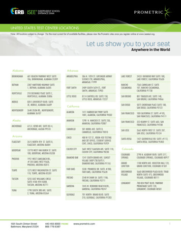
To improve an already amazing workflow, we’ve added automatic regeneration! Once you think youthink you have the parameters where you ‘d like them, click Apply to update the canvas. Now, anytimeyou add geometry, the canvas is regenerated with the new geometry and with whatever parametersyou may have adjusted in the meantime!Oh, and did we mention we now have a “Make as Solid” option? In the past, while you could do thingsto give a height to your model, extended walls were really the only thing added. You were still left withwhat was essentially a mesh surface draped down to the floor. Looking behind the model, as seen inthe first image, it was apparent the mesh was not closed. With this new option, as you can see in thefollowing image, the mesh is closed creating a water-tight mesh. This expands the possibilities of whatcan be done with your final model, and we’ve even added unit options allowing you to specify the unitsto use when exporting STL Components!3
CAMGENERALOPERATION TREEThe Operation Tree is now your go-to place for all your posting needs! We’ve always beena feature-based CAM system, and this meant the order of your machining operations didn’talways correlate to the order you’ve created them in the CAM Tree. In previous versions,this was managed in the Machining Order dialog which allowed you to sort the operationposting order. In this latest release the Machining order dialog has been replaced by acomplete Operation Tree which enhances the workflow in the software in many ways thatwere never possible: See all jobs and their operations regardless oftheir posting statusIn the past operations that we set to not post were notshown in the Machining Order dialog. This could causeconfusion about their posted position once their postingstatus was reinstated. With the Operation Tree, you seeall operations and their current posting status. Edit OperationsWhile reviewing your operations in the Operation Treeyou might notice something you’d like to update in thetoolpath. With the new Operation Tree, you can simplyright-click the operation and select Edit to launch thewizard! Adjust anything you need and click Compute! Post Yes/No flags can be seen and managedNot only can you see which operations are set to postand which are not, you can also control these statesdirectly in the Operation Tree. By selecting multipleoperations, you can even update the state of severaloperations at once! Multi-select functionalityUse the standard Ctrl/Shift keyboard modifiers to selectmultiple operations at once. Once selected you canupdate their posting status simultaneously, drag anddrop to update their order, simulate them, and evenpost them!4
Manage patterned operationsIn the past the Machining Order dialog did not display, let alone allow you to manage, the individualpatterned instances of an operation. If the pattern is set to post in the CAM Tree, the OperationTree will allow you to update their individual posting state, adjust their posting, simulate them, andpost them! Show or hide all patterned operationsThe toolpath patterns can easily be hidden and shown with the Toolpath Pattern Options in theQuick Access menu of the Operation Tree. Control whether hidden patterns should be postedWhen deciding to hide patterned operations we provide an additional option which allows you todetermine whether the hidden operations should be posted. New toolpath pattern sorting optionsAlong with the check box to adjust their visibility are the options to automatically adjust theirposting order with the Operation Priority and Feature Priority buttons. Posting Order Violation warningThe new Operation Tree gives you complete control of the posting order, even allowing you toviolate the usual posting rules preventing finishing operations from posting before their associatedroughing operations. When moving operations in the operation tree, you’ll automatically beprevented from moving your finish before its rough unless its set not to post. Once reordered, andset to post, warning icons ( ) will be shown to alert you to the violation and attempting to post willshow you a warning message to alert you to the issue once more. But we assume you know whatyou’re doing, so just click *Yes and we’ll post it just the way you have it.*BobCAD-CAM and it associated partners bear no responsibility for any broken tools, or exploded machines. Simulate entire jobs, groups of operations, or individual operationsSimulating what you need has never been easier. In the past, simulating a single operation, or acouple operations meant everything else had to be set to Post No. Now, simply select what youwant and choose Simulate Selected! Create setup sheets for entire jobs, groups of operations, or individual operationsJust like you can create setup sheets in the CAM Tree, you can also create setup sheet in theOperation Tree! Unlike the CAM Tree though, you don’t need to go through each operation youdon’t want in the setup sheet and change its posting state to Post No. Just highlight the operationsyou want on the setup sheet along with the job, right-click and choose Generate SelectedSetup Sheet! Post entire jobs, groups of operations, or individual operationsThe Operation Tree allows you to easily post exactly what you need directly! Right-click a job andselect Post to post everything. Select a single operation, or even multiple operations at once, rightclick and Post.5
TOOL TREEThe Tool Tree is your one-stop shop for everything tool related. Once you’vecreated your jobs in the CAM Tree, open the Tool Tree to see all your jobs,the tools in their tool crib, and which operations are assigned to each tool! Access the Tool CribsWith all your jobs available, simply highlight part of that joband click the Tool Crib button in the quick access menu toopen the Tool Crib dialog and view all the tools in the job. Access the Tool LibraryClick the Tool Library button in the quick access menu toopen the Tool Library and view available tools, add tools,or edit existing tools with ease. Post all operations for a toolIn some cases, you may want to post the operations whichare utilizing a particular tool. This has never been easierwith the Tool Tree! Simply right-click the tool, select Postthis Tool’s Operation(s), and all operations under that toolare posted instantly. Updating toolsDid something change and now you need to update thetool being used in several operations? No problem! Simplyright-click the tool and select Replace. You’ll then bepresented with a message telling you it’s in use and asksif you want to change the tool in all operations that use it.Click Yes, and the Tool Library launches, allowing you to pick your replacement. Pick the new tool,click OK and your tool is updated. Now right-click the new tool and select Compute All Toolpath. Compute All ToolpathWhen you update tools, operations which utilize that tool need to be recomputed. In the past thiscould be annoying since you would need to find the operations that use that tool and recomputethem. And in previous version, no identifiers were placed on the operations in the CAM Tree tohelp you identify which operations needed to be recomputed for the new tool parameters. Withthe Tool Tree, all operations which need to be recomputed are identified with a warning icon.Plus, the operations are marked everywhere they are visible, in the CAM Tree, in the OperationTree, and of course in the Tool Tree! Now, simply right-click the new tool and select Compute AllToolpath. All the operations under this tool are computed with the new tool parameters!6
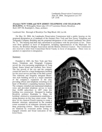
Edit OperationsWhile reviewing your operations in the Tool Tree you might notice something you’d like to updatein the toolpath. With the new Tool Tree, you can simply right-click the operation and select Edit tolaunch the wizard! Adjust anything you need and click Compute! Move OperationsIn some cases you may notice an operation under the tool which should be utilizing a differenttool. Right-click the operation and select Move To and the Tool Selection dialog launches todisplay all the tools in your Tool Crib. Select the proper tool and select OK. You can even justdrag the operations to the tool you’d like it to utilize! That operation will now show under thenewly selected tool with an icon showing it needs to be recomputed. Right-click, select ComputeToolpath, and you’re done!MDIFor the first time ever, Mill and Lathe jobs also support MDI, or manual data input, which allows you tomanually define machine movement as needed for your machining operations. MDI allows you to buildlines of code by deciding where to add the new lines, and what commands should be in those lines.In the image below, you can see we have added a dwell after the operation, and raised the Z axis ata specified speed before rapiding to X0,Y0. These task lists can customized however you need them,saved, and reloaded to any operation necessary, giving you the control you need to get the resultsyou want!7
MILLMILL EXPRESSNEW LEADSPointThe new Point lead allows you to select a user defined point, orpoints from the graphics area to define the start and end pointsof the toolpath. In the past users have been able to add straightleads with the parallel and Right Angle lead options, but besidesbeing able to set the chain start point and the length of thoseleads, there has not been a way to select a particular locationfor the start and end that isn’t in line with those constraints. Inthis latest release, simply select Point and select Pick Points tolaunch the Lead-in/out Points dialog. Set your points, click OKand you’re done.Point BlendThe new Point Blend lead allows you to select a user definedpoint, or points from the graphics area to define the start andend points of the toolpath. In the past users have been ableto add leads which arc into the toolpath with the Circular andBlend lead options, but besides being able to set the chain startpoint and the length of those leads, there has not been a way toselect a particular location for the start and end that isn’t in linewith those constraints. In this latest release, simply select PointBlend and select Pick Points to launch the Lead-in/out Pointsdialog. Set your points, click OK and you’re done.8
Lead from CenterBy default the Lead from Center option allows you to utilize the center most positions of the createdtoolpath chains. In the past creating leads that started/ended in the center of the chain could be a littlemore challenging than you’d initially think. In fact, customers requesting the ability to do this easily iswhat lead to these new lead types! So here you go! Lead from Center made easy! No need to measureareas and calculate leads.These leads work on any shape to find the center-most point created by the chains!9
The Lead-in/out Points DialogThe new dialog allows you to select points toassign to the toolpath chains. Automatic Mapping - automatically assignspoints to the chains. One to One Mapping - prevents multiplechains from using the same point. One to Multiple Mapping - allowsmultiple chains to use the same point. Add Center Points - assigns each insidechain a center point. Map - This area lists all selected points andchains and allows manual control: Drag points to the intended chain Move points with the up/down buttons Delete points from their currentlyassigned chains Delete points from the SelectedGeometry list Add Center Points to chainsSPRING PASSESFor the first time ever, this latest release offers a Spring Passes option to make finishing easier than ever!Usually when finishing vertical walls, spring passes are applied to ensure tool deflection and chatterhaven’t had a negative impact on the result. In the past, this meant needing to apply a couple extraoperations to the feature to behave as the spring passes. Now, this can all be done automatically in thesame operation with a simple check box. Simply select Spring Passes, set the Number of Passes, anddecide whether to apply the spring passes to all depth cuts and whether the leads should be applied10
prior to these spring pass. The operation will then automatically make those additional passes at the finalprofile to give you the spring passes you need! Spring Passes are available for the following operations: Profile RoughProfile FinishChamfer MillCorner RoundingTwo Additional Operations(old method)Apply Leads Prior to Spring PassApply Leads Prior to Spring PassFull retract to clearance each passRetract to clearance each passNo retract between passesMINIMIZE LINKSThe new Minimize Links option has been added to the Advanced Pocket’s Offset Out and Morph Spiralpatterns. This new option does extra processing on the toolpath to adjust the start points of the toolpathand attempt to use parts of the actual toolpath for linking instead of retracting and repositioning. Theaim here is to reduce the amount of time the tool spends in the air and keep it engaged in the materialmaking profits!Minimize LinksMinimize Links11
MILL 3 AXIS STANDARDRAMP AT DRILL POSITIONSWhen utilizing the Adaptive pattern of the Mill 2 Axis Pocket operation, many users have begun torealize how they can control the shape of the toolpath by adjusting the start locations with the Drill TipPositions. The downside to using Drill Tip Positions is that the software assumes there is a drilled holeat these positions, so the tool would always plunge. To give the users the control to adjust the startlocations when using the Drill Tip Position points, we have added a Ramp at Drill Positions checkbox sothat ramping at this position is now possible! This is only available for the Adaptive pattern.When using an advanced pocket with a ramp entry, you maywant to enter from previously drilled positions in the stock.In the past, selecting drill tip positions overrode the ramp entrymethod and applied a basic plunge entry.By selecting Ramp at Drill Positions, you can easily ensure aramp is still applied to the selected drill tip positions!12
SMOOTHINGThe same powerful smoothing options which have been available for our Advanced Roughing operationare now available for the Offset Pocket Out and Offset Pocket In patterns of the Advanced Pocket!Clicking on the Smoothing button in the Parameters page will launch the Smoothing dialog, allowing youaccess to. Smooth Corners - to create fillets in the sharp corners of the toolpath. Smooth Links - to smooth the links within a group. Smooth Final Contour - to create fillets in the sharp corners of outer contours. Ignore Small Contour - box to remove small pockets and segments which are notnecessary to machine. Remove Corner Pegs - to add extra tool movement in corners, removing the rest material with: Line-Arc-Line - removes the corner pegs with an arc between two lines. Arc - removes the corner pegs with a single looping arc motion. Line - removes the corner pegs by moving away from, and back to the toolpath with astraight line.13
USE LEAD-OUTThe Advanced Pocket now provides control over the Lead-Out option in the Leads page for all patternsbut the Adaptive Roughing. Normally, when a wall was encountered on the last pass of the pattern, a leadout was automatically applied. While this lead-out worked great in most cases, users have requested tohave some control over the lead-out. In this version we now provide the controls to customize the sizeof this lead-out, or even to shut it off completely!Lead-out OffLead-out OnLead-out sizeMILL 3 AXIS PROINDEPENDENT CUTTING METHODSThe powerful Steep Shallow operation has gotten even more powerful with the ability to control theCut Direction for the Steep and Shallow aspects of the operation independently. The Steep Shallowoperation is arguably the most versatile operation in the ‘toolbox’, but until now, could only be controlledby a single cut direction: Zig with Climb or Conventional milling, or a Zig Zag. This choice would apply tothe overall toolpath on both the steep, and shallow areas. Now, by selecting the Independent Methodscheck box in the Patterns page, you can assign one direction for the steep areas and one for the shallowareas, making one of the most versatile toolpaths even more versatile.14
SPIRAL PITCH CONTROLNew controls in the Parameters page of the Advanced Z Level Finish allow you to set an angle to theSpiral method rather than just a depth of cut. Applying the Spiral method to the Advanced Z LevelFinish has always been a great way to eliminate linking moves to get the best possible finish. In the pastthough, the only way to specify how tight of a spiral to use was by setting the Depth of Cut. Now, byselecting Spiral Angle in the Depth of Cut group, you can specify an Angle and a Maximum Depth to use,giving you just a little more control when perfecting your toolpath!Define the AngleSet a Maximum DepthNote: The Maximum Depth ensures a full cut at each Maximum Depth increment. In the images above, the first is given amaximum depth greater than the part depth, while the second is given a maximum depth of half the part depth.15
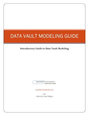
DYNAMIC HOLDER CHECKINGThe power of Dynamic Holder Checking has now been extended to many of the finishing operations! Whenusing a short tool, it can be impossible to get to the necessary depth without causing a collision betweenthe machining surface and the holder. In the past, you could use gouge checking options which check forgouges once the toolpath has been calculated, and then trim and relink the toolpath. Now, this option checksfor gouges in the machining surface during the toolpath calculation and offsets the toolpath as necessary! Advanced Z Level FinishAdvanced PlanarEquidistantProject CurvesFlatlandsPencilOriginal toolpathGouge Check: RetractDynamic Holder CheckingCollision Safe Area Only16
START LOCATION CONTROLThis latest version brings the power of start location selection to the Advanced Rough, Equidistant, andPencil operations. When programming a part, the more control you have, the better. That’s why it wassuch a huge hit when we offered control over exactly where your Advanced Z Level operations starts.Now this same control is available in these other operations! Simply select your start point from thegraphics area, or even enter it manually!Undesirable Start LocationAdjusted Start LocationThis works for the regions as well! Whereas the above example has only one start point, operationswith multiple regions have multiple start points as in the examples below. Notice the original part withtoolpath and notice the start points being affected with the selected start points.17
STOCK HAS UNDERCUTSThe Advanced Rough operation now has the Stock Has Undercuts option to allow you to ignore areasin the stock that are undercut. One of the main advantages of the Advanced Rough has always been itsability to focus only on the stock and avoid air cutting when the top of the stock is not flat. In the pastthough, the operation did not have the ability to recognize undercut areas of the stock. This meant evena small lip at the top of a stock form would cause toolpath to continue down past the lip and waste timecutting air. This new option allows these areas to be recognized and ignored, saving more time thanever before possible, and even offers an Axial Shift option to control how much is trimmed!Stock Has UndercutsStock Has UndercutsStock Has Undercuts Axial ShiftCORNER SLOWDOWNThe Equidistant operation now allows you to slow the feedrate when moving into corners. Whenprogramming speeds and feeds many things need to be taken into consideration, especially ensuringthe tool does not engage too much material at the same time since this can easily break a tool. Whenmoving around a part, additional stock is always encountered in the corners, so a corner slowdownoption has always been a hugely popular customer request. When we brought that power to manyof our Mill 2 Axis features it was an enormous hit! Now, we offer that same control in one of the mostpowerful 3 Axis operations ever: The Equidistant operation!18
RAMP AT DRILL POSITIONSWhen utilizing the Adaptive pattern of the Mill 3 Axis Advanced Rough operation, many users havebegun to realize how they can control the shape of the toolpath by adjusting the start locations with theDrill Tip Positions. The downside to using Drill Tip Positions is that the software assumes there is a drilledhole at these positions, so the tool would always plunge. To give the users the control to adjust the startlocations when using the Drill Tip Position points, we have added a Ramp at Drill Positions checkbox sothat ramping at this position is now possible! This is only available for the Adaptive pattern.When using an advanced pocket with a ramp entry, you maywant to enter from previously drilled positions in the stock.In the past, selecting drill tip positions overrode the ramp entrymethod and applied a basic plunge entry.By selecting Ramp at Drill Positions, you can easily ensure aramp is still applied to the selected drill tip positions!19
RETRACT CLEARANCE FOR 3-AXIS UNDERCUTSA new feature has been added to the Advanced Z Level Finish allowing you to do undercuts with a radialclearance added for the tool. When using tools like a t-cutter to preform undercuts, making sure thetool doesn’t contact the part when entering and exiting the cuts is extremely important. In this version,simply add a Retract Clearance value in the Options page to provide additional clearance as necessary.No Retract ClearanceRetract ClearanceMILL 3 AXIS PREMIUMDEBURRINGChamfer ToolLast year we introduced the new Deburring toolpathwhich supported fully automated deburringprocesses for 3, 4, and 5 axis machining by practicallyjust selecting the model and hitting compute. In theinitial release, only spherical tools could be used,such as ball end mills, lollipops, and tapered ball endmills. Of course, the biggest request was making itwork with Chamfer tools, and now in this releaseyou absolutely can! Endmill RoughEndmill FinishTaperedLollipopChamfer Mill20
CONTAINMENT BODYNow you can automatically specify which areas to deburr by selecting a containment body! While theDeburring operation has always offered ways to specify the area to focus on by allowing selection ofspecific edges, check surfaces to avoid, and limiting the area by height, deburring only specific areasmeant a lot of geometry selections and even adjustment of the operation settings. Now, hitting exactlywhat needs to be hit has never been easier. Simply select a solid, or solids from the graphics area andonly the area inside of these solids will have the Deburring toolpath applied!Before 3D ContainmentAdding 3D ContainmentAfter 3D ContainmentALLOW ASYMMETRIC CHAMFERA new option has been added to the Advanced auto edge detection dialog of the Deburring operationto allow you to cut asymmetric chamfers when using the fixed tool contact point option in a 3 or 4 Axissetup. Symmetric chamfer geometry is defined by half the edge angle, and in the past edge anglesbeyond this range were ignored. By allowing asymmetric chamfers you’re able to machine more edgeswith different angles and orientations to hit more edges automatically than ever before.Allow Asymmetric ChamferAllow Asymmetric Chamfer21
FIXED TOOL CONTACT POINT ON CONE / CYLINDERThe new Fixed tool contact point on cone/cylinder option enables you to specify where the edges shouldcontact the cutting edge of the tool. In previous versions fixed contact point options were not availablefor the deburring operation. With option you can determine exactly where the tool is positioned with afixed contact point as specified with a value of 0 to set it as the lowest point, up to a value of 1 to set itat the highest point of the cone/cylinder. This option allows you to create an incredibly uniform chamferbut do note to create a uniform chamfer the tool is not tilted, and toolpath will be trimmed instead oftilted to avoid areas of collision.SPIRALIZE CLOSED CONTOURSWhen using multiple cuts along edges, the new Spiralize closed contours option allows you to spiralto the additional cuts instead of using linking moves. In some cases, multiple cuts need to be appliedto edges, and in the past those separate cuts were connected by linking moves which can result invisible marks on the final product. To eliminate this issue, the new Spiralize closed contours uses a spiralmove along the contour to smooth the transition into the next cut. This helps create smoother machinemovements and a cleaner result!Spiralize closed contoursSpiralize closed contours22
FLOW DIRECTIONNew options have been added to the Flow directions of the Flowline toolpath which allow you to choosebetween U - direction and V - direction. In the past, the only Flow directions available were Long sideand Short side, which were the same directions, but selectable only by which was longer/shorter. Insome cases, users wanted the U or V direction to have priority regardless of its length. In that scenariothe only option was choosing one and seeing if that was the desired result. With these new options,you have everything you need to specify either the U or V direction regardless of length, or lengthregardless of direction.U - directionV - directionMILL 4 AXIS STANDARDMAXIMUM/EXACT ANGLE STEPNew options in the Links page of the 4 Axis Rotary operation allow you to set a maximum angle step forthe rapid moves of the operation. While the 4 Axis Rotary toolpath has always had options to controlthe links of the toolpath, control of the rapids, besides the height of those rapids, has not been available.With this latest version, you can specify an angle step which can be treated as a maximum angle withthe rapids divided into equal parts or used an exact value.U - directionV - direction23
MILL 4 AXIS PROCONICAL MACHININGA brand-new option has been added to the 4 AxisAdvanced Rough and 4 Axis Advanced Finishoperations which perfectly applies the toolpath toconical shapes! Conical machining can be tricky, andwhen we came out with our 4 Axis Advanced Roughand 4 Axis Advanced Finish operations it helped a lotin the machining of those shapes, but the toolpathwasn’t specialized for those shapes, and there werestill some drawbacks. Everything from the stepdowns to the limits, is designed for cylindrical shapes.That meant conical floors would have steps, and aircutting on the smaller end was impossible to removewith radial limits. These issues are now a thing of thepast with the new Conical Machining option. Simplyselect the check box on the Patterns page, set theCone Angle and now the entire toolpath is designedfor that exact shape! New options on the limits pageeven allow you to set conical Start and End values.giving you the control to machine exactly what youneed with ease!NEW BOUNDARY OPTIONThe 4 Axis Advanced Rough and Advanced Finish operations are continuing to mature and nowoffer the ability to select a 3D containment boundary to define more specific areas of the model tocut. The familiar functionality you are used to utilizing for Mill 3 Axis operations is now introduced for 4axis machining!Before 3D ContainmentAdding 3D C
FOR SOLIDWORKS V10 INTRODUCTION The new BobCAM for SOLIDWORKS V10 has a ton of new features and even enhancements to existing features! With the introduction of our Wire EDM module, we're finally able to welcome our wire-friends to the BobCAM family. Craft your art projects more easily with the redefined workflow of the all new