Transcription
MIRA STYLUS & MIRA MINILUXETHERMOSTATIC MIXERSINSTALLATION & USER GUIDEThese instructions must be left with the user.1
nded Usage3Patents and Design Registration3Safety Warnings4Pack rmostatic Shut-down6Connections6Dimensions7Suitable Plumbing Systems7General7Flow Regulator7Installing the Thermostatic MixerMaximum Temperature SettingOperationThe thermostatic mixer incorporates a waxcapsule temperature sensing unit, which providesan almost immediate response to changes inpressures or temperature of the incoming watersupplies to maintain the selected temperature. Anadjustable maximum temperature stop is providedwhich limits the temperature to a safe level.Inlet filters are fitted to protect the thermostaticcartridge.8121212Operating the Divertor12Flow Control12Temperature Control12User Maintenance13Fault Diagnosis13Lubricants13Cleaning13Spare Parts14Customer ServiceThe Mira Stylus and Mira Miniluxe are thermostaticmixers which have separate flow and temperaturecontrols.The Mira Miniluxe ER is an exposed valvesupplied with a rigid riser to a deluge head.The Mira Stylus ERD and Mira Miniluxe ERD areexposed valves supplied with a rigid riser to adeluge head and a divertor assembly, single modeshowerhead and shower fittings kit.6InstallationCommissioningThank you for purchasing a quality Mira product. Toenjoy the full potential of your new product, pleasetake time to read this guide thoroughly, havingdone so, keep it handy for future reference.GuaranteeFor domestic installations, Mira Showersguarantee the Mira Stylus and Mira Miniluxeagainst any defect in materials or workmanship fora period of three years from the date of purchase(shower fittings for one year).For terms and conditions refer to the back coverof this guide.Back PageIf you experience any difficulty with theinstallation or operation of your newthermostatic mixer, please refer to ‘FaultDiagnosis’, before contacting Mira Showers.Our contact details can be found on the backcover of this guide.2
Recommended UsageApplicationValve withFittingsDomesticüLight CommercialûHeavy CommercialûHealthcareûPatents and Design RegistrationPatents:GB:2 340 210, 2 392 223, 2 392 224Euro:1 672 257 FR, GB, IT, NL, SEGermany: 60 2005 002 339.9Patent ApplicationsUS:2006-0124758-A1Design Registration:000793401-00013-00014-000153
9. Care must be taken when positioning thethermostatic mixer. Make sure that there issufficient headroom and ceiling clearance toinstall the rigid riser rail and overhead pipe.Caution! Do not cut the rigid riser rail.10.When this product has reached the end of itsserviceable life, it should be disposed of in asafe manner, in accordance with current localauthority recycling, or waste disposal policy.SAFETY WARNINGSMira thermostatic mixers are precision engineeredand should give continued safe and controlledperformance, provided:1. They are installed, commissioned, operated andmaintained in accordance with manufacturer’srecommendations.2. Periodic attention is given, when necessary,to maintain the product in good functionalorder.Caution!1. Read all of these instructions.2. Retain this guide for later use.3. Pass on this guide in the event of change ofownership of the installation site.4. Follow all warnings, cautions and instructionscontained in this guide.5. Anyone who may have difficulty understandingor operating the controls of any shower shouldbe attended whilst showering. Particularconsideration should be given to the young,the elderly, the infirm or anyone inexperiencedin the correct operation of the controls.6. Rapid/Excessive movement of the flow and/or temperature control levers may result inmomentary unstable blend temperatures.7. Care is required when adjusting flow,diverting to different outlets or adjustingtemperature. Make sure that the temperaturehas stabilised.8. Do not remove or tighten the body grubscrews.Caution! Do not remove ortighten these grubscrews.4
q 2 x Wall Plugsq 2 x Fixing Screwsq 1 x Securing Bracketq 1 x Securing Bracket Coverq 1 x Pinq 1 x Rigid RiserPACK CONTENTSTick the appropriate boxes to familiarise yourselfwith the part names and to confirm that all of theparts are included.Overhead Pipeq 1 x Rigid Riser Rail(supplied in 2 parts onsome models)q 1 x M4 x 12 mm Grubscrewq 2 x Olivesq 4 x Wall Plugsq 1 x Deluge Head& Sealq 4 x Fixing ScrewsORq 1 x Deluge Headq 1 x 2 mm Hexagonal Key& Sealq 1 x Divertor Assembly(inc Nut, Olive & M4 x6 mm Grubscrew)q 1 x Concealing Plateq 1 x EV Fittings Kitq 1 x 2 mmDivertor Models OnlyHexagonal KeyMira Stylus ERDq 1 x Thermostatic Mixer(supplied fitted to the backplate)Mira Miniluxe ERDDocumentationq 1 x Guarantee Registration Document5Mira Miniluxe ER
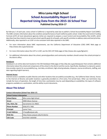
HotSPECIFICATIONSOutletColdPressures Max Static Pressure: 10 Bar.Max Maintained Pressure: 5 Bar.Min Maintained Pressure (Gravity System):0.1 Bar. (0.1 bar 1 Metre head from coldtank base to showerhead outlet).Note! For gravity fed / other low pressuresystems (0.5 bar or below) remove the outletflow regulator. Refer to section: ‘Installation,Flow Regulator’.For optimum performance supplies should benominally equal.Temperatures Optimum Thermostatic Control Range: 35 Cto 43 C (achieved with supplies of 15 C cold,65 C hot and nominally equal pressures).Dimensions340Recommended Hot Supply: 60 C to 65 CNote! The mixing valve can operate athigher temperatures for short periods withoutdamage, however this could detrimentallyaffect thermostatic performance. For safetyand performance reasons it is recommendedthat the maximum hot water temperature islimited to 65 C.Cold Water Range: up to 25 C.Minimum Recommended Differential betweenHot Supply and Outlet Temperature: 12 C.Thermostatic Shut-down 57145 Factory Pre-set (Blend) Shower: 43 C.1129 (ERD Models)1026 (ER Models) For safety and comfort the thermostat willshut off the mixing valve within 2 Seconds ifeither supply fails (achieved only if the blendtemperature has a minimum differential of12 C from either supply temperature).19011559ConnectionsThe thermostatic mixer can only be installed withrear supply inlets and the supply pipework mustbe connected as follows:Hot: Top (side nearest flow control), 15 mmcompression.107 All dimensions in mmCold: Bottom (side nearest temperaturecontrol), 15 mm compression.Outlet: 15 mm compression to rigid riser.Note! This product does not allow for reversedinlets and will deliver unstable temperatures iffitted incorrectly.6
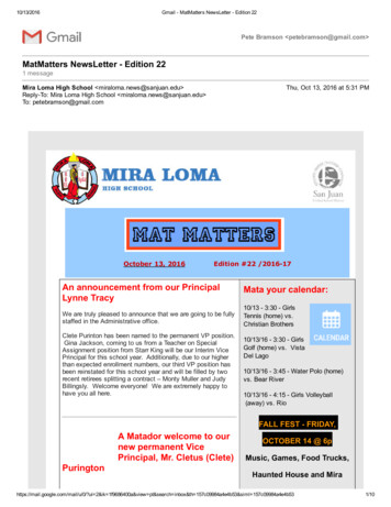
6. Decide on a suitable position for the Mixer,make sure that there is sufficient headroomand ceiling clearance to install the rigid riserrail and overhead pipe.Caution! Do not cut the rigid riser rail.For ERD models the position of the Mixer andthe Shower Fittings must provide a minimumgap of 25 mm between the spill-over level ofthe shower tray/bath and the showerhead(refer to illustration). This is to preventback‑siphonage.Note! Only use Shower Fittings recommendedby the manufacturer or supplier.INSTALLATIONSuitable Plumbing SystemsGravity Fed:The thermostatic mixer must be fed from a coldwater cistern (usually fitted in the loft space) anda hot water cylinder (usually fitted in the airingcupboard) providing nominally equal pressures.Mains Pressurised Instantaneous Hot WaterSystem (Combination Boiler):The thermostatic mixer can be installed withsystems of this type with balanced pressures.(Recommended Minimum Maintained Pressure:1.0 Bar).Unvented Mains Pressure System:The thermostatic mixer can be installed with anunvented, stored hot water system.Pumped System:The thermostatic mixer can be installed with aninlet pump (twin impeller). The pump must beinstalled in a suitable location and in accordancewith its instructions.25 mmSpill OverLevelGeneralInstallation must be carried out in accordancewith these instructions, and must be conducted bydesignated, qualified and competent personnel.The installation must comply with the “WaterSupply Regulations 1999 (Water Fittings)” or anyparticular regulations and practices, specified bythe local water company or water undertakers.Note! Make sure that all site requirementscorrespond to the information given in section:‘Specifications’.Flow RegulatorSite conditions will determine the flow regulatorrequirements.For gravity fed / other low pressure systems(0.5 bar or below) remove the outlet flowregulator.Outlet Flow Regulator1. The Mixer must not be installed in an areawhere it may freeze.2. For stud partitions alternative fixings may berequired.3. Isolating valves must be installed close to theMixer for ease of maintenance.4. Pipework must be rigidly supported and avoidany strain on the connections.5. Pipework dead-legs should be kept to aminimum.7
Installing the Thermostatic Mixer1. The thermostatic mixer must be fitted verticallyas illustrated and can only be installed withrear supply inlets. The supply pipework mustbe connected as follows: Hot to Top Inlet Cold to Bottom Inlet Top Outlet.Important! This product does not allow forreversed inlets.2. Determine the route for the hot and cold supplypipework.Important! Make sure that there is sufficientheadroom and ceiling clearance to install therigid riser rail and overhead pipe.HotOutletBackplateConcealing PlateInlet NutsCold6. Using the backplate as a guide, mark thepositions of the fixing holes and the pipecentres.Important! Make sure that there is sufficientheadroom and ceiling clearance to install therigid riser rail and overhead pipe.Note! Make sure that the backplate is thecorrect way up (refer to illustration).4. Loosen the 2 backplate grubscrews withthe 2 mm hexagonal key (supplied) andpull the mixer and concealing plate from thebackplate.5. Unscrew the inlet nuts from the backplate.Large boss must befitted at the bottom8
7. For solid walls drill the fixing holes for thebackplate with a 6 mm drill and insert thewall plugs (supplied). For other types of wallstructure alternative fixings may be required(not supplied).8. Drill the holes for the supply pipes and fit thesupply pipework:Hot to Top Inlet, Cold to Bottom InletNote! The inlet pipework should extendbetween 12 and 18 mm from the finished wallsurface.Caution! Make sure that the pipework is notdamaged otherwise the olives will not seal.9. Fit the backplate over the inlet pipes andsecure to the wall using the fixing screws(supplied).10.Caution! It is essential at this pointthat the supply pipework is thoroughlyflushed through before connection to themixer. Failure to do so may result in productmalfunction and will not be covered under theguarantee.11. Fit the olives onto the inlet pipework and tightenthe inlet nuts using a suitable spanner.Caution! Do not overtighten.Important! Make sure that the inlet filters arefitted in the inlet nuts as illustrated.12.Make sure that the concealing plate (withthe hole at the bottom) is loosely fitted overthe mixing valve inlets and align the mixerwith the inlet nuts. Push on fully and tightenthe grubscrews to secure the mixer to thebackplate. Make sure that the grubscrews areengaged fully in the valve body grooves.Concealing PlateInlet FiltersFixing Screws13.Push the concealing plate onto the backplate,secure with the M4 x 12 mm grubscrew.Single grubscrew securesthe top inlet to the backplateHot InletInlet NutOliveCold InletFilterLarge boss must befitted at the bottomTwo grubscrews secure both thebottom inlet and the concealingplate to the backplate9
14.Important! A 12 litre/minute flow regulator isfitted inside the outlet This can be removedfor gravity fed / other low pressure systems(0.5 bar or below).16.Screw the rigid riser rail into the rigid riseroverhead pipe.Note! If your rigid riser rail is supplied in twoparts, first screw them together.17.Locate the rigid riser rail into the divertor /mixing valve outlet and the rigid riser overheadpipe into the securing bracket, make sure thatthey are pushed fully home.Important! Align the rigid riser overhead pipewith the securing bracket using the pin. Use aspirit level to make sure that the rigid riser railis vertical and mark the position of the fixingholes for the securing bracket on the wall.Caution! Do not cut the rigid riser rail.18.For solid walls drill the fixing holes for thesecuring bracket with a 6 mm drill and insertthe wall plugs (supplied). For other typesof wall structure alternative fixings may berequired (not supplied).19.Secure the securing bracket to the wall usingthe screws (supplied).Outlet Flow Regulator15.For ERD models fit the divertor onto the mixeroutlet and tighten the M4 x 6 mm grubscrewwith a 2 mm hexagonal key (supplied).The divertor must be fitted as illustrated, withthe divertor knob at the front and the outlet tothe right of the mixing valve.Securing BracketFixing ScrewsSecuring BracketCoverRigid RiserOverhead PipePinDivertorSpirit Level10Rigid RiserRail
20.For ER models slide the concealing plate,compression nut and olive onto the rigid riserrail and locate it into the mixer outlet.21.For ERD models slide the clamp bracket, hoseretaining ring, compression nut and olive ontothe rigid riser rail and locate it into the divertoroutlet.22.Make sure that the securing bracket cover isfitted onto the rigid riser overhead pipe, thenfix the pipe to the securing bracket with thepin. Screw the securing bracket cover overthe securing bracket.23.Tighten the compression nut using a suitablespanner.Note! Hold the divertor in position whilsttightening the compression nut.24.For ER models slide the concealing plate downthe rigid riser rail to cover the compressionnut.25.For ERD models:25.1 Screw the hose onto the outlet of thedivertor, making sure that the hose sealis fitted.25.2 Pass the flexible hose through the hoseretaining ring and screw the remainingend of the hose onto the showerheadmaking sure that the hose seal is fitted.25.3 Place the showerhead in the clampbracket.26.Make sure that the hose washer is fitted andscrew the deluge head onto the rigid riseroverhead pipe.Rigid RiserOverhead PipeSecuring BracketHose WasherDeluge HeadPinSecuring BracketCoverClamp Bracket27.Turn on the hot and cold water supplies andcheck for leaks.28.Before using the shower, refer to section:‘Commissioning’.Hose e Seal11
COMMISSIONINGOPERATIONCaution! Care is required when adjustingflow, diverting to different outlets or adjustingtemperature. Make sure that the temperaturehas stabilised.Maximum Temperature SettingBefore using the shower the maximum temperaturemust be checked to make sure that it is at asafe level. It has been preset to approximately43 C at the factory but due to variations in siteconditions the maximum temperature may needadjustment.Note! Make sure that the hot water temperature isat least 55 C and that there is sufficient supply.1. Turn on the mixer to the maximum temperature(i.e. fully clockwise) and allow the temperatureto stabilise.2. Test that the temperature of the water from theshower outlet is hot enough.If the temperature is too hot or too cold adjustas follows:3. Carefully remove the concealing cap using asuitable tool (i.e. stanley knife / thin blade).4. Loosen the securing screw (do not removefully) and pull down the temperature lever todisengage from the control gear.5. Rotate the temperature lever anti-clockwise(one serration), re-engage with the controlgear and return to the maximum temperaturestop. Check the temperature, if it is still not hotenough repeat the procedure.Operating the Divertor(ERD Models Only) The flow is switched betweenthe deluge head, the showerhead and bothtogether by rotating the divertor knob.Note! On gravity fed / other low pressure systemswith both outlets operating, the height of theshowerhead may affect the flow from the delugehead.Flow ControlTurn the flow lever anticlockwise to the maximumflow.Temperature ControlTurn the temperature control lever anticlockwiseto decrease the temperature and clockwise to thepreset maximum alingCapStanley Knife/ Thin BladeFlow ControlPull down and rotatethe temperature leverto adjust the maximumtemperature.OnOff-ConcealingCap Lug 6. Once the maximum temperature is satisfactory,tighten the securing screw.7. Refit the concealing cap with the lug at theback (i.e. nearest the wall) make sure thatthe rubber seal is correctly fitted and theconcealing cap is pushed fully on.12TemperatureControl
LubricantsUSER MAINTENANCESilicone based lubricants must only be used onthe rubber seals.Caution! Oil based or other lubricant types maycause rapid deterioration of seals.If you require a Mira trained service engineer oragent, refer to section: ‘Customer Services’.Fault DiagnosisCleaningSymptom:Only hot or cold water from the mixer outlet. The chrome plated parts should be cleaned usinga mild washing up detergent or soap solution,rinsed and then wiped dry with a soft cloth.Warning! Many household cleaners containabrasive and chemical substances, and should notbe used for cleaning plated or plastic fittings.These finishes should be cleaned with a mildwashing up detergent or soap solution, and thenwiped dry using a soft cloth.Use your thumb or a soft cloth to wipe anylimescale from the soft nozzles and the frontsurface of the showerhead spray plate.Do not use descalents on this product.Outlet temperature too hot / too cold.Cause Rectification:Inlets reversed (hot supply to cold supply).Rework inlet pipework. No hot water reaching mixer.Check the filters for any blockage.Installation conditions outside operatingparameters, refer to sections: ‘Specifications’and ———Symptom:Fluctuating or reduced flow rate. Cause Rectification:Check the showerhead, hose and filters forany blockage. Make sure that the maintained inlet pressuresare nominally balanced and sufficient, referto section: ‘Specifications’.Make sure that the inlet temperaturedifferentials are sufficient, refer to section:‘Specifications’.Flow regulator fitted incorrectly.Air lock or partial blockage in the mptom:Water leaking from showerhead. Cause Rectification:Normal for a short period after shut off. Check that the pressures are not in excess ofthe specifications for the product.Renew the mixer valve assembly.13
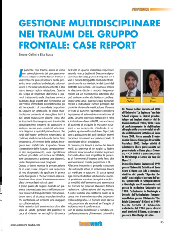
SPARE PARTS1660.176Concealing CapAssembly (Miniluxe)1660.177Outlet Connector(ERD models)1663.265Flow Regulator Pack1660.150Backplate1660.151Concealing Plate1660.152Filter Pack (x2)1660.157Flow Knob Pack(Miniluxe)1660.182Flow Knob Pack(Stylus)1660.153Inlet Nuts & Olives (x2)1660.185Mixer Valve Assembly (Stylus)1660.186Mixer Valve Assembly (Miniluxe)Note! Knobs vary depending on model.Mixer Valve Assembly also includes1660.151 - Concealing Plate.Not illustrated:1660.159 Screw Pack1660.175 Seal Pack1660.155Temperature KnobPack (Miniluxe)141660.182Temperature KnobPack (Stylus)
1660.162Fixing Pack1660.160Rigid Riser Overhead Pipe1660.161Deluge Head1660.163Rigid Riser Rail1663.190Showerhead1603.137Flexible Hose1660.178CompressionNut & Olive1660.172Clamp Bracket (Stylus)1660.179Clamp Bracket (Miniluxe)1660.173Hose RetainingRing1660.165Divertor Assembly (Stylus)1660.276Divertor Assembly (Miniluxe)15
ACCESSORIESACCESSORIESGenuine Mira accessories can be purchased direct from Customers Services (our contact details canbe found on the back cover of this guide) or from approved stockists or merchants.Eco ShowerheadWhite - 2.1668.001Chrome - 2.1668.002The Eco shower head givesyou an invigorating shower, butreduces water consumption andheating costs.Everclear ShowerheadWhite - 2.1616.030Chrome - 2.1616.031Mira's new Everclear range hasbeen specially designed for hardwater areas and reduces the riskof lime scale build up.Shower SeatWhite - 2.1536.128White/Chrome - 2.1536.129For use in or out of theshowering area. Note! Must beinstalled onto a solid wall.Shower seat folds up when notin use16Wall Mounted Soap DishWhite - 1.1540.278Chrome - 1.1540.279Wall mounted for use anywherein, or outside the showeringarea.
NOTES17
NOTES18
NOTES19
CUSTOMER SERVICEGuaranteeWhat to do if something goes wrongYour product has the benefit of our manufacturer’sguarantee which starts from date of purchase. Thisguarantee only applies in the United Kingdom andRepublic of Ireland. To activate this guarantee, pleasereturn your completed registration card, visit ourwebsite or free phone 0800 5978551 within 30 daysof purchase (UK only).If your product does not work correctly refer to thismanual for fault diagnosis and check that it is installedand commissioned in accordance with our instructions.If this does not resolve the issue, contact us for helpand advice.Helpdesk ServiceContact our Customer Services Team forproduct advice, to purchase spare parts oraccessories or to set up service visit. You can contactus via phone or e-mail - contact details below.Please provide your model name, power rating (ifapplicable) and date of purchase.Within the guarantee period we will resolve defects inmaterials or workmanship, free of charge, by repairingor replacing parts or product as we may choose.This guarantee is in addition to your statutoryrights and is subject to the following conditions :Mira Showers Website(www.mirashowers.co.uk)Visit our website to register your guarantee,download user guides, diagnose faults, purchaseour full range of accessories and popular spares, orrequest a service visit. The guarantee applies solely to the originalinstallation under normal use and to the originalpurchaser only. The product must be installed andmaintained in accordance with the instructionsgiven in this guide. Servicing must only be undertaken by us or ourappointed representative.Note! If a service visit is required the product mustbe fully installed and connected to services. Repair under this guarantee does not extendthe original expiry date. The guarantee on anyreplacement parts or product ends at the originalexpiry date. For shower fittings or consumable items wereserve the right to supply replacement parts only.The guarantee does not cover:Spares and AccessoriesWe hold the largest stocks of genuine Miraspares and accessories.Contact us for aprice or visit our website to purchase items from ouraccessory range and popular spares. (Only availablein the United Kingdom )Service/RepairsNo one knows our products better than ournationwide team of Service Technicians. Wecan carry out service or repair work to your productboth during and after the guarantee period. (Onlyavailable in the United Kingdom and Republic ofIreland) Ask about our fixed price service repairs.To Contact Us: UK Call out charges for non product faults (such asdamage or performance issues arising fromincorrect installation, improper use, inappropriatecleaning, lack of maintenance, build up oflimescale, frost damage, chemical attack,corrosion, system debris or blocked filters) orwhere no fault has been found with the product. Water or electrical supply, waste and isolationissues. Compensation for loss of use of the product orconsequential or indirect loss of any kind. Damage or defects caused if the product isrepaired or modified by persons not authorised byus or our appointed representative. Routine maintenance or replacement parts torepaired or modified by persons not authorised bycomply with the requirements of theTMV2 orrepaired or modified by persons not authorised byTMV3 healthcare schemes Accidental or wilful damage. Products purchased ex-showroom display.0844 571 5000Calls cost 7p per minute plus your phone company’saccess chargeFax: 01242 282595Email – Visitwww.mirashowers.co.uk/contactusBy Post: Mira Customer Services Dept, CromwellRoad, Cheltenham, Gloucestershire GL52 5EPTo Contact Us: Eire Only01 531 9337E-mail:CustomerServiceEire@mirashowers.comMira is a registered trade mark ofKohler Mira Limited.The company reserves the right to alterproduct specifications without notice.146481083351-W2-F (B94F) (1663)20 Kohler Mira Limited, April 2016
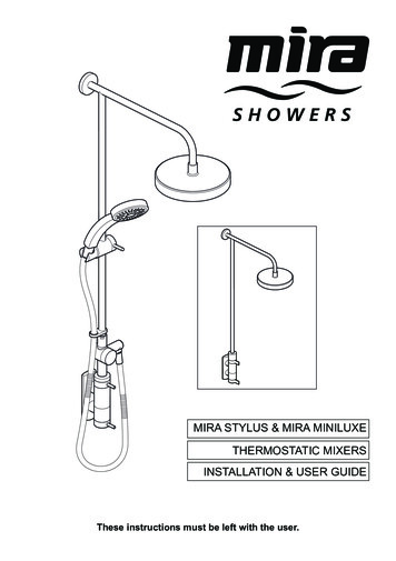
The Mira Stylus and Mira Miniluxe are thermostatic mixers which have separate flow and temperature controls. The Mira Miniluxe ER is an exposed valve supplied with a rigid riser to a deluge head. The Mira Stylus ERD and Mira Miniluxe ERD are exposed valves supplied with a rigid riser to a deluge head and a divertor assembly, single mode