Transcription
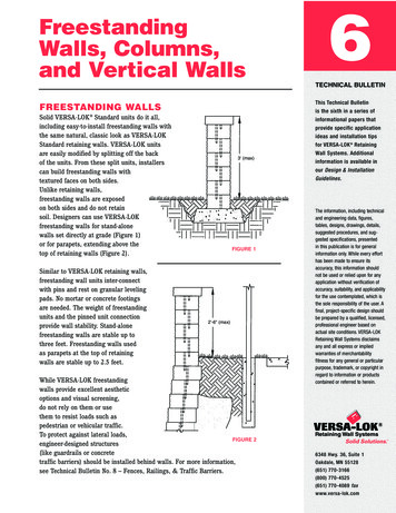
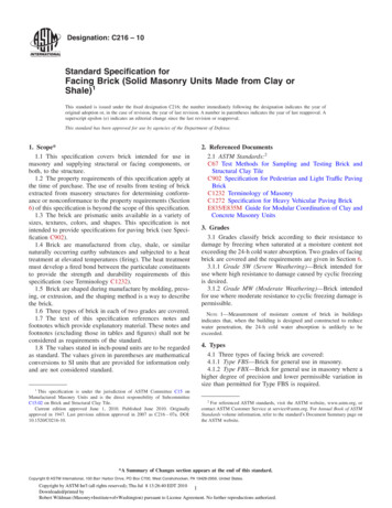
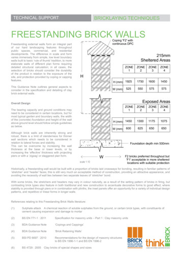
BRICKLAYING TECHNIQUESTECHNICAL SUPPORTFREESTANDING BRICK WALLSFreestanding external walls form an integral partof our hard landscaping features throughoutpublic spaces, commercial, and residentialdevelopments. The difference in scale and formvaries immensely from simple, low level boundarywalls built to basic ‘rule of thumb’ tradition, to moreelaborate walls of different plan forms requiringdetailed structural calculation; in all cases, theselection of bricks should consider the durabilityof the product in relation to the exposure of thesite, and protection provided by coping or cappingfeatures.Coping 'F2' withcontinuous DPC215mmSheltered AreasZONE1ZONE2ZONE3ZONE4HHThis Guidance Note outlines general aspects toconsider in the specification and detailing of claybrick external walls.H (mm) 1925175016001450525550575575W (mm)Exposed AreasOverall DesignZONE1The bearing capacity and ground conditions mayneed to be considered in certain locations, but formost typical garden and boundary walls, the widthof the (concrete) foundation and height of the wallabove ground level should follow simple guidelinesas below.ZONE2ZONE3ZONE4H (mm) 1450130011751075600625650650W (mm)Although brick walls are inherently strong androbust, there is a limit of slenderness for thinnerwall sections which needs to be considered inrelation to lateral forces and stability.This can be overcome by increasing the wallthickness at the base or lower levels, or byincreasing the ‘effective’ thickness with projectingpiers or with a ‘zigzag’ or staggered plan form.DPbr'FduFoundation depth min 500mmWF2 bricks preferred throughout but'F1' acceptable in more shelteredlocations with suitable protectionscale 1:10Historically, a freestanding wall would be built with a proportion of bricks laid crossways for bonding, resulting in familiar patterns of‘stretcher’ and ‘header’ faces; this is still very much an acceptable method of construction, providing an attractive appearance, andavoiding the necessity of wall ties between two separate leaves of ‘stretcher’ bond.With some bricks, the stretchers and headers may vary in colour naturally, as a result of the setting pattern of bricks in firing, butcontrasting brick types also feature in both traditional and new construction to accentuate decorative forms to good effect; wherestability is provided through piers or in combination with plinths, the inset panels offer an opportunity for a variety of individual designpatterns, and repetitive or linear forms in longer walls.BDA - FreestandinReferences relating to this Freestanding Brick Walls literature:(1)Sulphate attack A chemical reaction of soluble sulphates from the ground, or certain brick types, with constituents ofcement causing expansion and damage to mortar(2)BS EN 771-1 : 2011Specification for masonry units – Part 1 : Clay masonry units(3)BDA Guidance Note‘Copings and Cappings’(4)BDA Guidance Note‘Brick Retaining Walls’(5)BSI PD 6697 : 2010(6)BS 4729 : 2005Recommendations for the design of masonry structuresto BS EN 1996-1-1 and BS EN 1996-2Clay bricks of special shapes and sizes
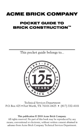
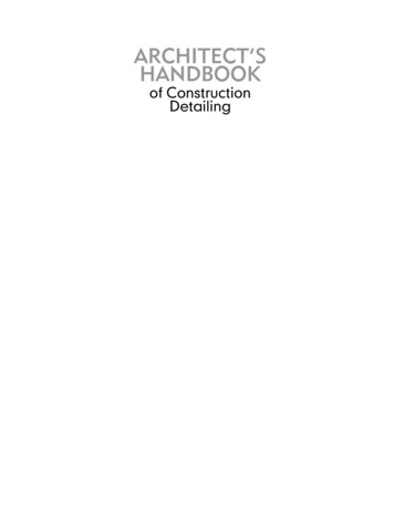
BRICKLAYING TECHNIQUESTECHNICAL SUPPORTFREESTANDING BRICK WALLSDurabilitymmeas327mmSheltered AreasONE4ZONE1ZONE2ZONE3ZONE4H50H (mm) 250025002500245075W (mm)525575650725easExposed 4H (mm) 2400217520001825725775800850W (mm)UK Wind Exposure Zones 1 to 4(based on wind distribution)mmt buteredctionZONE2scale 1:10WSheltered and Exposed Areasrelate to local conditions, e.g.urban and open ruralIt is important that the bricks chosen forexternal walls are of suitable durability toprovide long term resistance to the effectsof weathering and exposure, includingfrost and sulphate attack(1). The productStandard BS EN 771-1 : 2011(2) requiresmanufacturers to classify products inrelation to exposure categories, anddesignation ‘F2’ is considered mostsuitable for detailing, particularly inlocations of severe exposure.An appropriately detailed protectivecoping should be provided. (AnotherGuidance Note (3) is available whichillustrates cappings and copings).It should also be recognised that thewater absorption characteristic of a brickis related to the method of manufacturing,and is not a direct influence on thedurability performance. A brick of ‘F2’designation can be used throughoutthe wall, but where a more ‘rustic’ brick(of high water absorption) is selected,specifiers often consider a contrastingbrick of smooth appearance and lowwater absorption for capping elementsand for the base courses; set in a strongmortar, this can assist in avoiding longerterm staining of brick surfaces and mortarjoints, and avoids the requirement for ahorizontal damp proof course at lowlevel, which would weaken the stability ofthe wall if installed incorrectly.In many residential developments, the ground level to either side of garden walls may vary, and this may require inclusion of amembrane to prevent water (and ground salt) migration from the higher level, although specific reference to detailing of ‘retainingwalls’ is made in another Guidance Note (4).Where paving is the finished surface to either side, this should be laid to falls away from the wall where possible, or provision madefor a drainage strip to prevent unnecessary saturation of the lower courses.tanding Brick Wall Details
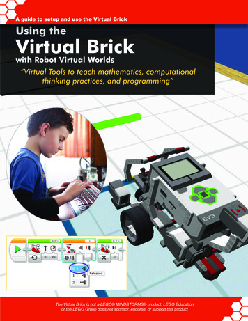
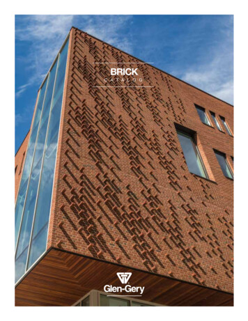
BRICKLAYING TECHNIQUESTECHNICAL SUPPORTFREESTANDING BRICK WALLSMortarThe durability of the mortar is most importantespecially for more exposed elements andreference should be made to BSI documentPD6697(5) Recommendations for the design ofmasonry structures which recently replace theformer code of practice BS 5628 part 3.For copings and cappings, and for base courses,a category ‘M12’ mortar should be used, with asimilar strength throughout the wall in areas ofsevere exposure. For more moderate exposure aclass ‘M6’ or ‘M4’ can be considered although thelatter should not be used where a brick of highersoluble salts content (category ‘S1’) is specified,to avoid potential salt migration and expansivereaction with the mortar (1).scale 1:10Movement jointsEnglish Garden WallFreestanding walls (and external parapetconditions) tend to be less restrained than wallsof buildings, and are subjected to more horizontalmovement potential, requiring adequate provisionfor vertical movement joints; as a general guide,joints should be considered at 5 – 6 metre centres,with a 3 metre centres for capping features, andmain joints must extend from the base coursebelow ground level, through to the coping orcapping element.(3 course stretchers betweenheader courses)It is important to select acompressible joint filling material,and proprietary products arereadily available; fibreboard andcork based materials are notsuitable however, particularlywhen wet, as this significantlyreduces the already limitedcompaction.Gun appliedsealants can provide an attractivefinish to the joint, with a range ofcolours to match or contrast withthe brick finish.The practice of leaving a small(10mm) gap between linearwalls may achieve a suitableseparation in some cases, but caneasily result in mortar blocking thespace becoming ineffective, withissues of continuity through thecoping or capping.scale 1:10Flemish Garden Wall(3 stretchers then cross bonding headers)
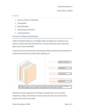
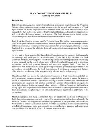
BRICKLAYING TECHNIQUESTECHNICAL SUPPORTFREESTANDING BRICK WALLSIf ground level to one sideraised, consider membrane toprevent migration of water/saltsWall FeaturesThe simplest form of freestanding wall isof linear design with a consistent numberof courses throughout, finished with acapping or coping in a horizontal plane.With sloping sites, this may result in aseries of stepped sections, requiring aspecial end detail for the coping element;even with a basic brick on edge capping,solid units (preferably faced on bed)should be specified, or larger blocks withfaced sides.Where access is required, a commonfeature at each end of the break in thewall is a column or pier, providing asuitable fixing for a gated entrance. Theheight of the brick wall may provideenclosure, but in many residential areasthe boundary wall may comprise a seriesof intermediate piers projecting upwardlyfrom a lower wall, providing support formetal railings or timber screen panelsin-between. The fixings should takeinto account the potential characteristic(differential) movement through weathercycles, but also with timber fencing,resistance to wind pressure, causing alocal stressing of the brick pier; brickworkshould therefore be of good quality witha strong mortar and completely filledmortar joints.Both metal railings and particularly timberpanels require periodic maintenance,and observations of the latter highlightthe run-off of water and detritus causinga local saturation and staining of cappingfeatures and brickwork below.F2 bricks required tomin 150mm aboveground levelpreferably fall awaywith hard landscapingpaving/land surfacesideally sloping away fromwall or drainage detail fall.scale 1:10BDA - Freestanding Brick Wall
BRICKLAYING TECHNIQUESTECHNICAL SUPPORTFREESTANDING BRICK WALLSAngled WallsAt changes of direction in plan, external and internal shaped angles should be incorporated to avoid the unsightlyappearance of standard bricks overlapping; the British Standard for units of special shapes(6) includes a range ofangled bricks developed to take into account the dimensions of bonding bricks – historically with cross bonding,resulting in ‘quarter’ bond, or the simple ‘squint’ brick which allows stretcher bond to continue around the angle.The layout of the site boundary or landscaping feature may dictate changes of angle otherthan the ‘standard’ 30, 45, or 60 degrees in the British Standard. This is not generally anissue for manufacturers who can provide purpose made units for external or internal angleapplications. Appropriate specials would also be needed of course for any features suchas plinths and cappings around the angle.similarly with 'External Angle'AN.1.1 'Squint' brick resulting in 'half' lap - stretcher bondAngled Wall using Squint Bricksimilarly with 'External Angle'AN.2.1 'Internal Angle' brick resulting in 'quater' lap e.g. english and flemish bond variationsAngled Wall using External Angle Brickscale 1:10An alternative to ‘manufactured’ specials is the fabrication, or cutting and bonding, ofstandard bricks to form specific angles. The technique can be successful avoiding mouldor die costs in production, but should be carried out in controlled conditions within a suitableenvironment, and good quality control is essential.
TECHNICAL SUPPORTBRICKLAYING TECHNIQUESFREESTANDING BRICK WALLSBrick Wall ProfilesWall Features215mm 'conventional' walls327mm 'conventional' wallsstaggered profile, beware unfacedsides with some brick types(particularly wirecut/extruded)effective thickness increased by piersstability achieved with columns/piersat either endoption for additional stability with piersto both sides and plinth detail to one orboth sidescurve on plan to increase effectivethicknessscale 1:10In more open developments,continuous metal railings may beprovided for decorative or safetyreasons over lower freestandingwalls. Clearly a sound fixing isrequired, but this should not berigid enough to create stressingof the bricks locally, particularlyif fixed directly to a brick onedge capping, and for longersections (allowing for differentialmovementbetweenmetalrailings and brickwork support)a series of balusters anddetailed joints is recommendedrather than continuously weldedsections.A brick of low water absorptionset in a strong mortar ispreferable to a horizontalmembrane dpc in the basecourses. It is advisable howeverto include a dpc sandwiched inmortar immediately below thecoping or capping, to preventthe downward movement ofwater (through mortar joints).Where a more robust detail ispreferred, particularly in areas ofpublic contact or vandalism, it isaccepted practice to include thedpc at a lower level but withinthe upper courses.Traditionally built walls mayincorporate a tile creasingwhich can assist in projectingwater away from coursesbelow, but a membrane dpc isstill recommended for a moreresistant detail.
BRICKLAYING TECHNIQUESTECHNICAL SUPPORTFREESTANDING BRICK WALLSFreestanding walls may also be curved on plan to follow siteboundaries or to provide effective thickness in a ‘serpentine’form of gentle radius. Although the British Standard for specialshapes includes a range of ‘radial stretchers’ these are ofconvex faces and only suitable therefore for external curves –applicable mainly for the outer leaf of buildings. It is possibleto use standard bricks however to form a general curve, andwith stretcher bond a threshold radius of 4 metres provides acurve without unsightly overlap in alternate courses. (With bricksof characteristic irregular arrises such as handmade units, thethreshold can be reduced to 3.5 metres).Curved WallsAdopting header bond will also achieve a reduced curve, bycreating more facets; in a full brick width wall and cross bonded,this will be limited by the acceptable tapering of mortar jointsvisually, on both sides of the wall. It should also be rememberedthat the ‘header’ faces may not be of the same colouring asadjacent sections of stretcher brickwork, and with an increase inthe mortar proportion, the curved element may stand out.Curve can also be limited totaper of mortar joint withstandard facingsWhere tighter radii are required, this may involve purpose madespecials, of both convex and concave profile.With obtuse angles an unsightly overlap will occur andwill therefore be unsuitable. Only with an acute angleand smaller radii can a standard brick be used.Radial Bricks are preferable as they can perform smooth cylindrical facades.Convex Facing Bricks are usedfor 'external' conditions.Concave Facing Bricks arerequired for 'internal' conditions.These come with either astraight or radiated back faceRadiusRD. 2 Radial Stretcher 'convex'(R)Brick face line of chord (L)Guidance for half lap/stretcher bond min. radius 3.5 to 4.0 metresTighter radius with header bond but determined by acceptable taper ofmortar joints.For Caluclation:overlap 'h'line of arcscale 1:10overlap h R-R2- (0.5L)2
wall is a column or pier, providing a suitable fixing for a gated entrance. The height of the brick wall may provide enclosure, but in many residential areas the boundary wall may comprise a series of intermediate piers projecting upwardly from a lower wall, providing support for metal railings or timber screen panels in-between.