Transcription
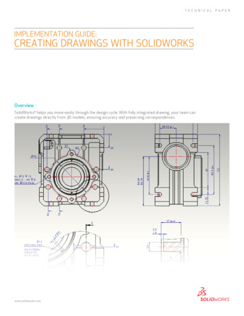
TECHNICALimplementation guide:creating drawings with solidworksOverviewSolidWorks helps you move easily through the design cycle. With fully integrated drawing, your team cancreate drawings directly from 3D models, ensuring accuracy and preserving correspondences.www.solidworks.comPAPER
You can generate drawings in SolidWorks the same way you would generate themin 2D drafting and drawing systems. However, creating 3D models and generatingdrawings from the models has many advantages; for example: Designing models is faster than drawing lines. SolidWorks creates drawings from models, so the process is efficient. You can review models in 3D and check for correct geometry and design issuesbefore generating drawings, so the drawings are more likely to be free ofdesign errors. You can insert dimensions and annotations from model sketches and features intodrawings automatically, so you do not have to create them manually in drawings. Parameters and relations of models are retained in drawings, so drawings reflectthe design intent of the model. Changes in models or in drawings are reflected in their related documents, somaking changes is easier and drawings are more accurate.Creatin DrawingsDrafting in SolidWorksTo draft a drawing in SolidWorks without creating a model:1. Open a Newdrawing document. Choose a template.2. Draw lines, rectangles, circles, and other entities with the tools on the Sketchtoolbar.3. Dimension the entities with the Smart Dimensiontool on theDimensions/Relations toolbar.4. Add annotations (Notes, Geometric Tolerance Symbols, Balloons, and so on)with tools on the Annotation toolbar.NOTE: See the next section for an alternative approach. See Drafting for furtherdetails on sketching in drawings.2 Implementation Guide: Creating Drawings with SolidWorks www.solidworks.comCreating and placing any views canbe done with just a few mouse clicks.Intelligent toolsets automaticallydimension components to ensureyour designs have the necessarymanufacturing information.
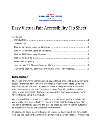
Creating Drawings from ModelsTo generate drawings from part and assembly documents:1. In a part or assembly document, click Make Drawing from Part/Assemblyon the Standard toolbar and select a template in the Sheet Format/Sizedialog box.The View Palette opens on the right side of the window.2. Clickto pin the View Palette.3. Drag a view from the View Palette onto the drawing sheet.4. In the Drawing View PropertyManager, set options such as orientation, displaystyle, scale, etc., then click.5. Repeat steps 3 and 4 to add views.Note: You can have any drawing views of any models in a given drawing document.Model part Drawing with several views and dimensions inserted3 Implementation Guide: Creating Drawings with SolidWorks www.solidworks.com
DraftingYou can draft in 2D in SolidWorks drawing documents using Sketch tools,Dimension tools, and Annotations as described in Creating Drawings. Concepts toconsider include:Sketch entities In SolidWorks drawing documents, you can add sketch entities(lines, circles, rectangles, and so on) at any time. You can createyour own line styles using layers, the Line Format tools, or LineStyle Options.Drawing viewsYou can add sketch entities and annotations to the drawingsheet or to drawing views. Drawing views allows you to moveand scale all the items in the view in one operation. You caninsert empty views onto drawing sheets to contain draftedentities.Standards The drafted elements follow the standard specified in Tools,Options, Document Properties, Drafting Standard. Such itemsas dimension arrows, tolerances, annotation display, and soon are generated based on the standard, but you can also editthe items manually (choose a different arrowhead style, forexample).Sheet formatsSolidWorks drawing templates contain drawing sheet formats.You can edit the formats and save them. You can also use atemplate without the format and create your own format, orimport a block from your 2D CAD system (a title block, forexample).Grid To display a grid, right-click and select Display Grid. Specifythe grid spacing and snap control in Tools, Options, DocumentProperties, Grid/Snap.DimensionsDimensions in SolidWorks control the geometry. The sketchentity or model element must agree with its dimension.You cannot sketch an entity at a certain size and display adimension of a different size. However, you can scale entities ina drawing sheet or drawing view.RelationsRelations (such as Horizontal, Concentric, Tangent) alsocontrol geometry. Some relations are inferred as you sketch.You can add, display, and delete relations. To preventautomatic relations, press Ctrl as you sketch, or clearAutomatic relations in Tools, Options, System Options,Sketch, Relations/Snaps.Annotations Most annotations work with sketch entities the same as theydo with drawings derived from 3D models. Some exceptionsare hole callout and autoballoon. Single balloons and stackedballoons appear with question marks, which you can replacewith custom text. You can import into drawings thedimensions and tolerances you create with DimXpert for parts.4 Implementation Guide: Creating Drawings with SolidWorks www.solidworks.comStandard templates and automateddrawing checks streamline commondesign checking tasks.
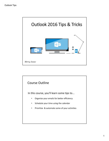
StandardsYou can set up styles in SolidWorks to format dimensions, but it is not necessaryto do so for dimensions and other annotations to follow a drawing standard.In SolidWorks, you set the standard for the current document in Tools, Options,Document Properties, Drafting Standard. The standard can be ANSI, ISO, DIN, JIS,BSI, GOST, or GB.You can also set the standard in a drawing document template.ANSI IOSDIN JISBSI GOSTGB5 Implementation Guide: Creating Drawings with SolidWorks www.solidworks.com
ScalingIn SolidWorks, drawing views can be at any scale (2:1, 1:2, for example) in relation tothe model.Drawing SheetsYou can set separate scales for each drawing sheet in the Sheet Properties dialogbox. Right-click the drawing sheet outside any drawing views and select Properties.The scale of a drawing sheet appears in the status line at the bottom of theSolidWorks window.Drawing ViewsThe scale of a drawing view is set in the PropertyManager when you select theview in the graphics area. A drawing view uses the scale of the drawing sheetunless: You specify another scale, either when creating the view or any timeafterwards.- or The software needs to fit the view on the sheet with a certain scale.Your drawings are an importantpart of how you communicate withyour manufacturers, and SolidWorkssoftware provides the tools to createcomprehensive drawings of your design.Your 2D drawing is automatically linkedwith your 3D model. When the 3D modelis modified, the 2D drawing can beupdated automatically, ensuring thatyour drawing views are up to date andthe drawing to scale.When you create a child view (Section View, Detail View, and so on), the scale ofthe child view can be the same as the parent view, the same as the drawing sheet,or a custom scale. This section view has the same scale as its parent view.6 Implementation Guide: Creating Drawings with SolidWorks www.solidworks.com
Multiple DrawingsIn SolidWorks, you can have multiple drawing sheets in a drawing document, whichis like having a set of drawings all in the same file. The sheets can contain drawingviews of any parts or assemblies. You can switch between sheets by selecting anamed tab at the bottom of the SolidWorks window. You can also add and deletesheets using the shortcut menu.Title BlocksWhen you start a new drawing in SolidWorks, you select a template with a specifiedpaper size and drawing sheet format. The format can be standard, customized, orno format (specifying size only). When you define a title block, you can specifywhich template fields are editable and hotspot areas you can click to enter titleblock data.Standard formats contain title blocks. SolidWorks allows you to edit the sheetformat. (You can also save sheet formats for use in future drawings.) You can add,move, format, and delete lines and text.You can link note data to document properties such as file name, date, sheetnumber, and so on, or to custom properties that you define.The title block in a default landscape sheet format contains the following linesand text:In this example of editing the sheet format, a note with the company name is added,the note with the drawing name is edited, the lines are thickened, and a graphic isadded.Drawing Views7 Implementation Guide: Creating Drawings with SolidWorks www.solidworks.com
Drawing views are containers. Generally the contents are views of models. Whenyou sketch in a drawing, or insert annotations or blocks, the entities belong to theactive drawing view or drawing sheet. In SolidWorks you create drawing viewsas follows: Standard views, such as standard 3 views, various named model views (such asisometric), and relative views created automatically from the model. Derived views (projected, auxiliary, section, detail, broken, broken-out section,alternate position views) created in one or two steps from another view (suchas drawing a profile for a detail view). Empty views (for sketch entities, notes, and so on) inserted with the menuitem Insert, Drawing View, Empty.Any changes in the model are automatically reflected in the drawing views.Aligning ViewsAlignment between views in SolidWorks is automatic and adjustable. For example,standard 3 views are automatically aligned vertically and horizontally, while section,projected, and auxiliary views are aligned in the appropriate direction.You can drag the views within the correct alignment. You can also break thealignment and drag views anywhere on the drawing sheet. You can rotate viewsand hide or show views.Drawing views are containers.Generally the contents are views ofmodels. When you sketch in a drawing,or insert annotations or blocks, theentities belong to the active drawingview or drawing sheet.Standard 3 views are aligned automatically. The top view is constrained horizontallyand the right view is constrained vertically by default.8 Implementation Guide: Creating Drawings with SolidWorks www.solidworks.com
Section views are aligned automatically in the direction of the cut. Detail views are not aligned.Dimensions in DrawingsUsually you specify dimensions when you design a part, then insert the dimensionsfrom the model into the drawing. Changing a dimension in one document changes itin any associated documents.NOTE: You can set an option during installation of SolidWorks that preventschanges in dimensions in drawings from affecting part or assembly models.In SolidWorks, dimension formatting follows the standard that is set for thedocument in Tools, Options, Document Properties, Drafting Standard by default.You can change the document or template defaults for each type of dimension listedunder Tools, Options, Document Properties, Dimensions. SolidWorks uses styles tosave particular formatting.Reference dimensions cannot be modified and do not change model geometry.However, when a model changes, reference dimensions update automatically. Modeldimensions are linked to the model parametrically, using dimension names, and, whenchanged (in drawings or in model documents), modify the model.When you insert dimensions in part and assembly documents, they are marked fordrawings unless you specify otherwise. When you insert model dimensions withModel Items, automatically for a new drawing view, or with Autodimension, only thedimensions marked for drawings are inserted. When you insert an annotation viewinto a drawing, all annotations in the part or assembly are inserted in the drawing.9 Implementation Guide: Creating Drawings with SolidWorks www.solidworks.comWith expert tools for dimensioning andtolerancing, you can spend more time ondesign and less on drawing cleanup.
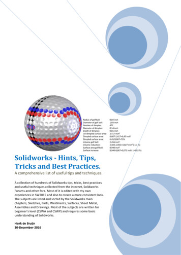
Dimensions define the geometry in the model sketches.The model dimensions are transferred into the drawing using insert,model items.Baseline dimensions, ordinate dimensions, chamfer dimensions, and hole callouts areavailable in drawings. Ordinate dimensions are also available in sketches.Baseline dimensions Ordinate dimensionsChamfer dimensions Hole callout10 Implementation Guide: Creating Drawings with SolidWorks www.solidworks.com
Dimension FormatsYou can format dimensions individually or as a group in sketches and drawings. Ifyou select a group of dimensions, only those properties the dimensions have incommon are available for editing.Editing in the Graphics AreaTo position dimensions, select and drag them. To change the direction of the arrows,click the circular handles. Several display options, such as Show Parentheses andInspection Dimension, are available in the Dimension Value PropertyManager.In the following example, the arrows are flipped, the parentheses removed, and thedimension value centered.Before AfterPropertyManagersSelect the dimension (or dimensions) and edit properties in these PropertyManagers: Dimension Value PropertyManager Dimension Leaders PropertyManager Dimension Other PropertyManagerThe PropertyManager properties include: Dimension Style Tolerance/Precision Witness/Leader Display Dimension Text (including alignment and symbols) Primary Value Display Options Break Lines LayerIn this example, the arrow style has been changed (from the default open arrowsto solid arrows) and tolerance and text have been added in the DimensionPropertyManager.Before After11 Implementation Guide: Creating Drawings with SolidWorks www.solidworks.com
Other properties you can modify using the PropertyManagers include: Value Name Units Precision Font Various check boxes and buttonsIn this example, you modified the font size and style, then added an inspectiondisplay.Before AfterDimension StylesYou can save any dimension property as part of a Dimension Style. You can alsoname favorites, apply them to multiple dimensions, update, and save them.SymbolsSolidWorks has a library of symbols (such as degrees, depth, and so on). In theDimension Value PropertyManager, click More Symbols under Dimension Textto access the library. Symbol libraries for various annotations, such as Notes,Geometric Tolerance Symbols, Surface Finish Symbols, Weld Symbols, and so on,are also available in PropertyManagers.12 Implementation Guide: Creating Drawings with SolidWorks www.solidworks.com
Symbol buttons in the Dimension ValuePropertyManagerSome symbols from the ModifyingSymbols libraryComplete Hole Symbols libraryRepresentative Flag symbolsAnnotationsSolidWorks has many tools for specific annotations, as shown below. You cancontrol many properties of the annotations in PropertyManagers and dialog boxes.Some annotations, such as dowel pin symbols and area hatch, are available onlyin drawings. Many others, such as notes and weld symbols, can be added in modeldocuments during the design phase and then inserted automatically from themodel documents into the drawings.13 Area Hatch/FillAutoBalloonBalloonCaterpillarCenter MarkCenterlineCosmetic ThreadDatum Feature SymbolImplementation Guide: Creating Drawings with SolidWorks www.solidworks.com
Datum Target SymbolDowel Pin SymbolEnd TreatmentGeometric Tolerance SymbolHole CalloutMulti-jog LeaderNoteRevision SymbolStacked BalloonSurface Finish SymbolWeld Symbol14 Implementation Guide: Creating Drawings with SolidWorks www.solidworks.com
Automatic Drawing OperationsIn addition to the autodimensioning and autotransitioning in sketching, automatedoperations in drawings increase productivity.3D annotationsAnnotation toolbar. Insert annotations into a part or assembly document. The 3Dannotations are organized into annotation views thatcorrespond to the model’s orthographic views, such as front, bottom, etc. You canthen use the annotation views in a drawing. The annotation views are convertedinto 2D drawing views; the annotations you inserted in the model are retained inthe drawing.Model Items. Annotation toolbar. Insert dimensions, annotations, andreference geometry from a part or assembly document into a drawing inone operation. You can specify all dimensions or only those markedfor drawings.AutoBalloon. Annotation toolbar. Add balloons to all components in adrawing view in one operation, choosing a layout and balloon style, size,and text.Smart Dimension, Autodimension. Dimensions/Relations toolbar. Inserthorizontal and vertical reference dimensions into drawing views asbaseline, chain, or ordinate dimensions.Center Marks. Annotation toolbar. Add center marks to all appropriateentities in a drawing view in one operation, choosing single, linear, orcircular style; mark size; extended lines; font; angle; and named layer.Centerlines. Annotation toolbar. Add centerlines to all appropriate entitiesin a drawing view in one operation.You can specify in Tools, Options, Document Properties, Detailing that thefollowing items be inserted automatically into new drawing views:Center MarksCenterlinesBalloonsDimensions marked for drawings 15 Implementation Guide: Creating Drawings with SolidWorks www.solidworks.com
LeadersIn SolidWorks, leaders are available with all annotations that use leaders. You canchoose straight, bent, or multi-jog leaders. You can also create multi-jog leadersseparately, and you can add multiple leaders.When an annotation moves, the leader attached to the annotation moves with it.The leader also moves with any model to which it is attached.CrosshatchingSolidWorks adds crosshatching to section views automatically. You can modify thecrosshatch pattern manually. You can also add area hatching to faces or to closedsketch entities in drawings.Automatic crosshatching in a drawingsection viewProperties (material, scale, and angle)of individual crosshatched sectionsspecified manuallyArea hatch added to a face and asketched ellipseArea hatch region bounded by a combinationof model edges and sketch entities16 Implementation Guide: Creating Drawings with SolidWorks www.solidworks.com
TablesThe following types of tables are available on the Table toolbar in drawings:General TableBill of MaterialsHole TableRevision TableWeldment Cut ListDesign Table (Excel-based tables for managing configurations)Table functionality includes: Standard or custom templates Anchor points Drag to move and resize Snap to elements in the sheet format Use context toolbars to edit cells and table format Add columns and rows Split or merge tables and cells Sort column contents Control color with layersEach table has PropertyManagers for: Table Properties Table Format Column Properties Cell Properties Row Properties17 Implementation Guide: Creating Drawings with SolidWorks www.solidworks.comYour drawings are an importantpart of how you communicate withyour manufacturers, and SolidWorkssoftware provides the tools to createcomprehensive drawings of your design.Your 2D drawing is automatically linkedwith your 3D model. When the 3D modelis modified, the 2D drawing can beupdated automatically, ensuring thatyour drawing views are up to date andthe drawing to scale.
Bill of MaterialsSolidWorks automatically populates a Bill of Materials (BOM) with item numbers,quantities, part numbers, and custom properties in assembly drawings. You cananchor, move, edit, and split a BOM.When you insert balloons into a drawing, the item numbers and quantities in theballoons correspond to the numbers in the Bill of Materials. If an assembly hasmore than one configuration, you can list quantities of components for allconfigurations or selected configurations.You can create BOMs in assembly files and multibody part files. You can insert aBOM saved with an assembly into a referenced drawing. You do not need to createa drawing first.18 Implementation Guide: Creating Drawings with SolidWorks www.solidworks.com
LayersIn SolidWorks, you can specify the color, style, and thickness of lines in namedlayers. You can move objects into layers, and you can turn layers on and off. Thelayer list is built into many annotation and dimension dialog boxes.You can also format lines individually using the Line Format tools. You canspecify document-level line thickness and style. Click Tools, Options, DocumentProperties and set Line Font, Line Style, and Line Thickness.SolidWorks has multiple drawing sheets, and you can hide and show drawing views,assembly components, lines, and various other items without using layers.In addition to creating layers in SolidWorks, you can import drawings with layersinto SolidWorks. All 2D drawing layers are preserved in SolidWorks. Whenexporting from SolidWorks, you can map entity types to specific layers.19 Implementation Guide: Creating Drawings with SolidWorks www.solidworks.com
The Layer toolbar contains a list of layers in the drawing and the Layer Propertiestool.Click the Layer Propertiestool to bring up the Layers dialog box. Create newlayers and specify the Color, Style, and Thickness of lines in each layer.BlocksYou can make, save, edit, and insert blocks for drawing items and sketch entitiesthat you use often, such as standard notes, title blocks, label positions, and so on.You can attach blocks to geometry or to drawing views, and you can insert theminto sheet formats.Blocks can include the following items: Text (Notes) Dimensions Balloons Imported entities and text Area hatchTo create blocks, select items (from the list above) in the graphics area and clickTools, Block, Make.You can save a sketch directly to a block file. Click Save Sketch as Block(Blocks toolbar) or Tools, Blocks, Save.20 Implementation Guide: Creating Drawings with SolidWorks www.solidworks.com
When you insert blocks into drawings, you insert instances of the block definition,which you can modify as follows: Scale Rotate Add leaders Edit values of attributesAdditional functionality for blocks includes: Dynamically edit block definitions, including file definitions- Editing is in-place (no separate block editor window)- You can add or remove entities while editing Explode blocks in the graphics area Move, copy, and paste block instances Save blocks to file, or create and use in a drawing without saving to file Use part or drawing blocks interchangeably Change block base points Change leader attachment points and leader anchor points Reference external definitions, including existing blocks Snap to and infer from sketches to block points on a drawing sheet Add dimensions and constraints between sketch entities of two blockinstances Move block instances to and from layers- Once a block (instance) is moved to a layer, all entities inside the block takethe layer properties.ConclusionDrawing in SoldWorks is just like drawing in 2D programs, but by integrating thedrawing process with 3D modeling, you save time both creating and correctingyour designs. With SolidWorks on your team, linked drawings and models assureconsistency so you can design products smarter.Additional ideas and help are available on the SolidWorks website atwww.solidworks.com.Dassault SystèmesSolidWorks Corp.300 Baker AvenueConcord, MA 01742 USAPhone: 1 800 693 9000Outside the US: 1 978 371 5011Email: info@solidworks.comwww.solidworks.comSolidWorks is a registered trademark of Dassault Systèmes SolidWorks Corp. All other company and product names are trademarksor registered trademarks of their respective owners. 2011 Dassault Systèmes. All rights reserved. MKdrawingTpENG0611
sCaLing in SolidWorks, drawing views can be at any scale (2:1, 1:2, for example) in relation to the model. Drawing sheets You can set separate scales for each drawing sheet in the sheet Properties dialog box. right-click the drawing sheet outside any drawing views and select Properties. the scale of a drawing sheet appears in the status line at the bottom of the