Transcription
CH A P T E R41Cisco Unified Border Element (SP Edition)—SPADSP ServicesThe shared port adapter (SPA) digital signal processor (DSP) is a single-width, half-height, high-power,SPA module that can be used across multiple Cisco platforms. The SPA DSP is designed for DSP-basedvoice and video solutions in the SPAs on the Cisco mid-range and high-end routers.In Cisco IOS XE Release 3.2S, the following SPA DSP features have been deployed on the Cisco ASR1000 Series Router for the session border controller (SBC): Associating SBC configuration with a DSP farm profile. Voice transcoding and transrating support using onboard DSP services. Dual tone multifrequency (DTMF) interworking using onboard DSP services. VoIPv4 and VoIPv6 transcoding and transrating support. Transcoding, transrating, and DTMF interworking call control and signaling control.Cisco Unified Border Element (SP Edition) was earlier known as Integrated Session Border Controller,and is referred to as SBC in this document.For a complete description of the commands used in this chapter, refer to the Cisco Unified BorderElement (SP Edition) Command Reference: Unified Model reference/sbcu book.html.For information about all the Cisco IOS commands, use the Command Lookup Tool athttp://tools.cisco.com/Support/CLILookup or the Cisco IOS master commands list.Feature History of SPA DSP on the Cisco Unified Border Element (SP Edition)ReleaseModificationCisco IOS XE Release 3.2S The SPA DSP onboard services were introduced on the Cisco ASR 1000Series Routers.Cisco IOS XE Release 3.3S The Call Recovery feature was added.Cisco IOS XE Release 3.8S The AMR-WB feature was supported on the SBC on the Cisco ASR 1000Aggregation Services Routers.Cisco Unified Border Element (SP Edition) Configuration Guide: Unified ModelOL-19820-1541-1
Chapter 41Cisco Unified Border Element (SP Edition)—SPA DSP ServicesContentsContents Restrictions, page 41-2 Prerequisites for the SPA DSP Services, page 41-2 Information About the SPA DSP Services, page 41-2 Configuring the SPA DSP Services for SBC, page 41-7 Configuring the Unified SBC, page 41-10 Configuration Examples of the SPA DSP Services for the SBC, page 41-34 Configuration Examples of Unified SBC, page 41-36RestrictionsThe following restrictions are applicable to a SPA DSP: Voice, audio, and video conferencing are not supported. HA, system-level In-Service Software Upgrade (ISSU), and Nonstop Forwarding (NSF) are notsupported. Video codecs are not supported. Although Online Insertion and Removal (OIR) is supported, the sessions going through a SPA at thetime of removal are lost. The Cisco Unified Communications Manager is not supported.Prerequisites for the SPA DSP ServicesThe DSP farm definition and SBC configuration and activation must be completed before transcodingthe SBC calls. For more information about SPA configuration, see the “Configuring the Cisco DSP SPAfor the ASR 1000 Series” chapter in Cisco ASR 1000 Series Aggregation Services Routers SIP and SPASoftware Configuration Guide at:http://www.cisco.com/en/US/docs/interfaces modules/shared port mation About the SPA DSP ServicesA SPA DSP contains digital signal processors and related hardware to provide voice transcodingcapability for the SBC. In addition, Cisco Unified Border Element, Enterprise can use a SPA DSP forsimple voice transcoding services.You can find more information on terminating and generating the RTCP by the SPA-DSP at:http://www.cisco.com/en/US/docs/interfaces modules/shared port 6621Cisco Unified Border Element (SP Edition) Configuration Guide: Unified Model41-2OL-19820-15
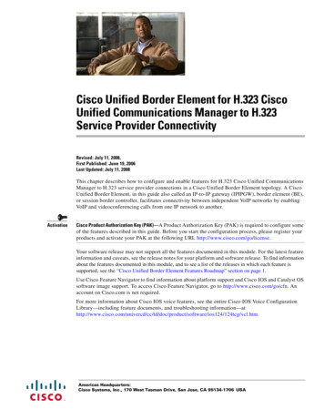
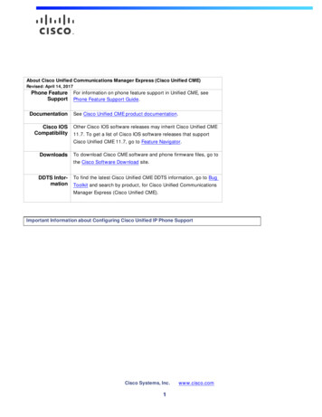
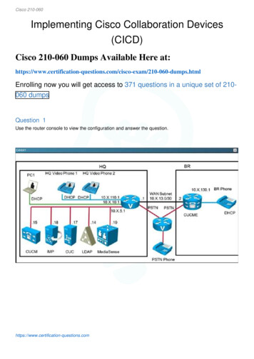
Chapter 41Cisco Unified Border Element (SP Edition)—SPA DSP ServicesInformation About the SPA DSP ServicesTranscoding the SBCSBC transcoding is used for codec translation between two VoIP networks as part of the Data BorderElement (DBE) functions. Figure 41-1 shows how a SPA DSP performs codec transcoding for unifiedSBC and Figure 41-2 shows how a SPA DSP performs codec transcoding for distributed SBC.Figure 41-1SPA DSP Transcoding for Unified SBCDSPsIPG.711G.729IPG.729SRF DBEFigure 41-2IP281961SBE DBE TranscoderSPA DSP Transcoding for Distributed SBCSBEDSPsDBE G.729TranscoderG.729IPH.248SIPRTP281698G.711DBEThe SPA DSP allows the translation of one type of media stream or codec to another type of mediastream that uses different media encoding and decoding technologies. Other translation activitiesinclude: Translation between different codecs Translation between different packetization settings (transrating) DTMF interworkingTranscoding the Distributed SBCTranscoding is inferred from a Session Description Protocol (SDP) that is used to program a call.Programming terminations in the same call containing different codecs implicitly instruct the distributedSBC to perform transcoding.Cisco Unified Border Element (SP Edition) Configuration Guide: Unified ModelOL-19820-1541-3
Chapter 41Cisco Unified Border Element (SP Edition)—SPA DSP ServicesInformation About the SPA DSP ServicesTransrating the Distributed SBCTransrating is inferred from the SDP that is used to program a call. Programming terminations in thesame call with different ptime implicitly instruct the distributed SBC to perform transrating.NoteTransrating is supported only for the different rates using the same codec, not across codecs. Therefore,transrating and transcoding cannot be performed simultaneously.RTP Telephone-Event Codec-to-SIP InterworkingWhen an RTP packet is marked as DTMF using the telephone-event codec, the RTP packet is removedfrom the stream. The DBE sends an H.248 message to the signaling border element (SBE), indicatingthat a DTMF event has occurred, and that the RTP packet should be converted into a SIP DTMF event.The call must meet the following conditions: The telephone-event codec (for RFC 2833) is present in side A of the SDP, but not in side B. The dd/etd event is subscribed for side A, but not for side B.SIP-to-RTP Telephone-Event Codec InterworkingWhen an endpoint generates a SIP signal, the SIP DTMF signals arrive completely out of band. Anendpoint that supports SIP DTMF generates the signals to be sent to the SBE. In turn, the SBE recognizesthat this is a DTMF message and sends an H.248 message to the DBE, indicating that a DTMF tone isrequired to be inserted into the RTP stream. The DBE then inserts the RTP DTMF packets into the audiostream using telephone-event codec.The call must meet the following conditions: The telephone-event codec (for RFC 2833) is present in side B of the SDP, but not in side A. The dd/etd event is subscribed for side B, but not for side A.RTP Telephone-Event Codec-to-RTP In-Band WaveformAfter the RTP packet is marked as DTMF using the telephone-event codec, the RTP packet is removedfrom the stream, and an RTP stream containing the DTMF waveform is sent to the other endpoint.The call must meet the following conditions: The telephone-event codec (for RFC 2833) is present in side A of SDP, but not in side B. The dd/etd event is subscribed for side A and side B.RTP In-Band Waveform-to-RTP Telephone-Event CodecAfter the DTMF is sent as part of the voice waveform, the RTP packets are removed from the stream,and the DBE inserts the a new RTP packet with the payload-type telephone event into the audio stream.The call must meet the following conditions: The telephone-event codec (for RFC 2833) is present in side B of the SDP, but not in side A. The dd/etd event is subscribed for side A and side BCisco Unified Border Element (SP Edition) Configuration Guide: Unified Model41-4OL-19820-15
Chapter 41Cisco Unified Border Element (SP Edition)—SPA DSP ServicesInformation About the SPA DSP ServicesSIP-to-RTP In-Band WaveformAfter an endpoint generates a SIP signal, the SIP DTMF signals arrive completely out of band. Theendpoint that supports SIP DTMF generates the signals to be sent to the SBE. In turn, the SBE recognizesthat this is a DTMF message, and sends an H.248 message to the DBE, indicating that a DTMF tone isrequired to be inserted into the RTP stream. The DBE then inserts a stream containing the DTMFwaveform.The call must meet the following conditions: The telephone-event codec (for RFC 2833) is not present on either side A or side B. The dd/etd event is subscribed for side B.RTP In-Band Waveform-to-SIPWhen the DTMF is sent as part of the voice waveform, the RTP packets are removed from the stream,and the DBE sends an H.248 message to the SBE, indicating that a DTMF event has occurred, and thatthe RTP packets should be converted into a SIP DTMF event.The call must meet the following conditions: The telephone-event codec (for RFC 2833) is not present on either side A or side B. The dd/etd event is subscribed for side A.Call RecoveryFrom Cisco IOS XE Release 3.3S, calls on a partially crashed SPA DSP can be recovered within the calloutage time of 2.5s.When part of a SPA DSP crashes, a crash recovery process runs, and then the RP reprograms the crashedpart of the SPA DSP with all calls that were previously on it. For example, a simple transcoding scenario,a-law to u-law transcoding, can represent up to 129 calls that require reprogramming.Depending on the part of the SPA DSP that crashes, the total recovery time may be longer because itmight have to recover more components and also reprogram more calls. However, the entire media pathoutage time for all the recovered calls is less than 2.5s.In all cases of the SPA DSP call recovery, the call recovery occurs on the same SPA DSP where the callexisted prior to the crash. The calls are not moved to another SPA DSP.The SPA DSP failure call recovery can be disabled or rendered ineffective if the SPA DSP crash dumpsare enabled. It can push the call outage time beyond 2.5s.The show voice dsp group all command indicates when a SPA DSP is undergoing call recovery.Router# show voice dsp group allShow DSP group allDSP groups on slot 0 bay 0:dsp 1:State: UPHA State : DSP HA STATE PENDING1Max signal/voice channel: 43/43Max credits: 645num of sig chnls allocated: 43Transcoding channels allocated: 43Group: FLEX GROUP XCODE, complexity: LOWCisco Unified Border Element (SP Edition) Configuration Guide: Unified ModelOL-19820-1541-5
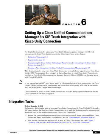
Chapter 41Cisco Unified Border Element (SP Edition)—SPA DSP ServicesInformation About the SPA DSP ServicesShared credits: 0, reserved credits: 645Transcoding channels allocated: 24Credits used (rounded-up): 360NoteThe show voice dsp group all command displays the output HA State : DSP HA STATE PENDING1 onlyduring the recovery process which can be upto a few milliseconds.AMR-WB Transcoding SupportAdaptive Multi-Rate Wideband (AMR-WB) is a patented speech coding standard based on AdaptiveMulti-Rate encoding, using a methodology that is similar to the Algebraic code-excited linear prediction(ACELP). AMR-WB, which was specified by 3GPP, provides improved speech quality due to a widerspeech bandwidth of 50 to 7000Hz compared to narrowband speech coders what are in general optimizedfor Plain old telephone service (POTS) wireline quality of 300 to 3400 Hz.AMR-WB is codified as G.722.2, an ITU-T standard speech codec, formally known as Wideband codingof speech at around 16 kbps using AMR-WB. G.722.2 AMR-WB is the same codec as the 3GPPAMR-WB.AMR-WB operates like AMR with nine different bit rates. The lowest bit rate providing excellent speechquality in a clean environment is 12.65 kbps. Higher bit rates are useful in background noise conditionsand for music. Also, lower bit rates of 6.60 and 8.85 kbps provide reasonable quality, especiallycompared to narrowband codecs.NoteThe AMR-WB feature requires DSP firmware with AMR-WB codec support.Cisco Unified Border Element (SP Edition) Configuration Guide: Unified Model41-6OL-19820-15
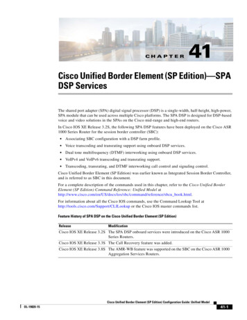
Chapter 41Cisco Unified Border Element (SP Edition)—SPA DSP ServicesConfiguring the SPA DSP Services for SBCTable 41-1shows the relationship between the AMR rate mode and bit-rate.Table 41-1Relationship Between the AMR Rate Mode and Bit-RateRate ModeAMR Bit-Rate (kbps)AMR-WB/G.722.2 Bit-Rate SID1. SID: Silence IndicatorConfiguring the SPA DSP Services for SBCThis section describes the tasks to involved in configuring the SPA DSP services for the SBC: Setting Up a SPA DSP for DSP Farm Services, page 41-7 Configuring a DSP Farm Profile, page 41-8Setting Up a SPA DSP for DSP Farm ServicesUse the following procedure to set up the SPA DSP in the DSP farm mode for the DSP services:SUMMARY STEPS1.configure terminal2.voice-card slot number/subslot number3.dsp services dspfarm4.endCisco Unified Border Element (SP Edition) Configuration Guide: Unified ModelOL-19820-1541-7
Chapter 41Cisco Unified Border Element (SP Edition)—SPA DSP ServicesConfiguring the SPA DSP Services for SBCDETAILED STEPSStep 1Command or ActionPurposeconfigure terminalEnters global configuration mode.Example:Router# configure terminalStep 2voice-card slot number/subslot numberSpecifies the slot number of the voice card and enters thevoice card interface configuration mode.Example:Router(config)# voice-card 0/2Step 3dsp services dspfarmAllows DSP farm services on the SPA DSP voice card.Example:Router(config-voicecard)# dsp services dspfarmStep 4Exits the voice card interface configuration mode.endExample:Router(config-voicecard)# endFor more information about configuring DSP farm services on a SPA DSP, see the “Configuring theCisco DSP SPA for ASR 1000 Series” chapter in the Cisco ASR 1000 Series Aggregation ServicesRouters SIP and SPA Software Configuration Guide at:http://www.cisco.com/en/US/docs/interfaces modules/shared port guring a DSP Farm ProfileUse the following steps to configure a DSP farm profile:SUMMARY STEPS1.configure terminal2.dspfarm profile profile-identifier {conference mtp transcode}3.description profile-description-text4.codec codec-name5.associate application {cube sbc sccp}6.maximum session number7.no shutdown8.endCisco Unified Border Element (SP Edition) Configuration Guide: Unified Model41-8OL-19820-15
Chapter 41Cisco Unified Border Element (SP Edition)—SPA DSP ServicesConfiguring the SPA DSP Services for SBCDETAILED STEPSStep 1Command or ActionPurposeconfigure terminalEnters the global configuration mode.Example:Router# configure terminalStep 2dspfarm profile profile-identifier {conference mtp transcode}Enables the DSP farm service for the specified DSP farmprofile, and enters a DSP farm profile configuration mode.The service options are:Example:Router(config)# dspfarm profile 20 transcode conference—Enables conferencing. mtp—Enables media termination point. transcode—Enables transcoding of information.NoteStep 3In Cisco IOS Release 3.2S, only the transcodeservice is supported.Specifies a description for a defined profile.description arm-profile)# descriptionenables transcodingStep 4Adds codecs or removes the codec from a codec list. Thecodec must be present in the list of codecs that the SBE ishard-coded to recognize.no codec ter(config-dspfarm-profile)#Step smamr-nbg726r32g729br8associate application {cube sbc sccp}profile-description-textAssociates an application to the profile. The applicationsthat can be associated are: cube—Associates the Cisco Unified Border Elementapplication to a defined profile in the DSP farm. sbc—Associates the SBC application to a definedprofile in the DSP farm. sccp—Associates the client control protocolapplication to a defined profile in the DSP farm.Example:Router(config-dspfarm-profile)# associateapplication sbcNoteThe sbc application keyword is available only whena DSP farm profile transcode service is used.Cisco Unified Border Element (SP Edition) Configuration Guide: Unified ModelOL-19820-1541-9
Chapter 41Cisco Unified Border Element (SP Edition)—SPA DSP ServicesConfiguring the Unified SBCStep 6Command or ActionPurposemaximum session numberEstablishes the maximum number of sessions that can beassigned to a defined profile. The maximum number ofsessions is dependent upon the number of SPA DSPs in therouter, and the codecs configured. For a fully populatedCisco ASR 1013 Series Router with 23 SPA DSPs and onlythe G711 codec, the maximum number of sessions would be20769.Example:Router(config-dspfarm-profile)# maximum session300Step 7Enables or disables a DSP farm profile.no shutdownExample:Router(config-dspfarm-profile)# no shutdownStep 8Exits the DSP farm profile.endExample:Router(config-dspfarm-profile)# endConfiguring the Unified SBCThis section explains the various ways in which to configure the SBC for the SPA DSP voice card: Associating the Unified SBC with a DSP Farm Profile, page 41-10 Configuring the Unified SBC to Enable Transcoding, page 41-11 Configuring the Unified SBC to Enable Transrating, page 41-17 Configuring the Unified SBC to Enable SRTP and Transcoding, page 41-22 Configuring the Unified SBC for Inband DTMF Interworking, page 41-28 Configuring the Unified SBC to Support AMR-WB, page 41-33Associating the Unified SBC with a DSP Farm ProfileAssociation of the SBC to the DSP farm profiles is possible only after the corresponding DSP farmprofile is created. Use the associate dspfarm profile command in the global configuration mode.SUMMARY STEPS1.show dspfarm {all dsp profile}2.configure terminal3.sbc sbc-name4.associate dspfarm profile {profile-number all}5.endCisco Unified Border Element (SP Edition) Configuration Guide: Unified Model41-10OL-19820-15
Chapter 41Cisco Unified Border Element (SP Edition)—SPA DSP ServicesConfiguring the Unified SBCDETAILED STEPSStep 1Command or ActionPurposeshow dspfarm {all dsp profileprofile-identifier}Displays the DSP farm configuration information:Example:Router# show dspfarm profile allStep 2 all—Displays the DSP farm global information. dsp—Displays information pertaining to all the DSPs. profile—Displays the DSP farm profiles.Enables the global configuration mode.configure terminalExample:Router# configure terminalStep 3Creates the SBC service on the SBC, and enters the SBCconfiguration mode.sbc sbc-nameExample:Router(config)# sbc mySBCStep 4associate dspfarm profile {profile-number all}Example:Router(config-sbc)# associate dspfarm profile 1Step 5Associates the SBC to a DSP farm profile: profile-number—Specifies the profile number to beassociated. all—Allows the SBC to pick the most appropriate DSPfarm profile from the profiles associated to the SBC forthe transcoding session.Exits the configuration mode.endExample:Router(config-sbc-sbe)# endConfiguring the Unified SBC to Enable TranscodingThis task configures the SBC for enabling the transcoding feature.NoteThe caller and callee commands have been used in this procedure. In some scenarios, the branchcommand can be used as an alternative to the caller and callee command pair. The branch commandhas been introduced in Release 3.5.0. See the ? paranum Configuring Directed Nonlimiting CACPolicies? section on page 7-37 for information about this command.SUMMARY STEPS1.configure terminal2.sbc sbc-name3.sbe4.cac-policy-set policy-set-id5.first-cac-scope scope-nameCisco Unified Border Element (SP Edition) Configuration Guide: Unified ModelOL-19820-1541-11
Chapter 41Cisco Unified Border Element (SP Edition)—SPA DSP ServicesConfiguring the Unified SBC6.first-cac-table table-name7.cac-table table-name8.table-type limit list of limit tables9.entry entry-id10. match-value key11. callee-codec-list list-name12. caller-codec-list list-name13. media police strip reject degrade14. action cac-complete15. complete16. cac-policy-set global cac-policy-num17. codec-list list-name18. codec codec-nam19. exit20. codec-list list-name21. codec codec-nam22. exit23. end24. show sbc sbc-name sbe call-stats global current5minDETAILED STEPSStep 1Command or ActionPurposeconfigure terminalEnables global configuration mode.Example:Router# configure terminalStep 2sbc sbc-nameCreates the SBC service on the SBC, and enters the SBCconfiguration mode.Example:Router(config)# sbc mySBCStep 3Enters the signaling border element (SBE) function mode ofthe SBC.sbeExample:Router(config-sbc)# sbeStep 4cac-policy-set policy-set-idExample:Router(config-sbc-sbe)# cac-policy-set 1Enters the CAC policy set configuration mode within anSBE entity, creating a new policy set, if necessary: policy-set-id—Integer chosen by a user to identify thepolicy set. The range is from 1 to 2147483647.Cisco Unified Border Element (SP Edition) Configuration Guide: Unified Model41-12OL-19820-15
Chapter 41Cisco Unified Border Element (SP Edition)—SPA DSP ServicesConfiguring the Unified SBCStep 5Command or ActionPurposefirst-cac-scope scope-nameConfigures the scope at which limits should be initiallydefined to perform tasks at the admission control stage ofthe policy. Each CAC policy has a scope that can be appliedto it. This CAC policy is applicable on a per call st-cac-scope dst-adjacencyStep 6scope-name has one of the following values:adj-group—Limits for events from members of thesame adjacency group. call—Limits are per single call. category—Limits per category. dst-account—Limits for events sent to the sameaccount. dst-adj-group—Limits for events sent to the sameadjacency group. dst-adjacency—Limits for events sent to the sameadjacency. dst-number—Limits for events that have the sameadjacency number. global—Limits are global and should not be combinedwith any other option. src-account—Limits for events from the same account. src-adj-group—Limits for events from the sameadjacency group. arc-adjacency—Limits for events from the sameadjacency. src-number—Limits for events that have the samesource number.Configures the name of the first policy table to beprocessed. A CAC policy may have many tables configured.To start applying the CAC policy, the first table that is usedmust be defined:first-cac-table #first-cac-table codec-dst-accStep 7 table-name—The admission control table that shouldbe processed first.Enters the CAC table mode for configuration of anadmission control table (creating one, if necessary) withinthe context of an SBE policy set.cac-table # cac-tablecodec-dst-acc table-name—Name of the admission control table.Cisco Unified Border Element (SP Edition) Configuration Guide: Unified ModelOL-19820-1541-13
Chapter 41Cisco Unified Border Element (SP Edition)—SPA DSP ServicesConfiguring the Unified SBCStep 8Command or ActionPurposetable-type limit list of limit tablesConfigures a new CAC Limit table type in which the criteriaused to match the entries must be entered.Example:list of limit tables can be one of the following able-type limit dst-adjacencyStep 9entry entry-idExample: account—Compare the name of the account. adj-group—Compare the name of the adjacencygroup. adjacency—Compare the name of the adjacency. all—No comparison type. All events match this type. call-priority—Compare with call priority. category—Compare the number analysis assignedcategory. dst-account—Compare the name of the destinationaccount. dst-adj-group—Compare the name of the destinationadjacency group. dst-adjacency—Compare the name of the destinationadjacency. dst-prefix—Compare the beginning of the dialed digitstring. event-type—Compare with CAC policy event types. src-account—Compare the name of the sourceaccount. src-adj-group—Compare the name of the sourceadjacency group. src-adjacency—Compare the name of the sourceadjacency. src-prefix—Compare the beginning of the callingnumber string.Enters the CAC table entry mode to modify an entry in anadmission control table. entry-id—Specifies the table try 1Step 10match-value keyConfigures the match value of an entry in a CAC Limit cactable-entry)# match-value navaStep 11callee-codec-list list-nameLists the codecs that the callee leg of a call is allowed to le-entry)# callee-codec-list PCMUCisco Unified Border Element (SP Edition) Configuration Guide: Unified Model41-14OL-19820-15
Chapter 41Cisco Unified Border Element (SP Edition)—SPA DSP ServicesConfiguring the Unified SBCStep 12Command or ActionPurposecaller-codec-list list-nameLists the codecs that the caller leg of a call is allowed to le-entry)# caller-codec-list PCMAStep 13media police strip reject degradeExample:Configures the manner in which the SBC will handle themedia streams that exceed the bandwidth limit for e-entry)# media police stripStep 14When an event matches, the CAC policy is consideredcomplete.action y-cactable-entry)# action cac-completeStep 15Completes the CAC policy set when you have committedthe full y)# completeStep 16Activates the global CAC policy set. The CAC policy setmust be in a complete state before it can be assigned as thedefault policy.cac-policy-set global policy-numExample:Router(config-sbc-sbe)# cac-policy-set global 1Step 17 policy-num—The call policy set number, ranging from1 to 2147483647. The policy set must be in a completestate before it can be assigned as the default policy.Creates a codec list, and enters the Codec list configurationmode.codec-list list-nameExample:Router(config-sbc-sbe)# codec-list PCMUStep 18Adds a codec to a codec list.codec )# codec PCMUStep 19Exits the codec list configuration # exitStep 20Creates a codec list, and enters the Codec list configurationmode.codec-list list-nameExample:Router(config-sbc-sbe)# codec-list PCMAStep 21Adds a codec to a codec list.codec )# codec PCMACisco Unified Border Element (SP Edition) Configuration Guide: Unified ModelOL-19820-1541-15
Chapter 41Cisco Unified Border Element (SP Edition)—SPA DSP ServicesConfiguring the Unified SBCStep 22Command or ActionPurposeexitExits the codec list configuration mode.Example:Router(config-sbc-sbe-codec-list)# exitStep 23Ends the configuration session.endExample:Router(config-sbc-sbe)# endStep 24show sbc sbc-name sbe call-stats globalcurrent5minLists the statistics for all the calls on the specified SBE.Example:Router# show sbc mySBC sbe call-stats globalcurrent5minThe following example shows an output of the show sbc sbe call-stats global current5min commandthat lists the count of the active transcoded and transrated calls.Router# show sbc mySBC sbe call-stats global current5minSBC Service "mySBC"Statistics for the current 5 mins for global countersCall count totals:Total call attempts Total active calls Total active IPv6 calls Total activating calls Total de-activating calls Total active emergency calls Total active e2 emergency calls Total IMS rx active calls Total IMS rx call renegotiation attempts Total SRTP-RTP interworked calls Total active calls not using SRTP Total active transcoded calls Total active transrated calls General call failure counters:Total call setup failures Total active call failures Total failed call attempts Total failed calls due to update failure Total failed calls due to resource failure Total failed calls due to congestion Total failed calls due to media failure Total failed calls due to signaling failure Total failed calls due to IMS rx setup failure Total failed calls due to IMS rx renegotiation failure Total failed calls due to RTP disallowed on call leg Total failed calls due to SRTP disallowed on call leg 0100000000110000000000000Cisco Unified Border Element (SP Edition) Configuration Guide: Unified Model41-16OL-19820-15
Chapter 41Cisco Unified Border Element (SP Edition)—SPA DSP ServicesConfiguring the Unified SBCConfiguring the Unified SBC to Enable TransratingNoteTransrating is supported only for different rates using the same codec, not across codecs. Therefore,transrating and transcoding cannot be performed simultaneously.This section describes how to enable transrating using either of the following methods: Transrating Using the Same Codec Policy, page 41-17 Transrating Using a New Codec Policy, page 41-21Transrating Using the Same Codec PolicyThis task configures the SBC for enabling the transrating using the same codec policy.NoteThe caller and callee commands have been used in this procedure. In some scenarios, the branchcommand can be used as an alternative to the caller and callee command pair. The branch commandhas been introduced in Release 3.5.0. See the ? paranum Configuring Directed Nonlimiting CACPolicies? section on page 7-37 for information about this command.SUMMARY STEPS1.configure terminal2.sbc sbc-name3.sbe4.cac-policy-set policy-set-id5.first-cac-table table-name6.cac-table table-name7.table-type {policy-set limit {list of limit tables}}8.entry entry-id9.cac-scope {list of scope options}10. callee ptime 0-10011. caller ptime 0-10012. media police strip reject degrade13. action cac complete14. complete15. cac-policy-set global cac-poli
SPA module that can be used across multiple Cisco platforms. The SPA DSP is designed for DSP-based voice and video solutions in the SPAs on the Cisco mid-range and high-end routers. In Cisco IOS XE Release 3.2S, the following SPA DSP features have been deployed on the Cisco ASR 1000 Series Router for the session border controller (SBC):