Transcription
AutoCAD 2009 TutorialFirst Level: 2D FundamentalsText byMultiMedia DVD byRandy H. ShihJohn GrangerOregon Institute of TechnologyLane Community CollegeSDCPUBLICATIONSSchroff Development CorporationMULTIMEDIA DVD INSIDE:Included:A video presentationof the tutorial exercisesAdditional video study aidsfor the AutoCAD CertifiedUser Examinationwww.schroff.com
Visit the following websites to learn more about this book:
AutoCAD 2009 Tutorial: 2D FundamentalsCopyrightedMaterialChapter 1AutoCAD FundamentalsCopyrightedMaterialCopyrightedMaterial Create and Save AutoCAD drawing files Use the AutoCAD visual referencecommands Draw, using the LINE and CIRCLEcommands Use the ERASE command Define Positions using the Basic Entrymethods Use the AutoCAD Pan Realtime optionCopyrightedMaterial1-1
1-2AutoCAD 2009 Tutorial: 2D FundamentalsCopyrightedMaterialAutoCAD Certified User Examination Objectives CoverageThis table shows the pages on which the objectives of the Certified User Examination are covered inChapter 1.Section 1: Controlling the Display in DrawingsPrecision.1-4Zoom Extent.1-5Drawing LIMITS .1-5Status Bar .1-10GRID Display .1-10, 1-11PAN Realtime .1-20CopyrightedMaterialCertified User Reference GuideSection 2: Creating Basic DrawingsFormat .1-4Units Setup .1-4LINE command.1-6Coordinates .1-7Interactive Input method .1-8SNAP Option .1-10World space .1-13User coordinate system .1-15World coordinate system .1-15UCS icon Display .1-16TTR, circle .1-16Relative Coordinate .1-17Coordinate systems .1-17Cartesian coordinate system .1-17Absolute coordinates.1-17, 1-18Positions, defining.1-18LINE, Close option .1-19CIRCLE command.1-22TTT, circle .1-22CopyrightedMaterialSection 3: Manipulating ObjectsERASE command .1-13Selection window.1-14CopyrightedMaterial
AutoCAD ning to use a CAD system is similar to learning a new language. It is necessary tobegin with the basic alphabet and learn how to use it correctly and effectively throughpractice. This will require learning some new concepts and skills as well as learning adifferent vocabulary. All CAD systems create designs using basic geometric entities.Many of the constructions used in technical designs are based upon two-dimensionalplanar geometry. The method and number of operations that are required to accomplishthe constructions are different from one system to another.In order to become effective in using a CAD system, we must learn to create geometricentities quickly and accurately. In learning to use a CAD system, lines and circles are thefirst two, and perhaps the most important two, geometric entities that one should masterthe skills of creating and modifying. Straight lines and circles are used in almost alltechnical designs. In examining the different types of planar geometric entities, theimportance of lines and circles becomes obvious. Triangles and polygons are planarfigures bounded by straight lines. Ellipses and splines can be constructed by connectingarcs with different radii. As one gains some experience in creating lines and circles,similar procedures can be applied to create other geometric entities. In this chapter, thedifferent ways of creating lines and circles in AutoCAD 2009 are examined.CopyrightedMaterialStarting Up AutoCAD 20091. Select the AutoCAD 2009 option on the Program menu or select theAutoCAD 2009 icon on the Desktop. Once the program is loaded intomemory, the AutoCAD 2009 drawing screen will appear on the screen.CopyrightedMaterialCopyrightedMaterial
1-4AutoCAD 2009 Tutorial: 2D Fundamentals Note that AutoCAD automatically assigns generic name, Drawing X, as newdrawings are created. In our example, AutoCAD opened the graphics window usingthe default system units and assigned the drawing name yrightedMaterialDrawing Units Setup Every object we construct in a CAD system is measured in units. We shoulddetermine the value of the units within the CAD system before creating the firstgeometric entities.1. Click the Menu Browser, the big button at thetop left corner of the AutoCAD main windowand select:[Format] [Units]CopyrightedMaterial The AutoCAD Menu Browser containsmultiple pull-down menus, where commonlyused AutoCAD commands can be accessed.Note that many of the menu items listed in thepull-down menus can also be accessed throughthe Quick Access toolbar and/or Ribbon panels.
AutoCAD Fundamentals1-5CopyrightedMaterial2. Click on the Length Type option to display the different types of length unitsavailable. Confirm the Length Type is set to Decimal.CopyrightedMaterial3. On your own, examine the other settings that areavailable.4. In the Drawing Units dialog box, set the Length Type to Decimal. This willset the measurement to the default English units, inches.CopyrightedMaterialCopyrightedMaterial5. Set the Precision to two digits after the decimal point as shown in the abovefigure.6. Pick OK to exit the Drawing Units dialog box.
1-6AutoCAD 2009 Tutorial: 2D FundamentalsCopyrightedMaterialDrawing Area Setup Next, we will set up the Drawing Limits; setting the Drawing Limits controls theextents of the display of the grid. It also serves as a visual reference that marks theworking area. It can also be used to prevent construction outside the grid limits andas a plot option that defines an area to be plotted/printed. Note that this setting doesnot limit the region for geometry construction.1. Click the Menu Browser button, and select:[Format] [Drawing Limits]CopyrightedMaterial2. In the command prompt area, near the bottom of the AutoCAD drawingscreen, the message “Reset Model Space Limits: Specify lower left corner or[On/Off] 0.00,0.00 :” is displayed. Press the ENTER key once to accept thedefault coordinates 0.00,0.00 .CopyrightedMaterial3. In the command prompt area, the message “Specify upper right corner 12.00,9.00 :” is displayed. Press the ENTER key again to accept the defaultcoordinates 12.00,9.00 .CopyrightedMaterial4. On your own, move the graphic cursor near the upper-right comer inside thedrawing area and note that the drawing area is unchanged. (The DrawingLimits command is used to set the drawing area, but the display will not beadjusted until a display command is used.)
AutoCAD Fundamentals1-7CopyrightedMaterial5. Click the Menu Browser button, and select:[View] [Zoom] [All] The Zoom All command will adjust the displayso that all objects in the drawing are displayed tobe as large as possible. If no objects areconstructed, the Drawing Limits are used to adjustthe current viewport.6. Move the graphic cursor near the upper-rightcomer inside the drawing area and note that thedisplay area is updated.CopyrightedMaterialUsing the InfoCenter to get more information Prior to creating geometric objects, let’s examine the usage of the InfoCenteroption to obtain some help on the subject.1. Type Draw lines in the InfoCenter input boxto search for any Draw lines relatedinformation.2. Click Draw Geometric Objects in theAutoCAD Help list as shown.CopyrightedMaterial3. In the AutoCAD 2009 User’s Guide, generalinformation regarding the construction ofgeometric objects is described.4. Click Draw Linear Objects to get moreinformation on how to construct LinearObjects.CopyrightedMaterial5. On your own, click Draw Lines and thenLine to view the description of the AutoCADLine command. On your own, read through the descriptionslisted in Concept, Procedure and QuickReference.
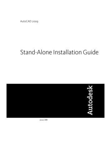
AutoCAD 2009 Tutorial: 2D Fundamentals1-8CopyrightedMaterialDrawing lines with the LINE command1. Move the graphics cursor to the first iconin the Draw panel. This icon is the Lineicon. Note that a brief description of theLine command appears next to the cursor.2. Select the icon by clicking once with theleft-mouse-button, which will activatethe Line command.CopyrightedMaterial3. In the command prompt area, near the bottom of the AutoCAD drawingscreen, the message “ line Specify first point:” is displayed. AutoCADexpects us to identify the starting location of a straight line. Move the graphicscursor inside the graphics window and watch the display of the coordinates ofthe graphics cursor at the bottom of the AutoCAD drawing screen. The threenumbers represent the location of the cursor in the X, Y, and Z directions. Wecan treat the graphics window as if it was a piece of paper and we are usingthe graphics cursor as if it were a pencil with which to draw.CopyrightedMaterialCoordinates of the graphicscursor.5321 We will create a freehand sketch of a fivepoint star using the Line command. Do notbe overly concerned with the actual size orthe accuracy of your freehand sketch. Thisexercise is to give you a feel for theAutoCAD 2009 user interface.CopyrightedMaterial4
AutoCAD Fundamentals1-9CopyrightedMaterial6. We will start at a location about one-thirdfrom the bottom of the graphics window.Left-click once to position the startingpoint of our first line. This will be point 1of our sketch. Next move the cursorupward and toward the right side of point1. Notice the rubber-band line that followsthe graphics cursor in the graphicswindow. Left-click again (point 2) and wehave created the first line of our sketch.CopyrightedMaterial7. Move the cursor to the left of point 2 andcreate a horizontal line about the samelength as the first line on the screen.532CopyrightedMaterial8. Repeat the above steps and completethe freehand sketch by adding threemore lines (from point 3 to point 4,point 4 to point 5, and then connect topoint 5 back to point 1).149. Notice that the Line command remains activated even afterwe connected the last segment of the line to the startingpoint (point 1) of our sketch. Inside the graphics window,click once with the right-mouse-button and a popup menuappears on the screen.CopyrightedMaterial10. Select Enter with the left-mouse-button to end the Linecommand. (This is equivalent to hitting the [ENTER] keyon the keyboard.)11. Move the cursor near point 2 and point 3, and estimate thelength of the horizontal line by watching the displayedcoordinates for each point.
1-10AutoCAD 2009 Tutorial: 2D FundamentalsCopyrightedMaterialVisual referenceThe method we just used to create the freehand sketch is known as the interactivemethod, where we use the cursor to specify locations on the screen. This method isperhaps the fastest way to specify locations on the screen. However, it is rather difficultto try to create a line of a specific length by watching the displayed coordinates. It wouldbe helpful to know what one inch or one meter looks like on the screen while we arecreating entities. AutoCAD 2009 provides us with many tools to aid the construction ofour designs. For example, the GRID and SNAP options can be used to get a visualreference as to the size of objects and learn to restrict the movement of the cursor to a setincrement on the screen.The GRID and SNAP options can be turned ON or OFF through the Status Bar. TheStatus Bar area is located at the bottom left of the AutoCAD drawing screen, next to thecursor coordinates.CopyrightedMaterialOption ButtonsThe first button in the Status Bar is the SNAP option and the second button is the GRIDDISPLAY option. Note that the buttons in the Status Bar area serve two functions: (1) thestatus of the specific option, and (2) as toggle switches that can be used to turn thesespecial options ON and OFF. When the corresponding button is highlighted, the specificoption is turned ON. Using the buttons is a quick and easy way to make changes to thesedrawing aid options. Another aspect of the buttons in the Status Bar is these options canbe switched on and off in the middle of another command.CopyrightedMaterialCopyrightedMaterial
AutoCAD Fundamentals1-11CopyrightedMaterialGRID ON1. Left-click the GRID button in the Status Bar to turn ON the GRID DISPLAYoption. (Notice in the command prompt area, the message “ Grid on ” is alsodisplayed.)CopyrightedMaterial2. Move the cursor inside the graphics window, and estimate the distance in betweenthe grid points by watching the coordinates display at the bottom of the screen. The GRID option creates a pattern of dots that extends over an area on the screen.Using the grid is similar to placing a sheet of grid paper u
1-10 AutoCAD 2009 Tutorial: 2D Fundamentals Visual reference The method we just used to create the freehand sketch is known as the interactive method, where we use the cursor to specify locations on the screen. This method is perhaps the fastest way to specify locations on the screen. However, it is rather difficult to try to create a line of a specific length by watching the displayed .