Transcription
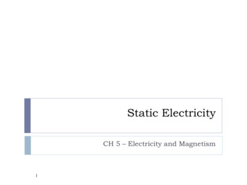
Tutorial #2: Linear-Static Analysis.In this tutorial you will analyze two simple structures: A beam and aflat plate. In your homework you will be asked to compare your FEAsolutions to theoretical results.BEAMS!Part 1.Structural Analysis: Simple GeometryI.Simply supported beam - Surface LoadA. Objective: This problem will familiarize you with the beam finite elementsyou are now learning in class. By comparing the ANSYS solution withsimple beam theory, you will be able to understand the accuracy of yourmodel.1. A schematic of a statically determinate beam with distributed load isshown below.cross section:q 10 kN/mbhb 2 cmh 4 cmL 1mE 200 Gpa 2 x 10⁸ kPa2. We will use the GUI to solve this problem. Follow along. The hollowboxes are provided for you to check off when you have completed thesteps listed a), b), etc. in case you have to stop in the middle. Bulleted,italicized text contains details about the actions.3. Preprocessing Choose the preprocessor from the ANSYS main menu Define the element type:ME309: Finite Element Analysis in Mechanical Design1
a) element type add/edit/delete add The box on the left lists the general element categories,and the subheadings are lists of the element type. Thecategory gives the element type a unique prefix.b) Choose Beam A list of element types for beams should appear in the rightboxc) Choose 2D elastic 3 and click OK. The three is the unique suffix for this element type. Youhave now specified that you will be using the ANSYSelement Beam3, and it will be referred to as element type 1in your model.d) Click Close To find out more about this element, consult the online manual.a) In the ANSYS Input window type, “Help, Beam3” This will usually be more than enough information. If not,you should consult the Theory Manual. Define material properties:a) material properties Material Models b)A two part box will open. The left part indicates you aredefining Material Model 1. In the right part double click:Structural Linear Elastic Isotropic.”In the first box labeled EX input 2e11 and in the second boxlabeled PRXY input 0.35, click OK. Close the window. This creates an isotropic material and assigns it thenumber 1. For this simple analysis, the only elastic constants thatneed to be defined are Young’s modulus and Poisson’sratio. You’re responsible for keeping track of units sinceANSYS is “unitless” Young’s modulus is in N/m2 or Pa.ME309: Finite Element Analysis in Mechanical Design2
Create a set of real constants for the cross-sectiona) real constants add make sure the correct element type is shownb) OK type the following in the correct boxesc) area 8e-4, Izz 1.067e-7, height .04 and click OK.d) Click Close Again, you’re responsible for keeping track of units. Thesehave been entered in meters. Create nodesa) Modeling - create nodes in active cs and enter the following node numbers and coordinates selecting apply will execute the command and query theuser for more inputb) Node 1 is at 0,0c) Applyd) Node 2 is at .5,0e) Apply f)selecting OK will exit the node query and apply the currententryNode 3 is at 1,0 Create elementsa) Create elements auto numbered thru nodes ME309: Finite Element Analysis in Mechanical Design3
You can either pick on the nodes or enter the nodenumbers in the ANSYS input box.b) Pick node 1 then node 2c) Applyd) Pick 2 then 3e) OK, (you have created a 2-element model of the beam) You can plot the elements if they disappear.a) Utility Menu: plot elements Also under plot controls, you can opt to see the boundaryconditions and loads that you are creating.a) Utility Menu: plot controls symbols All Applied BCs OK Now apply a set of boundary conditionsThe Loads menu is in both the Preprocessor menu and theSolutions menu. They are the same. From the Preprocessormenu, first you need to pick the analysis type:a) Loads new analysis analysis type staticb) loads define loads apply structural displacement on nodes c) pick node 1d) apply A window will pop up asking you for the displacemente) choose ux and uy, enter the value 0f)applyg) Pick node 3 this timeh) apply If you click on ux, the highlighting should go away leavingthe highlighting on uy.ME309: Finite Element Analysis in Mechanical Design4
i)Select only uy and enter the value 0j)OKk) Boundary conditions “tie down” the structure at points. It is veryimportant to tie the structure down, otherwise you’ll get zerostress everywhere, large deflections and an invalid solution ingeneral. The only exception is in a modal analysis, where youcan run the analysis “free-free”, that is, unconstrained. Apply the surface loada) loads define loads apply Structural pressure onbeams pick allb) enter the value 10000 in the box for node I (ANSYS willautomatically set the load for node J assuming a uniformpressure load) The load is in N/m, thus we are using a fully consistent setof units – N, m, and Pa. ANSYS does not keep track of theunits for you so beware! You should see the pressure loading graphically since youturned on the boundary conditions earlier.c) Click OKThe next command is very important to consider each time before you run ananalysis. This is because during modeling you may have unselected certainsections of your model and if you don’t reselect them into the “active” set ofentities the analysis will consider only part of your model. Do this before theSOLUTION phase each time you run an analysis! Select all of the nodes (go to the Utility Menu)a) Select everythingb) OK You just selected all of your nodes and put them into the“active set”, in other words, the set that all futurecommands will act on (until you select another set). SAVE DB (from the ANSYS Toolbar)ME309: Finite Element Analysis in Mechanical Design5
Finish (ANSYS Main Menu, at the bottom)a) This takes you out of the preprocessor and cleans up thewindows4. Solution phase Select Solution from the ANSYS main menu.a) Solve - current LSb) OK Close the Information Window that says “solution is done”5. Post-processing Select general post-processor from the ANSYS main menu. Read in the resultsa) Read results - first set This tells ANSYS which results set you want to work with.For this analysis you only have one set. Plot the resultsa) Utility menu: Plot results deformed shape OK this plots the deformed shape. Looking at the deformed shape always gives a first checkto see if the loads, boundary conditions, etc. were appliedcorrectly. If the shape does not make physical sense,examining this plot first will save time and paper. You can obtain a hardcopy of the plot in many ways. Themost popular way is to specify that you will be plotting theabove results to a postscript file instead of the X11, andthen print the file. This file can then be printed as follows:b) Select PlotCtrls Hard copy To file and giving the filenamethen hit OK This basically dumps the graphics window image into apostscript file.ME309: Finite Element Analysis in Mechanical Design6
c) You can view your postscript file before you print by usingGhostView, type ghostview filename at a UNIX prompt or usethe pull-down menu with your left mouse button. You may haveto play with the color of the background to get good contrast onyour printouts. For example try; PlotCtrls Style Background Textured Background Plastic – ivory. Tryother backgrounds.d) Printing is accomplished byClicking Print All in ghostview and type in lpr -Pprintername(the printernames are sweet2 and sweet5) but the easiest is tolaunch mozilla firefox and email the file to yourself. NOTE: epsfiles can be inserted into a word document using insert picture. Get a list of nodal displacements (General Postprocessor)a) List results nodal solution Displacement vector sum OKb) Print it outc) Close Then obtain a list of element stressesa) List results element solution Element Results OKLineElementResults You can save these files to another location or print the filedirectly using the pull-down menus. What’s EPELBYT? SBYB? Go to the online manual andlook up BEAM3 again, it’s all there. Close List the reaction forcesa) List Results Reaction Solu All items OK Model Check: It is good to verify that your reaction loads atthe end constraints equal your applied load. Go to Part VIII to see what should be turned in with yourhomework.ME309: Finite Element Analysis in Mechanical Design7
II. Simply-supported Beam – Surface Load (Again!)A. Model the beam with only one element and repeat the above analysis.B. You can solve this problem by editing the model generated previously.1. To do this, remember to start at the Preprocessor. To remove elements usea) Modeling delete elements pick allb) Modeling delete nodes pick all You just removed the nodes, elements, and the surfaceload. You could have kept nodes 1 and 3.c) Now create only nodes 1 and 3 and put one element betweenthem. Your element type and material are still active, howeveryou must re-apply the constraints and load.2. Review the results: Is this analysis useful? Is it correct? It is just ascorrect as the first analysis, but you only have nodes at the end of thebeam, so you lose the information throughout the beam. You can getANSYS to output results throughout the beam even if there are nonodes – look at the beam3 description in the help file to do it.III. Simply-supported Beam – Surface Load (Again!!)A. Do the same analysis as above, but use 4 nodes and three elements. Create nodes at the following locations: (0,0), (.35,0),(.65,0), (1,0).IV. Simply-supported Beam - Point LoadA.Consider the beam shown below with a point load applied at the mid-span:B. You can solve this problem by editing the model generated previously.1. To do this, remember to start at the Preprocessor. Re-model the beam with 2 elements and the same simplysupported constraintsP 10 kNL 1mL/2L/2ME309: Finite Element Analysis in Mechanical Design8
Then to apply the nodal load usea) loads define loadsforce/moment on nodes V. apply structural Pick the center node. (Fy -10,000) Then do the sameanalysis steps as before.Indeterminate (cantilever) Beam - Surface LoadA. Consider the beam shown below:q 10 kN/mL 1mB. Do the same two element analysis.C. Notice that you should change the boundary conditions at the left end toaccount for the fact that this node cannot rotate or translate, i.e. it’s fixed.VI. Analytical SolutionsA. To find analytical solutions for these models, refer to your undergraduatestructural mechanics book or to Mechanics of Materials by Gere &Timoshenko on reserve in the engineering library.VII. Edit the log filesA. Open the ANSYS .log file and notice your commands. You can edit outerrors and save this file for future reference to read parts of it into ANSYS.ME309: Finite Element Analysis in Mechanical Design9
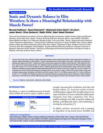
Part 2. Structural Analysis: Using 1/4 SymmetryI.Hole in a square plateA.Objective: With this problem you will be introduced to the use of symmetryand to the strengths and weaknesses of the automesher, while performinga stress analysis on a common engineering model.B. The following GUI guided section will develop the simple model by directgeneration.C. Commands that have been explained in Part 1 (i.e. defining element typeplacing nodes, etc.), are not given the same amount of detail as before.Instead, more emphasis is placed on new commands.1. Consider a 0.3 m square steel plate of thickness 2.5 cm with a centrallylocated circular hole of 1.3 cm radius as shown below. It is subjectedto a pressure on either side of 7 MPa as shown by p on the figure.Young’s ModulusPoisson’s ratioPlate thicknessE 2.1 x 10¹¹ N/m2ν 0.27t 2.5 cmYpX0.3 mRadius 1.3 cmp 7 MPa0.3 m Change the name of the analysis either by restarting ANSYS orsimply go to the utility menu:File change jobnameME309: Finite Element Analysis in Mechanical Design10
Declare element type 1 to be Solid Quad 4 node 42, but beforeyou click OK, click on the Help button in that window. Double clickon the “Pictorial Summary” and then find the Plane42 element.Click on it to find out more about the plane42 element. Or type“Help, Plane42” in the ANSYS Input command line. Set the isotropic Young's modulus of material type 1 to be 2.1e11and set the Poisson's ratio (NUXY) of material type 1 to be 0.27. Watch out for units again. Modulus of elasticity here isconsidered to be units of N/m2 Specify a state of plane stressa) Element type Add/edit/delete Options K3 PlaneStress with thickness This allows you to put a 2-D pressure load rather than aline load on the end of the plate. ANSYS calls theseelement options “keyopts”, which stands for key options. Define the real constant, thickness to be 0.025 Watch out for units. Thickness here is in meters. Place node 1 at .013,0 Place node 13 at 0, .013 Activate cylindrical coordinate system to create some nodes on anarc between nodes 1 and 13. Go to the Utility Menu at the top:a) WorkPlane Change active CS to Global cylindrical Now fill in nodes between nodes 1 and 13a) Modeling Create Nodes Fill between nds pick 1and 13b) OKc) Then choose the starting node number to be 2 and the numberof nodes to fill to be 11 and the increment to be 1.d) OK This tells ANSYS to fill in the space between points 1 and13 with 11 nodes starting with node number 2.ME309: Finite Element Analysis in Mechanical Design11
Cylindrical coordinates can be very useful in modelcreation. Don’t forget to re-activate the Cartesian coordinate systema) WorkPlane Change active CS Global Cartesian You might want to occasionally see what coord. sys. is active atany given time – go to the Utility Menua) List Status Global Status This shows you all of your current modeling settings. Scrolldown until you see “Active coordinate system”. Now place node 157 at .15,0 Node 163 at .15,.15 And node 169
ME309: Finite Element Analysis in Mechanical Design 1 Tutorial #2: Linear-Static Analysis. BEAMS! Part 1.Structural Analysis: Simple Geometry I. Simply supported beam - Surface Load


![Unreal Engine 4 Tutorial Blueprint Tutorial [1] Basic .](/img/5/ue4-blueprints-tutorial-2018.jpg)