Transcription
NO:ISSUED:73119Sep. 20, 2004HOSHIZAKISTACKABLE CRESCENT H3KM-1300SWH3KM-1300SRH3SERVICE MANUAL
IMPORTANTOnly qualified service technicians should attempt to service or maintain thisicemaker. No service or maintenance should be undertaken until the technicianhas thoroughly read this Service Manual.HOSHIZAKI provides this manual primarily to assist qualified service technicians in theservice and maintenance of the icemaker.Should the reader have any questions or concerns which have not been satisfactorilyaddressed, please call or write to the HOSHIZAKI Technical Support Department forassistance.HOSHIZAKI AMERICA, INC.618 Highway 74 SouthPeachtree City, GA 30269Attn: HOSHIZAKI Technical Support DepartmentPhone:Fax:NOTE:1-800-233-1940 Technical Service(770) 487-2331(770) 487-3360To expedite assistance, all correspondence/communication MUST include thefollowing information: Model Number Serial Number Complete and detailed explanation of the problem2
Please review this manual. It should be read carefully before the icemaker is serviced ormaintenance operations are performed. Only qualified service technicians should service andmaintain the icemaker. This manual should be made available to the technician prior to service ormaintenance.CONTENTSI. Specifications . 51. Icemaker . 5KM-1300SAH . 5KM-1300SWH . 6KM-1300SRH . 7KM-1300SAH3 . 8KM-1300SWH3 . 9KM-1300SRH3 . 102. Condensing Unit. 11URC-12F . 11II. General Information . 131. Construction . 13[a] KM-1300SAH, KM-1300SAH3 . 13[b] KM-1300SWH, KM-1300SWH3 . 14[c] KM-1300SRH, KM-1300SRH3 . 152. Controller Board . 16[a] Solid-State Control . 16[b] Controller Board . 16[c] Sequence . 20[d] Controls and Adjustments . 23[e] Checking the Controller Board . 26III. Technical Information . 281. Water Circuit and Refrigerant Circuit. 28[a] KM-1300SAH, KM-1300SAH3 . 28[b] KM-1300SWH, KM-1300SWH3 . 29[c] KM-1300SRH, KM-1300SRH3 . 302. Wiring Diagrams . 31[a] KM-1300SAH, KM-1300SWH . 31[b] KM-1300SRH . 32[c] KM-1300SAH3, KM-1300SWH3. 33[d] KM-1300SRH3 . 343. Timing Chart . 354. Performance Data . 37[a] KM-1300SAH . 37[b] KM-1300SWH . 38[c] KM-1300SRH . 39[d] KM-1300SAH3 . 40[e] KM-1300SWH3 . 41[f] KM-1300SRH3 . 423
IV. Service Diagnosis . 431. No Ice Production . 432. Evaporator is Frozen Up . 473. Low Ice Production . 484. Abnormal Ice . 485. Other . 48V. Removal and Replacement of Components . 491. Service for Refrigerant Lines . 49[a] Refrigerant Recovery . 49[b] Evacuation and Recharge [R-404A] . 492. Brazing . 503. Removal and Replacement of Compressor . 514. Removal and Replacement of Drier . 525. Removal and Replacement of Expansion Valve . 536. Removal and Replacement of Hot Gas Valve and Line Valve . 547. Removal and Replacement of Evaporator . 558. Removal and Replacement of Water Regulating Valve - Water-Cooled Model Only . 569. Adjustment of Water Regulating Valve - Water-Cooled Model Only . 5710. Removal and Replacement of Condensing Pressure Regulator (C.P.R.) Remote Air-Cooled Model Only . 5811. Removal and Replacement of Thermistor . 5912. Removal and Replacement of Fan Motor . 6013. Removal and Replacement of Water Valve . 6114. Removal and Replacement of Pump Motor . 6115. Removal and Replacement of Spray Tubes. 62VI. Maintenance and Cleaning Instructions . 631. Preparing the Icemaker for Long Storage . 632. Cleaning and Sanitizing Procedures . 65[a] Cleaning Procedure . 66[b] Sanitizing Procedure - Following Cleaning Procedure . 683. Maintenance . 694
I. Specifications1. IcemakerKM-1300SAHAC SUPPLY VOLTAGEAMPERAGEMINIMUM CIRCUIT AMPACITYMAXIMUM FUSE SIZEAPPROXIMATE ICE PRODUCTIONPER 24 HR.lbs./day ( kg/day )Reference without *marks208-230/60/1 (3 wire with neutral for 115V)12.6 A ( 5 Min. Freeze AT 104 F / WT 80 F)20 A20 AAmbientWATER TEMP. ( F)Temp.( F)50709070*1283 (582)1242 (563)1135 (515)801252 (568)1188 (539)1053 (478)901242 (563)*1143 (518)1017 (461)1001203 (546)1114 (505)902 (409)SHAPE OF ICECrescent CubeICE PRODUCTION PER CYCLE30.1 lbs. (13.7 kg) 1440 pcs.APPROXIMATE STORAGE CAPACITYN/AELECTRIC & WATER CONSUMPTION90/70 F70/50 FELECTRIC W (kWH/100 lbs.)2334 (4.9)2180 (0.0)WATER gal./24HR (gal./100 lbs.)327 (28.6)697 (54.3)EXTERIOR DIMENSIONS (WxDxH)48" x 27 3/8" x 27 3/8" (1219 x 695 x 695 mm)EXTERIOR FINISHStainless Steel, Galvanized Steel (Rear)WEIGHTNet 275 lbs. ( 125 kg ), Shipping 315 lbs. ( 143 kg )CONNECTIONS - ELECTRICPermanent - Connection- WATER SUPPLYInlet1/2" FPT- DRAINOutlet3/4" FPT- CONDENSATE DRAIN3/8" OD PipeCUBE CONTROL SYSTEMFloat SwitchHARVESTING CONTROL SYSTEMHot Gas and Water, Thermistor and TimerICE MAKING WATER CONTROLTimer Controlled. Overflow PipeCOOLING WATER CONTROLN/ABIN CONTROL SYSTEMThermostatCOMPRESSORHermetic,Model CS14K6E-PFV-237CONDENSERAir-cooled, Fin and Tube TypeEVAPORATORVertical type, Stainless Steel and CopperREFRIGERANT CONTROLThermostatic Expansion ValveREFRIGERANT CHARGER-404A,3 lb. 14 oz. ( 1750 g )DESIGN PRESSUREHigh 467 PSIG, Low 230 PSIGP.C. BOARD CIRCUIT PROTECTIONHigh Voltage Cut-out ( Internal )COMPRESSOR PROTECTIONAuto-reset Overload Protector ( Internal )REFRIGERANT CIRCUIT PROTECTIONAuto-reset High Pressure Control SwitchLOW WATER PROTECTIONFloat SwitchACCESSORIES -SUPPLIEDN/A-REQUIREDIce Storage BinOPERATING CONDITIONSVOLTAGE RANGE187 - 253 VAMBIENT TEMP.45 -100 FWATER SUPPLY TEMP.45 - 90 FWATER SUPPLY PRESSURE10 - 113 PSIGWe reserve the right to make changes in specifications and design without prior notice.5
KM-1300SWHAC SUPPLY VOLTAGEAMPERAGEMINIMUM CIRCUIT AMPACITYMAXIMUM FUSE SIZEAPPROXIMATE ICE PRODUCTIONPER 24 HR.lbs./day ( kg/day )Reference without *marksSHAPE OF ICEICE PRODUCTION PER CYCLEAPPROXIMATE STORAGE CAPACITYELECTRIC & WATER CONSUMPTIONELECTRIC W (kWH/100 lbs.)POTABLE WATERWATER COOLED CONDENSERgal./24HR (gal./100 lbs.)EXTERIOR DIMENSIONS (WxDxH)EXTERIOR FINISHWEIGHTCONNECTIONS - ELECTRIC- WATER SUPPLY- DRAINCUBE CONTROL SYSTEMHARVESTING CONTROL SYSTEMICE MAKING WATER CONTROLCOOLING WATER CONTROLBIN CONTROL SYSTEMCOMPRESSORCONDENSEREVAPORATORREFRIGERANT CONTROLREFRIGERANT CHARGEDESIGN PRESSUREP.C. BOARD CIRCUIT PROTECTIONCOMPRESSOR PROTECTIONREFRIGERANT CIRCUIT PROTECTIONLOW WATER PROTECTIONACCESSORIES -SUPPLIED-REQUIREDOPERATING CONDITIONS208-230/60/1 (3 wire with neutral for 115V)9.7 A ( 5 Min. Freeze AT 104 F / WT 80 F)20 A20 AAmbientWATER TEMP. ( F)Temp.( F)50709070*1284 (582)1282 (582)1208 (548)801283 (582)1280 (581)1166 (529)901282 (582)*1278 (580)1180 (535)1001243 (564)1255 (569)1089 (494)Crescent Cube30.1 lbs. (13.7 kg) 1440 pcs.N/A90/70 F70/50 F2130 (4.0)2033 (3.8)282 (22.1)512 (39.9)920 (72)668 (52)48" x 27-3/8" x 27 3/8" (1219 x 695 x 695 mm)Stainless Steel, Galvanized Steel (Rear)Net 265 lbs. ( 120 kg ), Shipping 315 lbs. (143 kg)Permanent - ConnectionInlet1/2" FPTCond. Inlet1/2" FPTOutlet3/4" FPTCond. Outlet 3/8" FPT3/8" OD PipeFloat SwitchHot Gas and Water, Thermistor and TimerTimer Controlled. Overflow PipeWater RegulatorThermostatHermetic, Model CS14K6E-PFV-237Water-cooled, Tube in tube typeVertical type, Stainless Steel and CopperThermostatic Expansion ValveR-404A,2 lb. 2 oz. ( 950 g )High 427 PSIG, Low 230 PSIGHigh Voltage Cut-out ( Internal )Auto-reset Overload Protector ( Internal )Auto-reset High Pressure Control SwitchFloat SwitchN/AIce Storage BinVOLTAGE RANGE187 - 253 VAMBIENT TEMP.45 -100 FWATER SUPPLY TEMP.45 - 90 FWATER SUPPLY PRESSURE10 - 113 PSIGWe reserve the right to make changes in specifications and design without prior notice.6
KM-1300SRHAC SUPPLY VOLTAGEAMPERAGEMINIMUM CIRCUIT AMPACITYMAXIMUM FUSE SIZEAPPROXIMATE ICE PRODUCTIONPER 24 HR.lbs./day ( kg/day )Reference without *marks208-230/60/1 (3 wire with neutral for 115V)14.5 A ( 5 Min. Freeze AT 104 F / WT 80 F)20 A20 AAmbientWATER TEMP. ( F)Temp.( F)50709070*1296 (588)1257 (570)1173 (532)801266 (574)1206 (547)1105 (501)901257 (570)*1163 (528)1068 (484)1001230 (558)1141 (517)980 (445)SHAPE OF ICECrescent CubeICE PRODUCTION PER CYCLE30.1 lbs. (13.7 kg) 1440 pcs.APPROXIMATE STORAGE CAPACITYN/AELECTRIC & WATER CONSUMPTION90/70 F70/50 FELECTRIC W (kWH/100 lbs.)2326 (4.8)2300 (0.0)WATER gal./24HR (gal./100 lbs.)355 (30.5)772 (59.6)EXTERIOR DIMENSIONS (WxDxH)48" x 27 3/8" x 27 3/8" (1219 x 695 x 695 mm)EXTERIOR FINISHStainless Steel, Galvanized Steel (Rear)WEIGHTNet 255 lbs. ( 116 kg ), Shipping 315 lbs. ( 143 kg )CONNECTIONS - ELECTRICPermanent - Connection- WATER SUPPLYInlet1/2" FPT- DRAINOutlet3/4" FPT- CONDENSATE DRAIN3/8" OD PipeCUBE CONTROL SYSTEMFloat SwitchHARVESTING CONTROL SYSTEMHot Gas and Water, Thermistor and TimerICE MAKING WATER CONTROLTimer Controlled. Overflow PipeCOOLING WATER CONTROLN/ABIN CONTROL SYSTEMThermostatCOMPRESSORHermetic,Model CS14K6E-PFV-279CONDENSERAir-cooled remote, Condenser Unit URC-12FrecommendedEVAPORATORVertical type, Stainless Steel and CopperREFRIGERANT CONTROLThermostatic Expansion ValveCondensing Pressure Regulator on URC-12FREFRIGERANT CHARGER-404A,11 lbs. 7 oz. ( 5200 g )( Icemaker 7 lbs.; Cond. Unit 4 lbs. 7 oz. )DESIGN PRESSUREHigh 467 PSIG, Low 230 PSIGP.C. BOARD CIRCUIT PROTECTIONHigh Voltage Cut-out ( Internal )COMPRESSOR PROTECTIONAuto-reset Overload Protector ( Internal )REFRIGERANT CIRCUIT PROTECTIONAuto-reset High Pressure Control SwitchLOW WATER PROTECTIONFloat SwitchACCESSORIES -SUPPLIEDN/A-REQUIREDIce Storage Bin, Remote Condenser UnitOPERATING CONDITIONSVOLTAGE RANGE187 - 253 VAMBIENT TEMP.45 -100 FWATER SUPPLY TEMP.45 - 90 FWATER SUPPLY PRESSURE10 - 113 PSIGWe reserve the right to make changes in specifications and design without prior notice.7
KM-1300SAH3AC SUPPLY VOLTAGEAMPERAGEMINIMUM CIRCUIT AMPACITYMAXIMUM FUSE SIZEAPPROXIMATE ICE PRODUCTIONPER 24 HR.lbs./day ( kg/day )Reference without *marks208-230/60/37.8 A ( 5 Min. Freeze AT 104 F / WT 80 F)20 A20 AAmbientWATER TEMP. ( F)Temp.( F)50709070*1320 (599)1265 (574)1153 (523)801278 (580)1192 (541)1060 (481)901265 (574)*1132 (513)1006 (456)1001230 (558)1102 (500)890 (404)SHAPE OF ICECrescent CubeICE PRODUCTION PER CYCLE30.1 lbs. (13.7 kg) 1440 pcs.APPROXIMATE STORAGE CAPACITYN/AELECTRIC & WATER CONSUMPTION90/70 F70/50 FELECTRIC W (kWH/100 lbs.)2311 (4.9)2150 (0.0)WATER gal./24HR (gal./100 lbs.)267 (23.6)632 (47.9)EXTERIOR DIMENSIONS (WxDxH)48" x 27 3/8" x 27 3/8" (1219 x 695 x 695 mm)EXTERIOR FINISHStainless Steel, Galvanized Steel (Rear)WEIGHTNet 275 lbs. ( 125 kg ), Shipping 315 lbs. ( 143 kg )CONNECTIONS - ELECTRICPermanent - Connection- WATER SUPPLYInlet1/2" FPT- DRAINOutlet3/4" FPT- CONDENSATE DRAIN3/8" OD PipeCUBE CONTROL SYSTEMFloat SwitchHARVESTING CONTROL SYSTEMHot Gas and Water, Thermistor and TimerICE MAKING WATER CONTROLTimer Controlled. Overflow PipeCOOLING WATER CONTROLN/ABIN CONTROL SYSTEMThermostatCOMPRESSORHermetic,Model CS14K6E-TF5-237CONDENSERAir-cooled, Fin and Tube TypeEVAPORATORVertical type, Stainless Steel and CopperREFRIGERANT CONTROLThermostatic Expansion ValveREFRIGERANT CHARGER-404A,3 lb. 14 oz. ( 1750 g )DESIGN PRESSUREHigh 467 PSIG, Low 230 PSIGP.C. BOARD CIRCUIT PROTECTIONHigh Voltage Cut-out ( Internal )COMPRESSOR PROTECTIONAuto-reset Overload Protector ( Internal )REFRIGERANT CIRCUIT PROTECTIONAuto-reset High Pressure Control SwitchLOW WATER PROTECTIONFloat SwitchACCESSORIES -SUPPLIEDN/A-REQUIREDIce Storage BinOPERATING CONDITIONSVOLTAGE RANGE187 - 253 VAMBIENT TEMP.45 -100 FWATER SUPPLY TEMP.45 - 90 FWATER SUPPLY PRESSURE10 - 113 PSIGWe reserve the right to make changes in specifications and design without prior notice.8
KM-1300SWH3AC SUPPLY VOLTAGEAMPERAGEMINIMUM CIRCUIT AMPACITYMAXIMUM FUSE SIZEAPPROXIMATE ICE PRODUCTIONPER 24 HR.lbs./day ( kg/day )Reference without *marksSHAPE OF ICEICE PRODUCTION PER CYCLEAPPROXIMATE STORAGE CAPACITYELECTRIC & WATER CONSUMPTIONELECTRIC W (kWH/100 lbs.)POTABLE WATERWATER COOLED CONDENSERgal./24HR (gal./100 lbs.)EXTERIOR DIMENSIONS (WxDxH)EXTERIOR FINISHWEIGHTCONNECTIONS - ELECTRIC- WATER SUPPLY- DRAINCUBE CONTROL SYSTEMHARVESTING CONTROL SYSTEMICE MAKING WATER CONTROLCOOLING WATER CONTROLBIN CONTROL SYSTEMCOMPRESSORCONDENSEREVAPORATORREFRIGERANT CONTROLREFRIGERANT CHARGEDESIGN PRESSUREP.C. BOARD CIRCUIT PROTECTIONCOMPRESSOR PROTECTIONREFRIGERANT CIRCUIT PROTECTIONLOW WATER PROTECTIONACCESSORIES -SUPPLIED-REQUIREDOPERATING CONDITIONS208-230/60/36.9 A ( 5 Min. Freeze AT 104 F / WT 80 F)20 A20 AAmbientWATER TEMP. ( F)Temp.( F)50709070*1254 (569)1264 (573)1191 (540)801261 (572)1276 (579)1157 (525)901264 (573)*1287 (584)1186 (538)1001220 (554)1263 (573)1093 (496)Crescent Cube30.1 lbs. (13.7 kg) 1440 pcs.N/A90/70 F70/50 F2091 (3.9)2090 (4.0)292 (22.7)576 (45.9)927 (72)640 (51)48" x 27-3/8" x 27 3/8" (1219 x 695 x 695 mm)Stainless Steel, Galvanized Steel (Rear)Net 265 lbs. ( 120 kg ), Shipping 315 lbs. (143 kg)Permanent - ConnectionInlet1/2" FPTCond. Inlet1/2" FPTOutlet3/4" FPTCond. Outlet 3/8" FPT3/8" OD PipeFloat SwitchHot Gas and Water, Thermistor and TimerTimer Controlled. Overflow PipeWater RegulatorThermostatHermetic, Model CS14K6E-TF5-237Water-cooled, Tube in tube typeVertical type, Stainless Steel and CopperThermostatic Expansion ValveR-404A,2 lb. 2 oz. ( 950 g )High 427 PSIG, Low 230 PSIGHigh Voltage Cut-out ( Internal )Auto-reset Overload Protector ( Internal )Auto-reset High Pressure Control SwitchFloat SwitchN/AIce Storage BinVOLTAGE RANGE187 - 253 VAMBIENT TEMP.45 -100 FWATER SUPPLY TEMP.45 - 90 FWATER SUPPLY PRESSURE10 - 113 PSIGWe reserve the right to make changes in specifications and design without prior notice.9
KM-1300SRH3AC SUPPLY VOLTAGEAMPERAGEMINIMUM CIRCUIT AMPACITYMAXIMUM FUSE SIZEAPPROXIMATE ICE PRODUCTIONPER 24 HR.lbs./day ( kg/day )Reference without *marks208-230/60/310.8 A ( 5 Min. Freeze AT 104 F / WT 80 F)20 A20 AAmbientWATER TEMP. ( F)Temp.( F)50709070*1308 (593)1296 (588)1203 (546)801299 (589)1279 (580)1145 (520)901296 (588)*1266 (574)1148 (521)1001252 (568)1238 (562)1039 (471)SHAPE OF ICECrescent CubeICE PRODUCTION PER CYCLE30.1 lbs. (13.7 kg) 1440 pcs.APPROXIMATE STORAGE CAPACITYN/AELECTRIC & WATER CONSUMPTION90/70 F70/50 FELECTRIC W (kWH/100 lbs.)2321 (4.4)2270 (4.2)WATER gal./24HR (gal./100 lbs.)251 (19.8)706 (54.0)EXTERIOR DIMENSIONS (WxDxH)48" x 27 3/8" x 27 3/8" (1219 x 695 x 695 mm)EXTERIOR FINISHStainless Steel, Galvanized Steel (Rear)WEIGHTNet 255 lbs. ( 116 kg ), Shipping 315 lbs. ( 143 kg )CONNECTIONS - ELECTRICPermanent - Connection- WATER SUPPLYInlet1/2" FPT- DRAINOutlet3/4" FPT- CONDENSATE DRAIN3/8" OD PipeCUBE CONTROL SYSTEMFloat SwitchHARVESTING CONTROL SYSTEMHot Gas and Water, Thermistor and TimerICE MAKING WATER CONTROLTimer Controlled. Overflow PipeCOOLING WATER CONTROLN/ABIN CONTROL SYSTEMThermostatCOMPRESSORHermetic,Model CS14K6E-TF5-279CONDENSERAir-cooled remote, Condenser Unit URC-12FrecommendedEVAPORATORVertical type, Stainless Steel and CopperREFRIGERANT CONTROLThermostatic Expansion ValveCondensing Pressure Regulator on URC-12FREFRIGERANT CHARGER-404A,11 lbs. 7 oz. ( 5200 g )( Icemaker 7 lbs.; Cond. Unit 4 lbs. 7 oz. )DESIGN PRESSUREHigh 467 PSIG, Low 230 PSIGP.C. BOARD CIRCUIT PROTECTIONHigh Voltage Cut-out ( Internal )COMPRESSOR PROTECTIONAuto-reset Overload Protector ( Internal )REFRIGERANT CIRCUIT PROTECTIONAuto-reset High Pressure Control SwitchLOW WATER PROTECTIONFloat SwitchACCESSORIES -SUPPLIEDN/A-REQUIREDIce Storage Bin, Remote Condenser UnitOPERATING CONDITIONSVOLTAGE RANGE187 - 253 VAMBIENT TEMP.45 -100 FWATER SUPPLY TEMP.45 - 90 FWATER SUPPLY PRESSURE10 - 113 PSIGWe reserve the right to make changes in specifications and design without prior notice.10
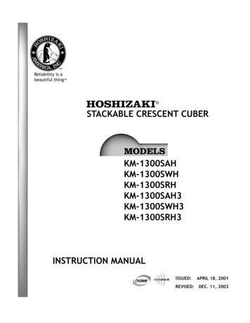
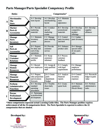
2. Condensing UnitURC-12F11
SPECIFICATIONSMODEL: URC-12FEXTERIORGalvanized SteelDIMENSIONS (W x D x H)35 - 11/16” x 15-11/16” x 21-15/16”(907.2 x 398 x 557.8 mm)REFRIGERANT CHARGEURC-12FR404A 4 lbs. 7 oz. (2000 g)WEIGHTNet 80 lbs. (36 kg)Shipping 87 lbs. (39 kg)CONNECTIONSREFRIGERANTELECTRICALOne Shot Couplings (Aeroquip)Permanent ConnectionCONDENSERAir-cooledHEAD PRESSURE CONTROLCondensing Pressure RegulatorAMBIENT CONDITIONMin. -20 F - Max. 122 F(-29 C to 50 C)Outdoor use12
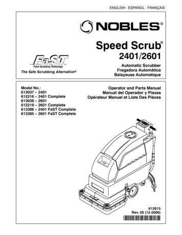
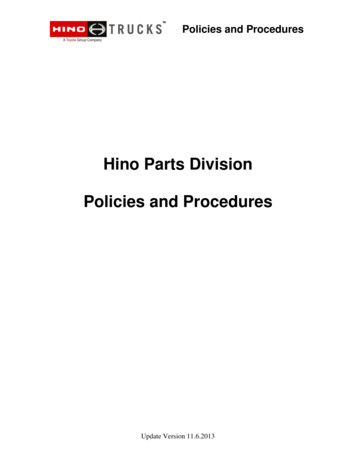
II. General Information1. Construction[a] KM-1300SAH, KM-1300SAH313
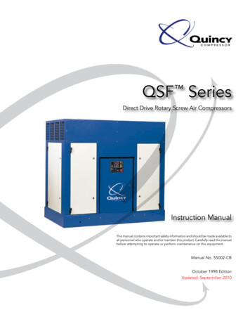
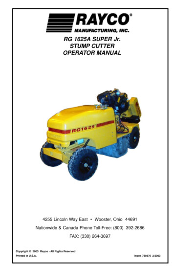
[b] KM-1300SWH, KM-1300SWH314
[c] KM-1300SRH, KM-1300SRH315
2. Controller Board[a] Solid-State Control1) A HOSHIZAKI exclusive solid-state control is employed in KM-1300SAH, KM-1300SWH,KM-1300SRH, KM-1300SAH3, KM-1300SWH3, and KM-1300SRH3 Stackable CrescentCubers.2) A printed circuit board (hereafter called “controller board”) includes a stable and high qualitycontrol system.3) All models are pretested and factory-adjusted.[b] Controller BoardCAUTION1. Fragile, handle very carefully.2. A controller board contains integrated circuits, which are susceptible to failure due tostatic discharge. It is especially important to touch the metal part of the unit whenhandling or replacing the board.3. Do not touch the electronic devices on the board or the back of the board to preventdamage to the board.4. Do not change wiring and connections. Do not misconnect K3, K4 and K5, becausethe same connector is used for the thermistor and float switch. K4 is not connected.5. Always replace the whole board assembly when it goes bad.6. Do not short out power supply to test for voltage.PART NUMBER2A1410-01TYPEHOS-001A (Control Products - 10 Pin)Features of Control Products “E” Controller Board(1) Maximum Water Supply Period - 6 minutesWater solenoid valve opening in the defrost (harvest) cycle is limited by the defrost timer. Thewater valve cannot remain open longer than the maximum period. The water valve can close inless than six minutes if the defrost cycle is completed.(2) Defrost TimerThe defrost cycle starts when the float switch opens and completes the freeze cycle. But thedefrost timer does not start counting until the thermistor senses 48 F at the evaporator outlet.The period from the end of the freeze cycle up to the point of the thermistor's sensing variesdepending on the ambient and water temperatures.16
(3) High Temperature Safety - 127 7 FThe temperature of the suction line in the refrigerant circuit is limited by the high temperaturesafety. During the defrost cycle the evaporator temperature rises. The thermistor senses 48 Fand starts the defrost timer. After the defrost timer counts down to zero, the normal freeze cyclebegins. If the evaporator temperature continues to rise, the thermistor will sense the rise intemperature and at 127 7 F the thermistor operates the high temperature safety. This hightemperature safety shuts down the circuit and the icemaker automatically stops. To reset thesafety, turn the power off and back on again. This high temperature safety protects the unit fromexcessive temperature. The control board will beep every three seconds. The white reset buttonon the control board must be pressed with power on to reset the safety.(4) Low Water SafetyIf the pump motor is operated without water, the mechanical seal can fail. To prevent this type offailure, the controller board checks the position of the float switch at the end of the initial oneminute water fill cycle and at the end of each defrost cycle.If the float switch is in the up position (electrical circuit closed), the controller board changes tothe ice making cycle. If the float switch is in the down position (electrical circuit open), thecontroller board changes to a one minute water fill cycle before starting the ice making cycle.This method allows for a low water safety shut down to protect the water pump from mechanicalseal failure. For water-cooled models, if the water is shut off, the unit is protected by the highpressure switch.(5) High Voltage Cut-outThe maximum allowable supply voltage of this icemaker is limited by the high voltage cut-out. Ifmiswiring (especially on single-phase, 3-wire models) causes excessive voltage on thecontroller board, the high voltage cut-out shuts down the circuit in 3 seconds and the icemakerautomatically stops. When the proper supply voltage is resumed, the icemaker automaticallystarts running again. The control board will signal this problem using 7 beeps every 3 seconds.6) LED Lights and Audible Alarm SafetiesThe red LED indicates proper control voltage and will remain on unless a control voltageproblem occurs. At startup a 5 second delay occurs while the board conducts an internal timercheck. A short beep occurs when the power switch is turned ON or OFF.17
The green LED’s 1-4 represent the corresponding relays and energize and sequence5 seconds from initial startup as follows:Sequence Step1 Minute Fill CycleHarvest CycleCycleReverse Pump OutLED’s on Length:LED4LED1, 4, & 2LED1LED1, 3, & 2Min.Max.2 min.5 min.10 sec.20 min.60 min.20 sec.Avg.60 sec.3-5 min.Freeze30-35 min.Factory set.{LED 1 – Comp; LED 2 - HGV/CFM; LED 3 – PM; LED 4 - WV}The built in safeties shut down the unit and have alarms as follows:1 beep every 3 sec. High Evaporator Temperature 127 F.Check for defrost problem (stuck HGV or relay), hot water entering unit, stuck headmaster, orshorted thermistor.2 beeps every 3 sec. Defrost Back Up Timer. Defrost 20 minutes.Orange LED marked 20 MIN energizes.Check for open thermistor, HGV not opening, TXV leaking by, low charge, or inefficient compressor.3 beeps every 3 sec. Freeze Back Up Timer. Freeze 60 minutes.Yellow LED marked 60 MIN energizes.Check for F/S stuck closed (up), WV leaking by, HGV leaking by, TXV not feeding properly,low charge, or inefficient compressor.To manually reset the above safeties, depress white alarm reset button with the power supplyON.6 beeps every 3 sec. Low Voltage. Voltage is 92 Vac or less.7 beeps every 3 sec. High Voltage. Control voltage 147Vac 5%.The red LED will de-energize if voltage protection operates.The voltage safety automatically resets when voltage is corrected.The Output Test switch “S3” provides a relay sequence test. With power OFF, place S3 ONand switch power to ICE. The correct lighting sequence should be none, 2, 3, 4, 1, & 4, normalsequence every 5 seconds. S3 should remain in the “OFF” position for normal operation.The application switch located between relay X3 & X4 must be set to match the original boardapplication. Place this switch in the ALP position if there is no white wire supplied to the K1connector. If there is a white wire, place the switch in the C position. If this switch is placed inthe wrong position either the compressor contactor will remain energized with the control switchOFF or the unit will not start.18
The dip switches should be adjusted per the adjustment chart published in the Tech Specsbook. 7 & 8 must remain in the OFF position.(Control Products HOS-001A Board)19
[c] Sequence1st Cycle3. Thermistor reads 48 F.Defrost Timer starts counting.1. Unit energized and Control Switch to “ICE”position. Water supply cycle starts.2. After 1 minute.Defrost cycle starts.IMPORTANTWater Valveopening is limitedto 6 minutes.5. After the first 5 minutes in freeze cycle.Ready to complete freeze cycle when FloatSwitch circuit opens.4. Defrost Timer stops counting.Defrost cycle is completed and freeze cyclestarts.IMPORTANTBoard never accepts freeze completion signalwithin the first 5 minutes in freeze cycle.IMPORTANT1. Board never accepts defrost completion signalwithin the first 2 minutes in defrost cycle.2. Defrost cycle time is limited to 20 minutes evenif Defrost Timer does not stop counting.20
2nd Cycle and after with pump drainIMPORTANTFreeze cycle time is limited by the freeze timerfactory setting even if the Float Switch doesnot open.2. Drain timer stops counting.Pump drain is completed1. Float Switch opens and signals to completefreeze cycle.Drain timer starts counting.3. Thermistor reads 48 F.Defrost Timer startscounting.IMPORTANTWater Valveopening is limited to 6minutes.&5. After the first 5 minutes in freeze cycle.Ready to complete freeze cycle when FloatSwitch circuit opens.IMPORTANTBoard never accepts freeze completion signalwithin the first 5 minutes in freeze cycle.4. Defrost Timer stops counting.Defrost cycle is completed and freeze cyclestarts.IMPORTANT1. Board never acc
HOSHIZAKI provides this manual primarily to assist qualified service technicians in the service and maintenance of the icemaker. . KM-1300SRH, KM-1300SAH3, KM-1300SWH3, and KM-1300SRH3 Stackable Crescent. 20 & KM-1300SRH KM-1300SRH3. 30 [c] KM-1300SRH, KM-1300SRH3. 2. parts.