Transcription
Modern Snares for Capturing Mammals:Definitions, Mechanical AttributesandUse ConsiderationsAssociation of Fish and Wildlife AgenciesFurbearer Conservation Technical Work Group2009
ACKNOWLEDGEMENTSThis document was produced by the Association of Fish and Wildlife Agencies (AFWA)Furbearer Conservation Technical Work Group, in consultation with representatives fromtrapping organizations and snare manufacturers. We especially acknowledge Dr. John Erb of theMinnesota Department of Natural Resources, Forest Wildlife Populations and Research Groupfor serving as primary author on this document. We acknowledge Alan Huot for providingnumerous photos. Cover illustration used by permission of Nomadics Tipi Makers.The Association of Fish and Wildlife Agencies was founded in 1902. Itis an organization of public agencies charged with the protection andmanagement of North America’s fish and wildlife resources. The 50state fish and wildlife agencies, as well as provincial and territorialgovernments in Canada are members. Federal fish and wildlife andnatural resource agencies in Canada and the United States are alsomembers. The Association has been a key organization in promotingsound resource management and strengthening state, provincial, federal,and private cooperation in protecting and managing fish and wildlife andtheir habitats in public interest.2Ver. 1.0
TABLE OF CONTENTSINTRODUCTION.5SNARE COMPONENTS .Snare Cable .Snare Locks .Breakaway Devices .Loop Stops .Swivels .669101313SNARING SYSTEM COMPONENTS .Snare-Activation .Capture Area .141415DESCRIBING MODERN SNARES .15SNARE PERFORMANCE .Killing versus Live-Restraining Animals .Selectivity .Snare Efficiency .16161921CONCLUSIONS .233Ver. 1.0
FORWARD“Modern Snares for Capturing Mammals” is primarily intended as a reference document forresource professionals, but may have utility in various educational forums. Our goals are to offerdefinitions of snares and snare components, describe the various types of and uses for snares, anddiscuss various factors that may influence important snare performance attributes. While somediscussion focuses on user-controlled variables, this document is NOT intended as a snaring‘How To’ guide, nor does it recommend specific snares or snare components. The appropriatedesign and use for a snare will vary depending on species, time and location, and multipledesigns may accomplish the same objective. Furthermore, additional scientific data on snareperformance is necessary before wide-ranging comparisons of different snare designs can bemade. As such, we hope this document stimulates continued research and development ofsnaring systems. Depiction of, or reference to, specific snares or snare components does notconstitute a recommendation or endorsement by AFWA. This document may be updatedperiodically and updates will be posted at the AFWA furbearer website(www.fishwildlife.org/furbearer.html).4Ver. 1.0
Modern Snares for Capturing Mammals:Definitions, Mechanical Attributes, and UseConsiderations INTRODUCTIONSnares represent one of the oldest devices used for capturing animals. Their use dates backthousands of years, as evidenced by their depiction in cave drawings. While some snares areconcealed under dirt or snow, snares are most commonly placed along existing animal travelroutes, or along the anticipated path of travel an animal may use when approaching bait or otherattractant. They can be, and historically were, designed or deployed to capture animals by theneck, torso, leg, or foot. While the basic principles behind snare use have changed little throughtime, the physical and mechanical options for snare design have greatly expanded, and snaresremain a popular capture device among licensed fur trappers, animal damage controlprofessionals, and increasingly among wildlife biologists.Historically, snares were constructed of various plant or animal fibers, and lacked reliablemechanisms (i.e., locks) that not only allowed loop formation and smooth loop closure, but alsoprevented the snare loop from easily re-opening once the animal stopped applying pressure. As aresult, snares either had to be tended with great frequency in order to dispatch captured animalsshortly after capture, or set in a manner that would facilitate rapid death (e.g., use of ‘springpoles’). Otherwise, live-restrained animals would frequently be able to break or chew throughthe snare and escape. With the advent of metal snare components (wire, locks, swivels, etc),both the efficiency and versatility of modern snares have improved. Users now have greaterflexibility to use snares as either live-restraining or killing devices, and a variety of options areavailable that can influence various performance attributes (injury reduction, rapidity of death,capture efficiency, selectivity, etc.).In spite of numerous improvements, laws and regulations in some states still prohibit use ofsnares, often dating back 50 - 100 years. Past concerns were frequently based on the belief thatsnares were highly effective but indiscriminate capture devices that allowed little user control ofthe capture outcome (e.g., live-restraint versus death). This led to concerns that snares could5Ver. 1.0
facilitate over-harvest of furbearer populations, and could negatively impact other gamepopulations (e.g., deer). While the goals of harvest selectivity and population conservationcertainly remain important in modern wildlife management, many of the premises underlyingpast concerns are either less relevant today, or new options exist for minimizing those concerns.Recently, there has been renewed interest by natural resource agencies to better understandsnares as a device for capturing mammals. This interest has arisen for several reasons, includingcontinued development of new designs or mechanical options for snares, evolving stateregulations governing snare use, the development of Best Management Practices for trapping,and increased potential for use in wildlife research. While these developments have highlightedthe potential versatility and humaneness of snares, they have also highlighted the need forincreased awareness of modern snares amongst resource professionals, and the need tostandardize terminology used for describing snares and snare components. The lack offamiliarity and language consistency has produced confusion among the various constituents andultimately hindered efforts to increase awareness of modern snares.SNARE COMPONENTSBefore offering descriptions and definitions of snare components, we first offer a basic definitionof a snare. While our definition of a snare emphasizes wire as the primary material used in theconstruction of modern snares, we acknowledge that more ‘primitive’ materials (e.g., plant oranimal fibers) may still be used in some situations or locations, and that alternative modernmaterials could be developed or used in the future.Snare - a type of capture device that uses a loop of wire, stranded wire, or wire rope designedand set to close around the neck, torso, foot or leg of an animal.While we are unaware of any official standard for describing or defining snare components,where possible we have adopted definitions that are generally consistent with industry language.We recognize our definitions do not supplant any current language used in individual statepolicies or laws. Nevertheless, we encourage states to adopt consistent language to minimizeconfusion amongst snare manufacturers, snare users, and natural resource agencies.Snare CableThe material that forms the loop of a snare and extends to the point at which the snare isanchored is frequently referred to as the snare ‘cable’. Modern snare cable is typicallyconstructed with some type of wire (e.g., galvanized or stainless steel). The cable forms theprimary component to which most other components are attached. We offer the followingdefinitions to clarify both the material and design of modern snare cable.Wire - a continual span of metal that has been produced by compression and elongation of largerdiameter metal rods.6Ver. 1.0
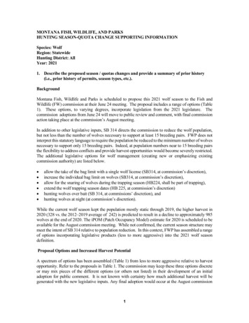
Strand - an assembly of multiple wires that are helically woundaround an axis, fiber, or wire center.While single-wire snare designs have been used in the past, and arestill commonly used for snaring snowshoe hares, most current snaredesigns employ multi-wire construction. The common conventionfor labeling these multi-wire designs is: # of strands times the # ofwires per strand. For example, 7 X 7 means the design iscomposed of 7 strands, with 7 wires per strand, yielding a total of49 wires. Such material is often categorized by the number ofstrands:Single-Strand construction - composed of a single strand; oftenreferred to as ‘stranded wire’. Examples most familiar to trappersinclude 1X19, and 1X7. We emphasize that “single-strand” doesNOT equate with “single-wire”.1Multi-Strand construction - composed of multiple strands; oftenreferred to as ‘wire rope’ or ‘cable’. Examples familiar to trappersinclude 7X7, and 7X19.26153Note: Within the trapping community, both single-strand andmulti-strand material is generically referred to as ‘cable’.Hereafter, we use the term ‘cable’ to denote any multi-wire design.41X7The above strand definitions describe differences in overall cableconstruction. However, it is also important to understanddifferences in construction of an individual strand.Single-Layer Strand – strand with only 1 layer of wireshelically wound around the axis, fiber, or wire center.This strand construction is used, for example, in 1X7 stranded wireand in each individual strand for 7X7 wire rope. In 1X7 and 7X7,the 7-wired strand(s) are constructed with a ‘1-6 single-layer’design, meaning 6 wires helically wound around 1 center wire.Two-Layer Strand – strand with 2 separate layers of wireshelically wound in opposite directions around the axis, fiber, orwire center.12312111261059143546781X19This construction is used, for example, in 1X19 stranded wire andin each of the seven strands of 7X19 wire rope (not shown here).In both, the 19-wired strand(s) are constructed with a ‘1-6-12 twolayer’ design, meaning a center wire with 6 wires wound around itone direction, and 12 more wires wound in the opposite direction.77X7Ver. 1.0
In either single-strand designs with 2-layer construction (e.g., 1X19) or multi-strand designs(e.g., 7X7, 7X19), it is possible for the ‘lay’ of the wires to occur in both clockwise and counterclockwise directions. Lay can include both the direction wires are helically wound within astrand and the direction individual strands are helically wound in multi-strand cable.Lang lay - design where all the strands or wires are helically wound in the same direction. Anexample includes 1X7 (single-strand, single-layer construction).Regular or alternate lay - design where the strands or wires are helically wound in bothdirections. Examples include 7X7, 1X19, and 7X19.Lang lay cable is typically not recommended in applications that involve excessive rotationbecause individual wires may be more apt to separate during twisting, or may separate easier ifan animal bites on the cable. Wire separation predisposes the cable to breakage. Thus, it maynot be as suited to snaring applications where the intent is to live-restrain an animal, or if used insuch situations, might require larger diameter cable or appropriate swiveling. This highlights theimportance of understanding the cable design – design can influence various functionalattributes. To further illustrate how design can influence potential performance, and forcomparative purposes only, the table below shows approximate breaking strength for 24examples.Breaking Strength 0012009205/64”800?8006501/16”500480500480Note: these are approximations for galvanized wire designs based on static load testing. Breaking strength forstainless steel is typically comparable, or slightly less. Numbers will vary depending on manufacturer or grade.DIAMETERWhile there will be some minimum breaking strength necessary for a given species orapplication (live-restraining versus killing), final choice of design may be most driven by otherperformance attributes or user preference. For example, cable design also influences attributessuch as flexibility and surface smoothness. For a given diameter, the more wires, the moreflexible the material, and the more strands, the ‘rougher’ the outer surface. These in turn canaffect snare loop shape (e.g., oval versus round), speed of initial loop closure, resistance to loopclosure as the loop gets smaller, abrasion-resistance, fatigue resistance, etc. Overall, the physicaloptions users may consider in a ‘cable’ include the diameter, design (e.g., 7X7, 1X19), andmaterial (e.g., galvanized, stainless steel).The material used to form the snare loop is only 1 component of a snare. Other components forwhich definitions are warranted include snare locks, loop stops, swivels, and breakaway devices.8Ver. 1.0
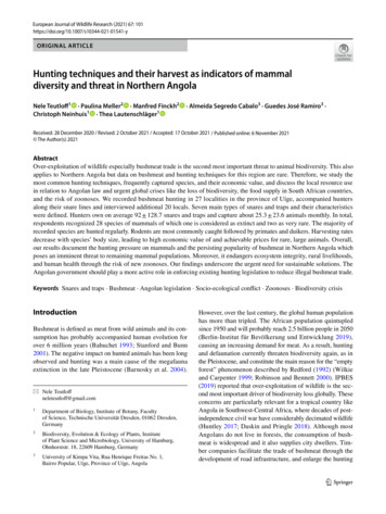
Snare LocksSnare locks are used for 2 purposes: 1) to create and maintain a loop; and 2) to prevent the loop,after closure upon an animal, from re-opening to a diameter that allows the desired animal toescape. The type of snare lock used may also be an important feature in determining thelethality of a snare. We note that a snare does not have to have a mechanically separate lockincorporated into the design to constitute a snare. In some locations or situations (e.g., rabbitsnares, under-ice beaver snares), the snare loop may be formed and held in place by simplythreading the cable through a small loop or knot in the end of the cable. While such ‘lock-less’snares may have reduced holding efficiency, they are successfully used in some situations.There are a multitude of snare locks currently available, andundoubtedly many more to be developed. Numerousexamples are shown in the adjacent figure. For snaresincorporating a locking device, we offer the followingdefinitions to more specifically classify the array of existingsnare locks:Relaxing Lock – a snare lock that allows the snare loop torelease constriction pressure on the captured animal whenthe cable is not taut (e.g., when the animal stops pulling).Positive Lock – a snare lock that neither allows the snare loop to release constriction pressure onthe captured animal, nor is capable of applying additional closing force, when the cable is nottaut.Power-Assisted Lock – a snare lock that uses a built-in or external feature or mechanical devicethat continues to provide a closing force when the cable is not taut (i.e., after the animal stopspulling).Lock Definition Caveats¾ With the exception of locks that are power-assisted, it is not always possible to classify alock based on visual appearance. Locks that appear similar may perform differently, andlocks that appear different may perform similarly.¾ The actual performance of a lock is based not only on the design of the lock itself, but onthe size or design of the cable to which it is attached. For example, depending on lockdesign, a lock may perform as a relaxing lock on a 1/16” cable, but as a positive lock on alarger diameter cable (such as 3/32”). Some locks may be designed or intended for use withspecific cable sizes and/or designs.¾ Some locks (e.g., traditional washer locks) may be placed on the ‘cable’ in differentconfigurations, possibly yielding different performance.¾ Any alteration of a lock from its manufactured condition may affect performance.Examples include changing the angle of any bends in the lock, the size or shape of the holesor slots through which the cable passes, or filing ‘teeth’ into the binding surface of a lock.¾ Under normal field application, numerous external factors may affect the ability of a lock toperform as designed. For example, if a significant bend or kink forms in the cable justoutside the lock position, if the lock becomes bound in the animal’s hair, or if the animalcannot release tension on the cable due to ‘entanglement’, a relaxing lock may not be able to‘relax’ as designed.9Ver. 1.0
Most snare locks currently available would be considered positive locks, though many locks canbe converted to power-assisted locks by the addition of a spring or other powering device. Threeexamples of power-assisted locks are shown below.Breakaway DevicesBreakaway devices are used to improve the selectivity of a snare, and can be designed in manyways. They can be incorporated into the snare lock (as a component or as the structural materialitself), or as an attachment to the snare lock or cable. Breakaway devices are typically ratedbased on the amount of force necessary to cause the loop to ‘break’ or release (e.g., a 285 lb. Shook). The desired rating is based on both the minimum rating necessary to hold the desiredanimal, and the maximum rating allowable for release of other animals. As such, the need forbreakaway devices, and the desired rating if used, will vary in different areas of the country, andmay involve trade-offs between achieving desired selectivity and maintaining acceptableefficiency for the intended species.We illustrate breakaway devices with several examples below, but discuss applications andissues later (see pp. 21-22). Importantly, presence of some breakaways cannot be determinedvisually (e.g., slide-off ferrules or some shear pins).Breakaway Device – any device incorporated into a snare or snare component that allows theloop to break open, and an animal to escape completely free of the snare, when a specifiedamount of force is applied.Shear PinShear PinJ-hookFerrule that slides off10S-hookLock material that shearsVer. 1.0
Issues and Concerns with Measuring or Recommending Breakaway ForceWe note that more research data is necessary to determine the minimum poundage ratingnecessary to hold different animals of interest, and the maximum rating allowable to release anyanimals that are to be avoided. There are 2 additional concerns about breakaway measurements:¾ Currently there is no standardized methodology for measuring breakaway force. Becausesnares, or snare parts, are manufactured, used, and sold by numerous individuals andcompanies, a standardized methodology for measuring breakaway tension wouldminimize the inconsistencies that currently exist.¾ When breakaways are required by law, or advertised by manufacturers, the protocol usedto rate the breakaway is often not specified. Specifying a number without a protocol forhow it’s measured may not be useful, and if required by law, is difficult to enforce. Thesame exact device measured in two distinct ways could yield substantially differentbreakaway ratings.We believe a standardized protocol is desirable, considering 3 important features:¾ To be accessible to the greatest number of potential users, the testing approach should beas mechanically simple and inexpensive as possible.¾ The protocol must not only specify the measuring apparatus, but also any important snarespecifics during testing such as loop size or the material to which the loop is attachedduring testing (e.g., a steel pipe).¾ The measuring apparatus and testing protocol should not contribute to significantvariability in results. When testing multiple devices of identical design, observedvariation in results should be attributable primarily to variability or inconsistency in thebreakaway device itself.Considering the factors above, we recommend the use of a static load test for ratingbreakaway devices. A static load test uses non-moving weight or non-jolting force applied tothe snare.There are numerous ways to design a static load test. Provided the principle of a static nonjolting force is maintained, most testing designs should provide acceptably comparableresults. However, there may still be some trade-offs between the sophistication or cost of atesting system and the resulting precision. Because the acceptable cost and desired precisionwill vary depending on the situation or entity involved in the testing, herein we do notrecommend a specific testing apparatus, with 1 exception: some research has shown that thediameter of the snare loop during testing will influence breakaway ratings. Hence, forstandardization, we recommend the snare loop be cinched around a 2-inch steel pipeduring testing. We note that a “2-inch pipe” has an actual outside diameter of 2.4inches, while the inside diameter varies depending on wall thickness of the pipe.11Ver. 1.0
We do not believe, for a static load test, that the length of the snare will have any appreciableinfluence on breakaway ratings. While snare cable can stretch when tension is applied, thepotential is quite low that any stretching will occur for the typical snare lengths used andloads applied, and any stretching that may occur is not likely to be a noteworthy componentof breakaway variability. We acknowledge, however, that after a breakaway device israted, subsequent field testing to evaluate efficiency and selectivity for a specificapplication (e.g., capture wolves but release moose) should always report the length ofsnare tested, as snare length will have an impact on efficiency and selectivity.Although we only recommend one component of the static load test (i.e., cinch the looparound a 2-inch steel pipe), we do discuss 2 possible testing methods as a way to illustratepossible approaches.1) Use of weights – the snare is suspended from a rigid anchoring point, with the snare loopcinched around a 2” steel pipe. Attached to and hanging below the steel pipe is a ‘loadtray’ upon which weights of the desired increment are sequentially placed until thebreakaway device releases. The breakaway poundage rating is the sum of the load trayweights, the weight of the tray, and the weight of the steel pipe. In such a design, it isimportant to ensure that weights are gently placed, not dropped, on the load tray. Uponrelease, the weight tray will drop, requiring careful safety considerations.2) Use of slow-pull devices and load scales – in this type of design, the testing apparatuscould be positioned vertically or horizontally. On 1 end is a stationary device used togenerate tension on the snare. Examples include a hydraulic cylinder, an electric winch,or a ratcheting pulley. Attached to this force-generating mechanism is a device toquantify the amount of force being exerted. Examples include a heavy-duty spring scaleor more sophisticated digital strain gauge or load cell. The anchor end of the snare isthen attached to the measuring scale, while the snare loop is cinched around a 2” steelpipe (with pipe attached to a fixed point). As tension is slowly increased, the measuringscale should preferably record the maximum force upon breaking, rather than requiring aperson to read it during the test. Because there will be tension on the snare upon release,appropriate safety is warranted.We note that there will be some amount of breakaway variability attributable to quality controlduring breakaway manufacturing. Manufacturers or researchers involved in determining a ratingfor a particular breakaway device should consider an appropriate sample size for quantifyingvariability, and if applicable, those involved with determining compliance with breakawayrecommendations or laws must consider how much variation is acceptable.12Ver. 1.0
Loop StopsA loop stop is a device that is attached to the snare cable to prevent the loop from either openingor closing beyond a specified point. They can be placed either inside or outside the loop, therebydetermining either a minimum or maximum loop circumference. Loop stops are consideredoptional snare components, and while used most commonly to influence selectivity, they canalso influence snare lethality and efficiency (see pp. 17, 20, 21, and 22).Minimum Loop Stop – a device incorporated inside the snare loop that prevents the loop fromclosing beyond a specified circumference.The term “deer stop”, commonly used by many, should be considered a specific application fora minimum loop stop (i.e., a stop that prevents loop closure smaller than the diameter of a deer’sleg).Maximum Loop Stop - a device incorporated outside the snare loop that prevents the loop fromopening beyond a specified circumference.SwivelsSwivels are often incorporated into a snare to prevent the wires or strands in a cable fromkinking or separating, and ultimately breaking, if an animal twists or rolls. While they areprimarily intended to improve capture efficiency of snares (see p. 22), they may play a role inother snare performance measures (see p. 18).In-line swivels may be used instead of, or in conjunction with, end swivels, and may beparticularly useful in situations where there is concern that the anchoring system, or vegetationbetween the anchor and the animal, could cause the end swivel to become effectively inoperable.The closer the in-line swivel is to the animal, the more likely it will retain its intendedeffectiveness.End Swivel - a device incorporated at the point where the snare is attached to a stake, tree, orother anchoring point that allows the snare to freely rotate if the animal twists or rolls.In-line Swivel – a device incorporated between the anchoring point and the opened snare loopthat allows the snare to freely rotate if the animal twists or rolls.Many swivel designs are currently available, and a few examples are shown below.Snare ActivationEnd swivelIn-line swivelIn-line swivel13End and In-line swivelVer. 1.0
SNARING SYSTEM COMPONENTSIn addition to the components that make up the actual snare, some snaring systems utilizeadditional components designed to achieve specific performance goals (e.g., targeting a specificcapture area on the animal, improving killing power, improving efficiency, etc). Many, but notall, of these designs have been developed for specialty purposes in wildlife research or animaldamage control settings. In particular, components have been developed to power-activate loopclosure or directionally-propel snares onto an animal or a specific part of an animal’s body.Snare-ActivationThe vast majority of snares in use today are ‘activated’ simply by the animal moving through thesnare. However, some specialty snaring systems now rely on power-activation, typically toincrease the speed of loop closure or to directionally propel the snare onto an animal’s body. Wedifferentiate snare activation based on whether loop closure utilizes only the movement of theanimal, or whether it also utilizes a powering mechanism.Power-Activated Snare – a snare on which the loop closure (speed or direction) is initiated oraugmented by some type of powering device (e.g., a spring).For power-activated snares, some type of pushing or pulling force applied by the animaltypically serves to trigger the powering mechanism. Four examples are shown below.Belisle foot snareRAM Power SnareFremont foot snareCollarum Passively-Activated Snare – a snare on which the initial loop closure is solely a function of theanimal’s movement.While the 4 examples shown above all incorporate power-activation, the snaring systems differsignificantly in their intended use and performance (e.g., intended capture location, killing versuslive-restraint). We emphasize the important distinction between a power-activated snare and apower-assisted snare lock. Power-activation is used only to control the speed and/or direction inwhich the snare loop is initially propelled or closed on the animal. A power-assisted lock isintended to increase killing power of a snare by applying constriction pressure on the loop whenthe cable is not taut. Snares may have power activation, power-assisted locks, neither, or both.For at least one snaring system – the RAM power snare - the same mechanism used to poweractivate the snare also serves as the power-assisted lock (i.e., it is intended as a ‘killing snare’).In other cases the power-activation components may ‘fall free’ from the snare, relying on a snare14Ver. 1.0
lock to maintain loop closure - examples include the Belisle, Aldrich, or Fremont foot snares, orthe Collarum neck snare.Capture AreaWith respect to capture location, we reiterate that snares can be designed or deployed to captureanimals by the neck, torso, leg, or foot. The most commonly used snares have no specificmechanical features designed to facilitate capture of an animal by only one specific body portion.Depending on user-controlled deployment details, the snare could be used to capture the desiredanimal by the foot, leg, neck, or torso. For example, a snare set above, but close to, the groundmay facilitate leg or foot capture as an animal walks through, while the same snare set suspendedhigher off the ground over a trail may facilitate capture of an animal by the neck or torso. Theappropriate or possible catch location (foot, leg, torso or neck) may vary by species, location,intended outcome (killing versus restraining), injury-potential during live-restraint, or concernsover fur damage (torso captures may result in more fur damage). Users can influence thelikelihood of catching an animal by a specific body portion by considering such factors as: 1)loop size; 2) height of the loop off the ground or compacted snow; 3) loop orientation; and 4)natural or unnatural ‘guides’ to direct animal movement. In addition, some specialized snaringsystems are now available that rely on additional mechanical components or other featuresspecifically designed to facilitate capture of an animal by a particular body area.Specialty foot snares are typically designed with power activation and are often concealed underthe dirt or snow. When an animal pushes or pulls a trigger with its foot, a throwing arm or othermechanism raises or closes the snare over the animal’s foot or leg. Examples of power-activatedfoot snares include the Aldrich, Belisle, M15, and Fremontfoot snares (some
confusion amongst snare manufacturers, snare users, and natural resource agencies. Snare Cable The material that forms the loop of a snare and extends to the point at which the snare is anchored is frequently referred to as the snare 'cable'. Modern snare cable is typically constructed with some type of wire (e.g., galvanized or stainless .