Transcription
MuCellMicrocellular Foaming Technologyfor Injection Molding Industry
MuCell Molding TechnologyThe most significant plastic processinginnovation in the last 20 yearsThe MuCell microcellular foam injection molding process forUnlike chemical foaming agents, the physical MuCell processthermoplastics materials provides unique design flexibility andhas no tempertature limitation and does not leave any chemicalcost savings opportunities not found in conventional injectionresidue in the polymer; making consumer products perfectlymolding. The MuCell process allows for plastic part design withsuitable for recycling within the original polymer classificationmaterial wall thickness optimized for functionality and not for theand allowing re-grind material to reenter the process flow.injection molding process. The combination of densityThe numerous cost and processing advantages have led to rapidreduction and design for functionality often results in materialglobal deployment of the MuCell process primarily in automotive,and weight savings of more than 20%.consumer electronics, medical device, packaging and consumerBy replacing the pack & hold phase with cell growth, lower stressgoods applications.parts are produced which have enhanced dimensional stabilityand substantially reduce warpage. Cell growth also results in theelimination of sink marks.Reduced CostsDesign Freedom Reduced resin consumption Thin to thick wall flow Faster molding cycle time 1:1 wall thickness rib structure Increased yields Material where needed for function versus flow Smaller molding machine Improved dimensional stability Use of lower cost filled polyolefin material Less warpageSustainabilityFaster to Market Reduced petroleum based material consumption Fewer tooling iterations Reduced molding machine energy consumption Predictable molded part geometry Ability to re-grind / re-use molded parts Ability to mold large parts as single piece Reduced carbon footprint versus solid molding
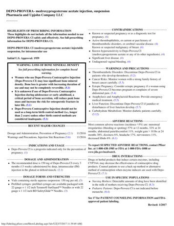
FOURTECHNOLOGYSTEPS124312During plasticization,precisely metered amountsof supercritical fluid (SCF),typically Nitrogen or CO2,are introduced into thepolymer through injectorsmounted on the plasticizingbarrel.Homogeneous mixing anddisbursing of the supercriticalfluid into the polymer throughthe specially designed mixingsection of the plasticizingbarrel, creates a single phasesolution of SCF and moltenpolymer.34Low pressure filling of moldcavities. Pack & hold phaseis replaced by controlled cellgrowth, which ceases oncethe mold cavity is filled. Cellgrowth results in a uniformpack pressure throughout themold cavity.Injection of polymer into moldcavities. Cells start to nucleateonce exposed to lower pressurein the mold cavity. Moleculardispersion of SCF providesfor a homogeneous closed cellstructure with a solid skin layer.MuCell / Polymer Value MatchGood ValueGreat ValueHDPEAcrylicHDPEGlassPVCHIPSPVCPP GlassTPEHIPSTPEPPO BlendsABSPA6/6.6 UnfilledABSPSUTPVGPPSTPVPIEPP UnfilledPOMPP UnfilledPA6/6.6 GlassTPOPBT GlassTPOVirtually all polymers will develop a cellular structure with the MuCell process except for LCP. Filled materials tend to offer thegreatest value as fillers act synergistically with the supercritical fluid to provide the best combination of weight reduction and cycletime reduction. Unfilled amorphous materials also foam very well and can provide good weight reductions but with less cycle timebenefits than filled materials. High temperature materials such as PEEK, PEI and PSU also provide significant cost reduction basedon material price.
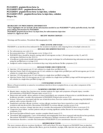
The MuCell Application Advantage:The freedom to design for functionalityand not for plastic process limitationsBy replacing the tradition pack & hold phase of the solid Using the same principle, nominal wall thickness can be reducedmolding process with cell growth, the MuCell processwhile using thicker ribs to meet structural requirements. Theallows for uniform and locally applied pack pressure through cellcell expansion will eliminate sink marks and the cell structuregrowth. This allows part design to be optimized with materialwill prevent the formation of vacuum (shrink) voids. Rib to wallthickness in those areas that require strength and reduced wallthickness ratios of 1:1 can be used with the MuCell process.thickness in areas that are not structural. Gate locations are thenplaced in the thin cross sections for optimized filling patternswhile allowing the cell growth to provide packing in the thickercross sections at the end of fill.Differences in Wall ThicknessesFilling from “thin to thick”Recommendedinjection with MuCell Injection in solid(with MuCell still possible)“A part molded with the MuCell process has a solid skin layer andmicrocellular foamed core which is aclosed cell structure. The cell growthis more effective at packing the partthan the solid pack phase whichallows for increased rib to nominalwall thickness without sink marks. Inmost cases, it is possible to produce asink free part with a rib thicknessequal to the nominal wall thickness”.Wall to rib ratio 1:1 possibleConventional DesignTYPICALSolidMoldingMuCell DesignCYCLETIMEREDUCTIONWITHMUCELL Total 30 Seconds3 sec4 sec17 secTotal 22 SecondsMuCell 1.5 0.5sec sec14 sec6 secInjectionPack & HoldCoolingMotions
MuCell Molding TechnologyThe complete process solution providing for lighter andmore accurate plastic parts at lower production costsAutomotiveClimate Control Bezel Material: Glass filled ABS Elimination of sink marks 1:1 ribs to nominal wall Machine clamping force reduced from 250 tons to 75 tons 23% cycle time reduction 10% weight reductionPackagingThin Wall Margarine Container Material: 70 MFR PP 6% weight / material reduction 15% reduced injection pressure, reducing washout and allowing for thinner in mold label Enhanced freedom of design, thicker sealing lip at the end of fill Machine clamping force reduced by 50%WhiteGoodsCover Plate Material: Filled ASA Premium quality surface features No sink marks / weld lines 30% reduction of material / weight 18% reduction of cycle timeConsumerElectronicsPrinter Bonnet Material: 20% GF PPO/PS Uniform shrinkage and reduced stress result in improved dimensional stability Dimensional compliance achieved with fewer mold iterationsHeightKey DimensionsStd Dev SolidStd Dev MuCell 32.43)0.01550.0035
MC Connector Material: Glass Fiber Reinforced PBT 11% weight / material reduction 18% cycle time reduction Improved pin retention force Smaller standard deviation, consistent pin hole sizeConsumerPower Tool Base Material: PA 6, PA 66 70% warpage improvement 8% weight / material reduction 18% cycle time reductionIndustrialPallet Material: PP/HDPE 10% reduced weight / material Warp reduction for fit / operation of lid Machine clamping force reduced by 50 – 70%ConsumerFootwear Material: TPU Light weight sole components, below 0.3 g/cm3 density 40% improved rebound (ASTM D2632) Use of high performance resin with lower weight
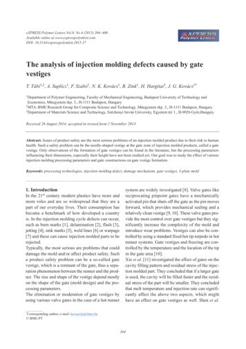
IMPLEMENTINGTHEMUCELL PROCESSThe MuCell capable injection molding machine consists of Nitrogen or CO2 supply, a SCF metering andcontrol system, and a specialized plasticizing unit including positive screw control and a shut off nozzle.Back non-return valveFront non-return valveSCF injectorSCF metering systemShut off nozzleThe technology can be easily integrated into new (OEM Model) or existing (MMU Model) molding machines:MODULAR MUCELL UPGRADE (MMU)Field retrofit of existing injection moldingmachines by qualified Trexel technicians. Theupgrade consists of a new, MuCell capableplasticizing unit, positive screw position control,installation and training.OEM SYSTEMFor new injection molding machine applications, thefollowing licensed Trexel OEM partners can provide aturnkey MuCell injection molding system.
About TrexelThe exclusive provider of the MuCell MicrocellularFoam Injection Molding Technologyhe MuCell Microcellular foaming technology was originallyTFrom the global headquarters in Boston, Massachusetts, Trexelconceptualized and invented at the Massachusetts Instituteoperates a state of the art plastics processing developmentof Technology (MIT) and in 1995 Trexel was granted anlaboratory, supporting plastics processors with the definitionexclusive worldwide license for the further development andand implementation of leading and differentiating plasticcommercialization of the technology. Today, Trexel is the exclusivemolding technologies. provider of the MuCell microcellular foam technology forIn support of a global client base, Trexel operates subsidiariesinjection molding and maintains an extensive global patentin Europe, Japan and Southeast Asia with competent plasticsportfolio. Trexel provides world-class engineering support,processing engineering capabilities. Trexel’s worldwidetraining and other design and processing services, as well as thesubsidiaries are augmented by a network of competentequipment and components integral to the MuCell process.independent representatives and distributors.HEADQUARTERSSUBSIDIARIESTECHNICAL CENTERSTrexel, Inc.100 Research DriveWilmington, MA 01887 USATel.: 781-932-0202www.Trexel.comE U R O P E C H I N A J A PA N K O R E A N O R T HA M E R I C A A U S T R A L I A
Low pressure filling of mold cavities. Pack & hold phase is replaced by controlled cell growth, which ceases once the mold cavity is filled. Cell growth results in a uniform pack pressure throughout the mold cavity. Virtually all polymers will develop a cellular structure with the MuCell process except for LCP. Filled materials tend to .