Transcription
Undercounter Ice Machine Installation Guide
U N DER CO UNT E R ICE MACHINEContentsImportant Note3Undercounter Ice Machine4Opening ion10Custom PanelCAUTION indicates a situation where minor injury or productdamage may occur if instructions are not followed.11CompletionFeatures and specifications are subject to change at anytime without notice. Visit subzero.com/specs for the mostup-to-date information.To ensure this product is installed and operated as safelyand efficiently as possible, take note of the following typesof highlighted information throughout this guide:IMPORTANT NOTE highlights information that is especiallyWARNING states a hazard that may cause serious injury ordeath if precautions are not followed.IMPORTANT NOTE: Throughout this guide, dimensions inparentheses are millimeters unless otherwise specified.IMPORTANT NOTE: Save these instructions for the localelectrical inspector.2 Sub-Zero Customer Care 800.222.7820
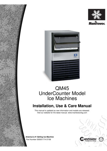
U N DER CO UNT E R ICE MACHINEProduct InformationTools MaterialsImportant product information including the model andserial number are listed on the product rating plate. Therating plate is located in the upper left corner of the icestorage bin, on the back of the unit. Refer to the illustrationbelow. Screwdrivers—standard, Phillips and Torx.If service is necessary, contact Sub-Zero factory certifiedservice with the model and serial number. For the nameof the nearest Sub-Zero factory certified service or forquestions regarding the installation, visit the contact & support section of our website, subzero.com or call Sub‑Zerocustomer care at 800-222-7820. Tubing cutter. Power drill. Standard socket and wrench set. 2' level. 3' (.9 m) of 1/4" OD copper, braided stainless steel orPEX tubing. Saddle valve. Material to protect home, flooring and cabinetry duringinstallation.RATINGPLATERating plate location.subzero.com 3
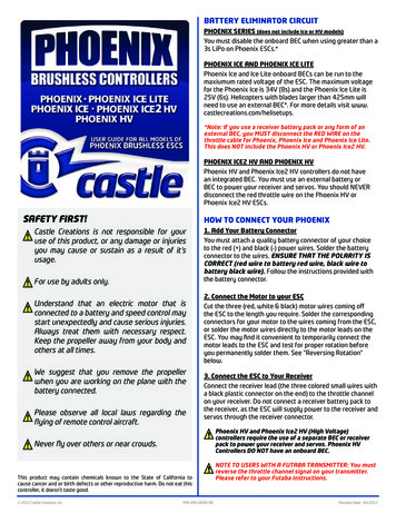
S I T E PR EPAR ATIONOpening DimensionsI C E MACHINE24" (610)OPENINGDEPTHTOP VIEW34 1/2"15 1/4"(876)OPENINGHEIGHT(387)OPENINGWIDTHSIDE VIEWFRONT VIEWIMPORTANT NOTE: It is recommended that the electricaland water supply be placed in an adjacent cabinet. If theyare placed within the opening, additional cabinet depth maybe required.4 Sub-Zero Customer Care 800.222.7820
S I T E PR EPAR ATIONElectricalInstallation must comply with all applicable electrical codes.Although it can be located anywhere on the back wall, itis recommended that the electrical supply be placed in anadjacent cabinet or in the lower right of the opening. Referto the illustration below. A separate circuit, servicing onlythis appliance is required.Model UC-15I(P)O is designed and safe for use in outdoorapplications. When installed outdoors, a ground fault circuitinterrupter (GFCI) is required to reduce the risk of electricalshock. A GFCI is not recommended for use with the indoormodel and may cause interruption of operation.CAUTIONThe outlet must be checked by a qualified electrician tobe sure that it is wired with the correct polarity. Verifythat the outlet is properly grounded.WARNINGDo not use an extension cord, two-prong adapter orremove the power cord ground prong.ELECTRICAL REQUIREMENTSElectrical Supply115 VAC, 60 HzService15 ampReceptacle3-prong grounding-typeEEEElectrical supply location.subzero.com 5
S I T E PR EPAR ATIONPlumbingPreparationInstallation must comply with all applicable plumbing codes.The water supply line should be located as shown in theillustration below. The water supply line should be connected to the house supply with an easily accessible shutoff valve. Do not use self‑piercing valves.A reverse osmosis system can be used provided there isconstant water pressure of 20–80 psi (1.4–5.5 bar) supplied tothe unit at all times. A copper line is not recommended forthis application.PLUMBING REQUIREMENTS1/4"Water Supply LineWater PressureOD copper, braided stainless steel or PEX tubing20–80 psi (1.4–5.5 bar)Excess Water Line for Connection36" (914)I C E MACHINE D RAINThe ice machine can be ordered with or without a drainpump. Models without a pump will drain water by gravity.A drain must be installed.The drain and inlet water tubes must be plumbed beforeconnecting to the ice machine. For the gravity drain, horizontal drain lines must have a 1/4" (6) per 12" (305) fall. Anair gap will likely be required between the unit and drain.A stand pipe with a trap below is acceptable for the drain.8"1/2"(13)(203)24" (610)ROUGHOPENINGDEPTHLOCATION OFWATER LINETOP VIEWWater supply location.15 1/4" min (387)ROUGHOPENING WIDTH341/2" (876)6 POSITION OUTLETROUGHOPENINGHEIGHT33 5/8" (854)Sub-Zero Customer Care fore moving the unit into position, secure the doorclosed and protect any finished flooring.Uncrate the unit and inspect for damage. Remove the woodbase and discard shipping bolts and brackets. Remove andrecycle packing materials. Do not discard the kickplate andhardware.Use an appliance dolly to move the unit near the opening.If the unit has been on its back or side, it must stand uprightfor a minimum of 24 hours before connecting power.
I N S TALLAT IO NInstallation5 OpenI N S TALL ICE MACHINE1 Adjustthe leveling legs close to the desired height. Referto the illustration below.2 Reversethe door swing if needed. Refer to steps outlined on page 9.3 Gravitydrain model: Install the drain hose provided,onto the drain fitting on the back of unit and route tothe open site drain. Refer to the illustration below andplumbing requirements on the previous page. Drain pump model: Route drain tubing through the drainfitting on the back of the unit and install the drain hoseprovided, on the drain pump. Route the other end ofthe drain tubing to the drain site. Refer to the illustrationbelow and plumbing requirements on the previous page.a compression fitting to connect the water inlet onback of ice machine to the prepared 1/4" (6) OD coldwater line. Refer to the illustration below.the shut-off valve on the water line. Check allplumbing connections for leaks. Failure to do so couldresult in flooding.6 Plugthe power cord into the grounded receptacle.7 Levelthe ice machine to assure the door closes andseals properly. Place a level on top of the unit and turneach leveling leg to raise or lower as needed.8 Movethe ice machine into its final position.9 Anchorthe ice machine by installing two flat headscrews provided through each hinge. Refer to the illustration below.4 UseANCHORINGSCREWSDRAIN FITTINGAnchoring.LEVELINGLEGWATER INLETLeveling.Drain connection.subzero.com 7
I N S TALLAT IO NInstallationV E R IF Y ICE PR ODUCTION1 Press‘POWER’ to turn the ice machine on.2 Addone gallon (3.8 L) of cold water to the ice bin. Verifythe water completely drains from the ice bin and thereare no leaks. If the water has not drained within 60 seconds, there may be a kink in the drain tube or incorrectdrain installation.3 Press‘CLEAN’. Wait three minutes until the CLEAN lightflashes, then add 1 tablespoon (15 ml) of undiluted icemachine sanitizer directly into the spray area. Refer tothe illustration below. Use only the sanitizer made for theSub-Zero ice machine available at subzerowolfstore.com.For questions, contact Sub-Zero customer care at800-222-7820.WATERSHUTTERSWater shutters location.8 Sub-Zero Customer Care 800.222.78204 A10-minute sanitizing cycle begins, followed by eightrinse cycles. When the process is complete, the CLEANlight will no longer be illuminated. The entire cycle takesapproximately 30 minutes.5 Atinitial start-up, the ice machine will need approximately 30 minutes to freeze ice cubes and up to fiveminutes to harvest. Verify completion of the first cycle iceproduction to confirm proper installation.
I N S TALLAT IO NInstallation5 RemoveR EVER S E DO O R SWINGThe door hinges are designed to be placed on either theright or left side of the ice machine. The unit is shipped withthe door hinged on the right. Moving the hinges to the left inpre-drilled holes, allows for a left-hand door swing.To reverse door swing:the top cover of the ice machine by removingtwo screws at the top rear of the unit.6 Removefour screws from the front top rail, then pivotthe top rail end for end to expose the two left-hand tophinge mounting holes and reinstall. Refer to the illustration below.7 Remove1 Detachthe hinges from the ice machine by removing twoscrews per hinge, then remove the door. Remove theshim located between the cabinet and bottom hinge, thisshim will transfer to the left side bottom hinge.2 Detachthe hinges from the door by removing twoscrews per hinge.3 Detachthe right-hand upper trim (shaded area) from thedoor by removing two screws. Refer to the illustrationbelow. Replace it with the left-hand upper trim.two screws from the lower edge of the bottomtrim plate and slide it to the right to cover the right hingemounting holes. Refer to the illustration below. The lefthinge mounting holes will now be exposed.8 Reinstallthe shim removed in step 1, between thecabinet and the left side bottom hinge. Reinstall the doorby mounting the hinges using the left hinge mountingholes. Verify operation of door.4 Transferthe hinges to the left side of the door andreinstall. The upper hinge will now be in the lower hingeposition and the lower hinge in the upper hinge position.HINGESCREWSUPPERTRIM (RH)TOP RAILSCREWSHINGETRIM PLATESCREWSFront top rail.Bottom trim plate.HINGERemove door.Detach hinges and trim.subzero.com 9
I N S TALLAT IO NCustom PanelO VER LAY PANELPA N EL I N S TA LLATI O NFor overlay applications, a custom door panel must beinstalled. Panel size is critical for a proper fit. To verify panelrequirements and dimensions, refer to the Sub-Zero designguide at subzero.com/specs.Remove the handle side bracket attached to the front of thedoor. Place the custom overlay door panel face down on aprotected work surface. On the back of the panel, positionthe plastic template provided, flush with the top and sideedges. Verify proper location for right-hand (RH) or left-hand(LH) door swing. Refer to the illustration below.Finish all sides of the custom panel. They will be visiblewhen the door is open.A D-style handle is recommended. The door handle must belocated near the edge of the panel opposite the hinge, centered top to bottom. Stainless steel tubular and pro handlesare avail able through an authorized Sub-Zero dealer. Forlocal dealer information, visit the find a showroom sectionof our website, subzero.com.Mark the holes, remove the template and drill pilot holes forthe brackets. Position and secure the mounting bracket withscrews provided.To install the custom door panel, partially insert a screw inthe center of each mounting position on the hinge side ofthe door. Engage the tabbed bracket to the handle sideof the door, then slide the hinge side mounting bracket ontopositioning screws. Slotted holes on the mounting bracketshould slide under screw heads to support the panel. Referto the illustration below. Panel can be adjusted 1/4" (6) upand down and side to side.Once the custom panel is in place and properly adjusted,attach remaining screws to the hinge side mounting bracketand install hinge covers.DOORPANELBRACKETSCREWCAPTemplate position.10 Sub-Zero Customer Care 800.222.7820Panel installation.
I N S TALLAT IO NCompletionK I C KPLAT E INS TAL L ATIONH I N GE C O V ER SInstall the kickplate using two screws provided. Refer tothe illustration below. The kickplate must be removablefor service. The floor cannot interfere with removal. Do notcover the louvered section of the kickplate.Install hinge covers once installation of the ice machine iscomplete and door stop pins have been installed (if applicable). The knock-out in the hinge cover must be removedif the 90 door stop is used.9 0 DO O R S T O PDoor stop pins provided with the ice machine will limit thedoor swing to 90 .To install, open the door to approximately 80 . Insert onestop pin into the top door hinge (pin enters from the bottom)and the other stop pin into the bottom door hinge (pinenters from the top). Refer to the illustration below. Checkfor proper operation.Verify hinges are free of dirt or grease before applyingcovers. To install, remove paper backing and apply hingecovers to each hinge. Attach the magnetic center covers.Refer to the illustration below.WARNINGFollow all city and state laws when storing, recycling ordiscarding unused refrigerators and freezers.DOOR STOP PINKNOCK-OUT90 door stop.Hinge covers.Sub-Zero, Sub-Zero & Design, Dual Refrigeration, The Living Kitchen, Great American Kitchens The Fine Art of Kitchen Design, and Ingredients are registered trademarks and servicemarks of Sub-Zero, Inc. Wolf, Wolf & Design, Wolf Gourmet, W & Design and the color red as applied to knobs are registered trademarks and service marks of Wolf Appliance, Inc.All other trademarks or registered trademarks are property of their respective owners in the United States and other countries.subzero.com 11
SUB- Z E RO, I NC.P. O. BOX 44848MA D I SO N , WI 5 3 7 4 47024818 REV-C8 / 2016SU B ZER O . C O M800.222.7820
INSTALLATION Installation VERIFY ICE PRODUCTION 1 Press 'POWER' to turn the ice machine on. 2 Add one gallon (3.8 L) of cold water to the ice bin. Verify the water completely drains from the ice bin and there are no leaks. If the water has not drained within 60 sec-onds, there may be a kink in the drain tube or incorrect drain installation.