Transcription
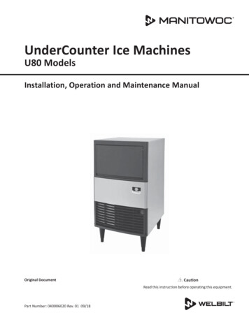
0Front.fm Page 1Thursday, July 17, 2008 3:41 PMQM45UnderCounter ModelIce MachinesInstallation, Use & Care ManualThis manual is updated as new information and models are released.Visit our website for the latest manual. www.manitowocfsg.comAmerica’s #1 Selling Ice MachinePart Number 000001774 07/08
0Front.fm Page 2Thursday, July 17, 2008 3:41 PMSafety NoticesRead These Before Proceeding:As you work on Manitowoc equipment, be sure to payclose attention to the safety notices in this manual.Disregarding the notices may lead to serious injury and/or damage to the equipment.Throughout this manual, you will see the following typesof safety notices:! WarningText in a Warning box alerts you to a potentialpersonal injury situation. Be sure to read theWarning statement before proceeding, and workcarefully.! CautionText in a Caution box alerts you to a situation inwhich you could damage the equipment. Be sure toread the Caution statement before proceeding, andwork carefully.! CautionProper installation, care and maintenance areessential for maximum performance and troublefree operation of your Manitowoc equipment. Readand understand this manual. It contains valuablecare and maintenance information. If you encounterproblems not covered by this manual, do notproceed, contact Manitowoc Foodservice Group.We will be happy to provide assistance.ImportantRoutine adjustments and maintenance proceduresoutlined in this manual are not covered by thewarranty.! WarningPERSONAL INJURY POTENTIALProcedural NoticesAs you work on Manitowoc equipment, be sure to readthe procedural notices in this manual. These noticessupply helpful information which may assist you as youwork.Do not operate equipment that has been misused,abused, neglected, damaged, or altered/modifiedfrom that of original manufactured specifications.NOTE: SAVE THESE INSTRUCTIONS.Throughout this manual, you will see the following typesof procedural notices:ImportantText in an Important box provides you withinformation that may help you perform a proceduremore efficiently. Disregarding this information willnot cause damage or injury, but it may slow youdown as you work.NOTE: Text set off as a Note provides you with simple,but useful, extra information about the procedure youare performing.We reserve the right to make product improvements at any time.Specifications and design are subject to change without notice.
Table of ContentsSection 1General InformationModel Numbers. . . . . . . . . . . . . . . . . . . . . . . . . . . . . . . . . . . . . . . . . . . . . . . . . . .1-1Accessories. . . . . . . . . . . . . . . . . . . . . . . . . . . . . . . . . . . . . . . . . . . . . . . . . . . . . .1-1Tri-liminator Water Filter System . . . . . . . . . . . . . . . . . . . . . . . . . . . . . . . .1-1Manitowoc Cleaner and Sanitizer . . . . . . . . . . . . . . . . . . . . . . . . . . . . . . . .1-1Model/Serial Number Location . . . . . . . . . . . . . . . . . . . . . . . . . . . . . . . . . . . . . .1-2Owner Warranty Registration Card . . . . . . . . . . . . . . . . . . . . . . . . . . . . . . . . . . .1-3General . . . . . . . . . . . . . . . . . . . . . . . . . . . . . . . . . . . . . . . . . . . . . . . . . . . .1-3Commercial Warranty Coverage . . . . . . . . . . . . . . . . . . . . . . . . . . . . . . . . .1-3Residential Warranty Coverage . . . . . . . . . . . . . . . . . . . . . . . . . . . . . . . . .1-4General . . . . . . . . . . . . . . . . . . . . . . . . . . . . . . . . . . . . . . . . . . . . . . . . . . . . . . . . .2-1Ice Machine Dimensions . . . . . . . . . . . . . . . . . . . . . . . . . . . . . . . . . . . . . . . . . . .2-1Location of Ice Machine . . . . . . . . . . . . . . . . . . . . . . . . . . . . . . . . . . . . . . . . . . . .2-2Ice Machine Heat of Rejection . . . . . . . . . . . . . . . . . . . . . . . . . . . . . . . . . . . . . . .2-2Leveling the Ice Machine . . . . . . . . . . . . . . . . . . . . . . . . . . . . . . . . . . . . . . . . . . .2-2Electrical Service . . . . . . . . . . . . . . . . . . . . . . . . . . . . . . . . . . . . . . . . . . . . . . . . .2-3Voltage . . . . . . . . . . . . . . . . . . . . . . . . . . . . . . . . . . . . . . . . . . . . . . . . . . . .2-3Fuse/circuit breaker . . . . . . . . . . . . . . . . . . . . . . . . . . . . . . . . . . . . . . . . . .2-3electrical Rating . . . . . . . . . . . . . . . . . . . . . . . . . . . . . . . . . . . . . . . . . . . . .2-3Water Service/Drains . . . . . . . . . . . . . . . . . . . . . . . . . . . . . . . . . . . . . . . . . . . . . .2-4Water Supply . . . . . . . . . . . . . . . . . . . . . . . . . . . . . . . . . . . . . . . . . . . . . . .2-4Drain Connections . . . . . . . . . . . . . . . . . . . . . . . . . . . . . . . . . . . . . . . . . . .2-4Water Supply and Drain Line Sizing/Connections . . . . . . . . . . . . . . . . . . . .2-4Installation Checklist . . . . . . . . . . . . . . . . . . . . . . . . . . . . . . . . . . . . . . . . . . . . . .2-6Before Starting the Ice Machine . . . . . . . . . . . . . . . . . . . . . . . . . . . . . . . . . . . . .2-6Component Identification . . . . . . . . . . . . . . . . . . . . . . . . . . . . . . . . . . . . . . . . . .3-1Ice Making Sequence of Operation . . . . . . . . . . . . . . . . . . . . . . . . . . . . . . . . . . .3-2Initial Start-up Or Start-up After Automatic Shut-off . . . . . . . . . . . . . . . . . .3-2Freeze Sequence . . . . . . . . . . . . . . . . . . . . . . . . . . . . . . . . . . . . . . . . . . . .3-2Harvest Sequence . . . . . . . . . . . . . . . . . . . . . . . . . . . . . . . . . . . . . . . . . . .3-2Automatic Shut-off . . . . . . . . . . . . . . . . . . . . . . . . . . . . . . . . . . . . . . . . . . .3-2Section 2Installation InstructionsSection 3OperationPart Number 000001774 07/08i
Table of Contents (continued)Energized Parts Chart . . . . . . . . . . . . . . . . . . . . . . . . . . . . . . . . . . . . . . . . . . . . . .3-3Operational Checks. . . . . . . . . . . . . . . . . . . . . . . . . . . . . . . . . . . . . . . . . . . . . . . .3-4General . . . . . . . . . . . . . . . . . . . . . . . . . . . . . . . . . . . . . . . . . . . . . . . . . . . .3-4Siphon System . . . . . . . . . . . . . . . . . . . . . . . . . . . . . . . . . . . . . . . . . . . . . .3-4Siphon System Check . . . . . . . . . . . . . . . . . . . . . . . . . . . . . . . . . . . . . . . . .3-4water Float Valve Check . . . . . . . . . . . . . . . . . . . . . . . . . . . . . . . . . . . . . . .3-4Water Level Check . . . . . . . . . . . . . . . . . . . . . . . . . . . . . . . . . . . . . . . . . . .3-5Ice Bridge Thickness Check . . . . . . . . . . . . . . . . . . . . . . . . . . . . . . . . . . . .3-5Interior Cleaning and Sanitizing . . . . . . . . . . . . . . . . . . . . . . . . . . . . . . . . . . . . .4-1General . . . . . . . . . . . . . . . . . . . . . . . . . . . . . . . . . . . . . . . . . . . . . . . . . . . .4-1Cleaning And Sanitizing Procedure . . . . . . . . . . . . . . . . . . . . . . . . . . . . . . .4-1Ice Machine Inspection . . . . . . . . . . . . . . . . . . . . . . . . . . . . . . . . . . . . . . . . . . . .4-8Exterior Cleaning . . . . . . . . . . . . . . . . . . . . . . . . . . . . . . . . . . . . . . . . . . . . . . . . .4-8Cleaning the Condenser . . . . . . . . . . . . . . . . . . . . . . . . . . . . . . . . . . . . . . . . . . .4-8Removal From Service Winterization . . . . . . . . . . . . . . . . . . . . . . . . . . . . . . . . .4-8Section 4MaintenanceSection 5Before Calling for ServiceiiChecklist . . . . . . . . . . . . . . . . . . . . . . . . . . . . . . . . . . . . . . . . . . . . . . . . . . . . . . . .5-1Safety Limit Feature . . . . . . . . . . . . . . . . . . . . . . . . . . . . . . . . . . . . . . . . . . . . . . .5-2Safety Limits . . . . . . . . . . . . . . . . . . . . . . . . . . . . . . . . . . . . . . . . . . . . . . . .5-3Part Number 000001774 07/08
Section 1General InformationModel NumbersAccessoriesThis manual covers the following models:Contact your Manitowoc distributor for these LIMINATOR WATER FILTER SYSTEMEngineered specifically for Manitowoc ice machines, TriLiminator water filters are an efficient, dependable, andaffordable method of inhibiting scale formation, filteringsediment, and removing chlorine taste and odor.MANITOWOC CLEANER AND SANITIZERManitowoc Ice Machine Cleaner and Sanitizer areavailable in convenient 16 oz. (473 ml) and 1 gal (3.78 l)bottles. These are the only cleaner and sanitizerapproved for use with Manitowoc products.Cleaner Part Number16oz94-0456-31 Gallon 94-0580-3Part Number 000001774 07/08Sanitizer Part number16oz94-0565-31 Gallon94-0581-31-1
General InformationSection 1Model/Serial Number LocationRecord the model and serial number of your ice machinein the space provided below. These numbers arerequired when requesting information from your localManitowoc distributor, service representative, orManitowoc Ice, Inc.The model and serial number are listed on the OWNERWARRANTY REGISTRATION CARD. They are alsolisted on the MODEL/SERIAL NUMBER DECAL affixedto the ice machine.MODEL/SERIALPLATE LOCATIONMODEL/SERIALPLATE LOCATIONModel/Serial Number LocationIce MachineModel NumberSerial Number1-2Part Number 000001774 07/08
Section 1General InformationOwner Warranty Registration CardExclusionsGeneralThe following items are not included in the ice machine’swarranty coverage:The packet containing this manual also includeswarranty information. Warranty coverage begins the dayyour new ice machine is installed.ImportantComplete and mail the OWNER WARRANTYREGISTRATION CARD as soon as possible tovalidate the installation date.If you do not return your OWNER WARRANTYREGISTRATION CARD, Manitowoc will use the date ofsale to the Manitowoc Distributor as the first day ofwarranty coverage for your new ice machine.COMMERCIAL WARRANTY COVERAGEGeneralThe following Warranty outline is provided for yourconvenience. For a detailed explanation, read thewarranty bond shipped with each product.Contact your local Manitowoc representative orManitowoc Ice, Inc. if you need further warrantyinformation.PartsManitowoc warrants the ice machine against defects inmaterials and workmanship, under normal use andservice for three (3) years from the date of originalinstallation.LaborLabor required to repair or replace defectivecomponents is covered for three (3) years from the dateof original installation.1. Normal maintenance, adjustments and cleaning asoutlined in this manual.2. Repairs due to unauthorized modifications to the icemachine or use of non-standard parts without priorwritten approval from Manitowoc Ice, Inc.3. Damage caused by improper installation of the icemachine, electrical supply, water supply or drainage,or damage caused by floods, storms, or other acts ofGod.4. Premium labor rates due to holidays, overtime, etc.;travel time; flat rate service call charges; mileageand miscellaneous tools and material charges notlisted on the payment schedule. Additional laborcharges resulting from the inaccessibility ofequipment are also excluded.5. Parts or assemblies subjected to misuse, abuse,neglect or accidents.6. Damage or problems caused by installation,cleaning and/or maintenance proceduresinconsistent with the technical instructions providedin this manual.Authorized Warranty ServiceTo comply with the provisions of the warranty, arefrigeration service company, qualified and authorizedby your Manitowoc distributor, or a Contracted ServiceRepresentative must perform the warranty repair.NOTE: If the dealer you purchased the ice machine fromis not authorized to perform warranty service, contactyour Manitowoc distributor or Manitowoc Ice, Inc. for thename of the nearest authorized service representative.Service CallsNormal maintenance, adjustments and cleaning asoutlined in this manual are not covered by the warranty.If you have followed the procedures listed in this manual,and the ice machine still does not perform properly, callyour authorized service company.Part Number 000001774 07/081-3
General InformationSection 1RESIDENTIAL WARRANTY COVERAGEWHAT IS NOT COVERED?WHAT DOES THIS LIMITED WARRANTY COVER?This limited warranty does not cover, and you are solelyresponsible for the costs of: (1) periodic or routinemaintenance, (2) repair or replacement of the Product orparts due to normal wear and tear, (3) defects ordamage to the Product or parts resulting from misuse,abuse, neglect, or accidents, (4) defects or damage tothe Product or parts resulting from improper orunauthorized alterations, modifications, or changes; and(5) defects or damage to any Product that has not beeninstalled and/or maintained in accordance with theinstruction manual or technical instructions provided byManitowoc. To the extent that warranty exclusions arenot permitted under some state laws, these exclusionsmay not apply to you.Subject to the exclusions and limitations below,Manitowoc Ice, Inc. (“Manitowoc”) warrants to theoriginal consumer that any new ice machinemanufactured by Manitowoc (the “Product”) shall be freeof defects in material or workmanship for the warrantyperiod outlined below under normal use andmaintenance, and upon proper installation and start-upin accordance with the instruction manual supplied withthe Product.HOW LONG DOES THIS LIMITED WARRANTYLAST?Ice Machine - Twelve (12) months from the sale dateWHO IS COVERED BY THIS LIMITED WARRANTY?This limited warranty only applies to the originalconsumer of the Product and is not transferable.WHAT ARE MANITOWOC ICE’S OBLIGATIONSUNDER THIS LIMITED WARRANTY?If a defect arises and Manitowoc receives a validwarranty claim prior to the expiration of the warrantyperiod, Manitowoc shall, at its option: (1) repair theProduct at Manitowoc’s cost, including standard straighttime labor charges, (2) replace the Product with one thatis new or at least as functionally equivalent as theoriginal, or (3) refund the purchase price for the Product.Replacement parts are warranted for 90 days or thebalance of the original warranty period, whichever islonger. The foregoing constitutes Manitowoc’s soleobligation and the consumer’s exclusive remedy for anybreach of this limited warranty. Manitowoc’s liabilityunder this limited warranty is limited to the purchaseprice of Product. Additional expenses including, withoutlimitation, service travel time, overtime or premium laborcharges, accessing or removing the Product, or shippingare the responsibility of the consumer.HOW TO OBTAIN WARRANTY SERVICETo obtain warranty service or information regarding yourProduct, please contact us at:MANITOWOC ICE, INC.2110 So. 26th St.,P.O. Box 1720,Manitowoc, WI 54221-1720Telephone: 920-682-0161Fax: 920-683-7585www.manitowocice.com1-4EXCEPT AS STATED IN THE FOLLOWINGSENTENCE, THIS LIMITED WARRANTY IS THE SOLEAND EXCLUSIVE WARRANTY OF MANITOWOCWITH REGARD TO THE PRODUCT. ALL IMPLIEDWARRANTIES ARE STRICTLY LIMITED TO THEDURATION OF THE LIMITED WARRANTYAPPLICABLE TO THE PRODUCTS AS STATEDABOVE, INCLUDING BUT NOT LIMITED TO, ANYWARRANTY OF MERCHANTABILITY OR OF FITNESSFOR A PARTICULAR PURPOSE. Some states do notallow limitations on how long an implied warranty lasts,so the above limitation may not apply to you.IN NO EVENT SHALL MANITOWOC OR ANY OF ITSAFFILIATES BE LIABLE TO THE CONSUMER OR ANYOTHER PERSON FOR ANY INCIDENTAL,CONSEQUENTIAL OR SPECIAL DAMAGES OF ANYKIND (INCLUDING, WITHOUT LIMITATION, LOSS OFPROFITS, REVENUE OR BUSINESS) ARISING FROMOR IN ANY MANNER CONNECTED WITH THEPRODUCT, ANY BREACH OF THIS LIMITEDWARRANTY, OR ANY OTHER CAUSE WHATSOEVER,WHETHER BASED ON CONTRACT, TORT OR ANYOTHER THEORY OF LIABILITY. Some states do notallow the exclusion or limitation of incidental orconsequential damages, so the above limitation orexclusion may not apply to you.HOW STATE LAW APPLIESThis limited warranty gives you specific legal rights, andyou may also have rights that vary from state to state orfrom one jurisdiction to another.REGISTRATION CARDTo secure prompt and continuing warranty service, thiswarranty registration card must be completed and sentto Manitowoc within thirty (30) days from the sale date.Complete the following registration card and send it toManitowoc at the address shown.Part Number 000001774 07/08
Section 2Installation InstructionsGeneralThese instructions are provided to assist the 1.90cm 0.63cmPart Number 000001774 07/082-1
Installation InstructionsSection 2Location of Ice MachineThe location selected for the ice machine must meet thefollowing criteria. If any of these criteria are not met,select another location. The location must be indoors. The location must be free of airborne and othercontaminants. The air temperature must be at least 1.6 C (35 F),but must not exceed 43.4 C (110 F). The location must not be near heat-generatingequipment or in direct sunlight. The location must be capable of supporting theweight of the ice machine and a full bin of ice. The location must allow enough clearance for water,drain and electrical connections in the rear of the icemachine. The location must not obstruct airflow through oraround the ice machine (condenser airflow is in andout the front). Refer to the chart below for clearancerequirements.Ice machines, like other refrigeration equipment, rejectheat through the condenser. It is helpful to know theamount of heat rejected by the ice machine when sizingair conditioning equipment where self-contained aircooled ice machines are installed.Leveling the Ice MachineAfter moving the ice machine into the installationlocation, it must be leveled for proper operation. Followthese steps to level the ice machine:1. Check the level of the ice machine from front to backand from side to side.Self-Contained Air-CooledTop/Sides5” (127 mm)*Back5” (127 mm)*Checking for LevelNOTE: The ice machine may be built into a cabinet.There is no minimum clearance requirement for the topor left and right sides of the ice machine. The listedvalues are recommended for efficient operation andservicing only.2. If the ice machine is not level, adjust the levelingglides on each corner of the base of the ice machineas necessary.! CautionThe ice machine must be protected if it will besubjected to temperatures below 32 F (0 C).Failure caused by exposure to freezingtemperatures is not covered by the warranty. See“Removal from Service/Winterization” Section 4.Ice Machine Heat of RejectionHeat of Rejection*SeriesIce MachineAir Conditioning**PeakQM4517502600*B.T.U./Hour** Because the heat of rejection varies during the ice makingLeveling Glide3. Check the level of the ice machine after eachadjustment of the leveling glides.4. Repeat steps 2 and 3 until the ice machine is levelfrom front to back and from side to side.cycle, the figure shown is an average.2-2Part Number 000001774 07/08
Section 2Installation InstructionsElectrical Service! Warning! WarningAll wiring must conform to local, state and nationalcodes.Never use an extension cord. If an outlet is notwithin reach of the ice machine’s power cord, havea proper amperage outlet wired closer to the icemachine.Voltage PhaseTotal Amps230/50/12.6FUSE/CIRCUIT BREAKER115/60/15.2A separate fuse/circuit breaker must be provided foreach ice machine.VOLTAGEThe maximum allowable voltage variation is 10% ofthe rated voltage on the ice machine model/serialnumber plate at start-up (when the electrical load ishighest).! WarningThe ice machine must be grounded in accordancewith national and local electrical codes.Part Number 000001774 07/08NOTE: A disconnect means must be provided for fieldwiring.ELECTRICAL RATINGThe electrical rating is used to help select the wire sizeof the electrical supply. The wire size (or gauge) alsodepends on location, materials used, length of run, etc.,so it must be determined by a qualified electrician.2-3
Installation InstructionsSection 2Water Service/DrainsWATER SUPPLYLocal water conditions may require treatment of thewater to inhibit scale formation, filter sediment, removechlorine, and improve taste and clarity. Install a water shut-off valve for both the ice makingand condenser water lines (if applicable). Insulate water lines to prevent condensation.ImportantImportantIf you are installing a Manitowoc Tri-Liminatorwater filter system, refer to the InstallationInstructions supplied with the filter system for icemaking water inlet connections.DRAIN CONNECTIONSFollow these guidelines to install water inlet lines: Connect to potable water supply only. Do not connect the ice machine to a hot watersupply. Be sure all hot water restrictors installed forother equipment are working. (Check valves on sinkfaucets, dishwashers, etc.) The water inlet line is connected to the watervalve. This valve is located just behind the frontpanel of the ice machine.If water pressure exceeds the maximumrecommended pressure, obtain a water pressureregulator from your Manitowoc distributor.Follow these guidelines when installing drain lines toprevent drain water from flowing back into the icemachine and storage bin: Drain lines must have a 2.5 cm (1 inch) drop per 1meter (40 inches) of run, and must not create traps. The floor drain must be large enough toaccommodate drainage from all drains. Insulate the bin drain line to prevent condensation.WATER SUPPLY AND DRAIN LINE SIZING/CONNECTIONS! CautionPlumbing must conform to state and local codes.WaterTemperatureWaterPressureIce MachineFittingIce MakingWater Inlet0.6 C (33 F)Min.132.2 C (90 F)Max.2137.9 kPA (20 psi)Min.1551.5 kPA (80 psi)Max.23/8” male hoseIce Making/Bin WaterDrain————connectionTubing Size Up to IceMachine Fitting0.95 cm (3/8”)minimum insidediameter1.59 cm (5/8”) inside1.59 cm (5/8”)diameter flexiblehoseminimum insidediameter1 Min. Minimum2 Max. Maximum2-4Part Number 000001774 07/08
Section 2Installation InstructionsICE MAKING WATERINLET TUBING 3/8”MIN.I.D.WATERSHUTOFFICE MAKING WATER/BINDRAIN 5/8” MIN.I.D.Typical Water Supply and Drain Line Sizing and ConnectionsPart Number 000001774 07/082-5
Installation InstructionsInstallation ChecklistIs the ice machine level?Section 2Before Starting the Ice MachineAll Manitowoc ice machines are factory-operated andadjusted before shipment. Normally, new installations donot require any adjustment.Has all of the internal packing been removed?To ensure proper operation, follow the OperationalChecks on page 3-4 of this manual. Starting the icemachine and completing the Operational Checks are theresponsibilities of the owner/operator.Have all of the electrical and water connectionsbeen made?NOTE: Adjustments and maintenance proceduresoutlined in this manual are not covered by the warranty.Has the supply voltage been tested andchecked against the rating on the nameplate?Is there proper clearance around the icemachine for air circulation?Has the ice machine been installed whereambient temperatures will remain in the rangeof 35 – 110 F (1.7 – 43.3 C)?! WarningPERSONAL INJURY POTENTIALDo not operate equipment that has been misused,abused, neglected, damaged, or altered/modifiedfrom that of original manufactured specifications.Has the ice machine been installed where theincoming water temperature will remain in therange of 33 – 90 F (0.6 – 32.2 C)?Are all electrical leads free from contact withrefrigeration lines and moving equipment?Has the owner/operator been instructedregarding maintenance and the use ofManitowoc Cleaner and Sanitizer?Has the owner/operator completed the warrantyregistration card?Has the ice machine and bin been sanitized?Has this manual been given to the owner/operator?2-6Part Number 000001774 07/08
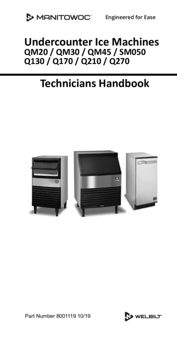
Section 3OperationComponent IdentificationICE THICKNESS PROBEFLOAT VALVE ASSEMBLYWATER DISTRIBUTIONBIN SWITCH MAGNETICE DAMPERWATER PUMPWATER TROUGHCONDENSER AIR FILTERON/OFF/WASH TOGGLE SWITCHPart Number 000001774 07/083-1
OperationSection 3Ice Making Sequence of OperationINITIAL START-UP OR START-UP AFTERAUTOMATIC SHUT-OFF1. Pressure EqualizationBefore the compressor starts the hot gas valve isenergized for 15 seconds to equalize pressures duringthe initial refrigeration system start-up.2. Refrigeration System Start-UpThe compressor starts after the 15-second pressureequalization, and remains on throughout the entireFreeze and Harvest Sequences. The hot gas valveremains on for 5 seconds during initial compressor startup and then shuts off.At the same time the compressor starts, the condenserfan motor (air-cooled models) is supplied with powerthroughout the entire Freeze and Harvest Sequences.The fan motor is wired through a fan cycle pressurecontrol, therefore it may cycle on and off. (Thecompressor and condenser fan motor are wired throughthe relay. As a result, any time the relay coil is energized,the compressor and fan motor are supplied with power.)FREEZE SEQUENCE3. PrechillThe compressor is on for 30 seconds prior to water flowto Prechill the evaporator.4. FreezeThe water pump starts after the 30-second Prechill. Aneven flow of water is directed across the evaporator andinto each cube cell, where it freezes.HARVEST SEQUENCE5. HarvestThe water pump de-energizes stopping flow over theevaporator. The rising level of water in the sump troughdiverts water out of the overflow tube, purging excessminerals from the sump trough. The hot gas valve alsoopens to divert hot refrigerant gas into the evaporator.The refrigerant gas warms the evaporator causing thecubes to slide, as a sheet, off the evaporator and into thestorage bin. The sliding sheet of cubes contacts the icedamper, opening the bin switch.The momentary opening and re-closing of the bin switchterminates the Harvest Sequence and returns the icemachine to the Freeze Sequence (steps 3 - 4).AUTOMATIC SHUT-OFF6. Automatic Shut-OffWhen the storage bin is full at the end of a HarvestSequence, the sheet of cubes fails to clear the icedamper and will hold it down. After the ice damper isheld open for 7 seconds, the ice machine shuts off. Theice machine remains off for 3 minutes before it canautomatically restart.The ice machine remains off until enough ice has beenremoved from the storage bin to allow the ice to fall clearof the damper. As the ice damper swings back to theoperating position, the bin switch re-closes and the icemachine restarts (steps 1 - 2), provided the 3-minutedelay period is complete.When sufficient ice has formed, the water flow (not theice) contacts the ice thickness probe. Afterapproximately 7 seconds of continual water contact, theHarvest Sequence is initiated. The ice machine cannotinitiate a Harvest Sequence until a 6-minute freeze timehas been surpassed.3-2Part Number 000001774 07/08
Section 3OperationEnergized Parts ChartCONTROL BOARD RELAYS123WATERHOT GASRELAYPUMPVALVECOILINITIAL START-UP/START UP AFTERAUTO SHUT-OFF:RELAY3ACOMPRESSOR3BCONDENSER FAN MOTORLENGTHof “ON” FFONONON30Seconds1. PressureEqualization2. RefrigerationSystem Start-upFREEZESEQUENCE:3. Pre-Chill4. FreezeHARVESTSEQUENCE:ONOFFONONONUntil 7 sec.water contactwith icethicknessprobeOFFONONONONBin switchactivationOFFUntilbin switchre-closes5. HarvestAUTOMATIC SHUTOFF:OFFOFFOFFOFF6. Auto Shut-Off* Condenser Fan Motor: The fan motor is wired through a fan cycle pressure control, therefore, it may cycle on and off.Part Number 000001774 07/083-3
OperationSection 3Operational ChecksGENERALWATER FLOAT VALVE CHECKYour Manitowoc ice machine was factory-operated andadjusted before shipment. Normally, a newly installed icemachine does not require any adjustment.Before water will flow into the water trough the floatvalve shut-off must be in the OPEN position.To ensure proper operation, always follow theseOperational Checks when starting the ice machine:PRESS TOOPEN for the first time after a prolonged out of service period after cleaning and sanitizingRoutine adjustments and maintenance proceduresoutlined in this manual are not covered by the warranty.PRESS TOCLOSESIPHON SYSTEMTo reduce mineral build-up and cleaning frequency, thewater in the sump trough must be purged during eachharvest cycle.When the water pump de-energizes the level in thewater trough rises above the standpipe starting a siphonaction. The siphon action stops when the water level inthe sump trough drops. When the siphon action stops,the float valve refills the water trough to the correct level.Water LevelSiphon System CheckFollow steps 1 through 6 under water level check.SIPHONCAPWATERLEVELSTANDPIPEDRAIN3-4Part Number 000001774 07/08
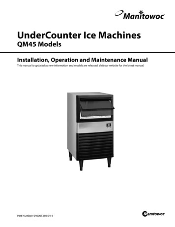
Section 3OperationWATER LEVEL CHECKICE BRIDGE THICKNESS CHECKCheck the water level while the ice machine is in the icemode and the water pump is running. The correct waterlevel is 1/4”(6.3mm) to 3/8” (9.5mm) below the top of thestandpipe a line in the water trough indicates the correctlevel.The ice thickness probe is factory-set to maintain the icebridge thickness at 1/8” (3.2 mm).SIPHON CAP1. Inspect the bridge connecting the cubes. It shouldbe about 1/8” (3.2 mm) thick.2. If adjustment is necessary, turn the ice thicknessprobe adjustment screw clockwise to increasebridge thickness, or counterclockwise to decreasebridge thickness.NOTE: Turning the adjustment 1/3 of a turn will changethe ice thickness about 1/16” (1.5 mm).ADJUSTING SCREWSET THE WATER LEVELTO THE LINE IN THEWATER TROUGHWater LevelThe float valve is factory-set for the proper water level. Ifadjustments are necessary:1/8” ICE BRIDGE THICKNESS1. Verify the ice machine is level (see page 2-4).2. Remove the siphon cap from the standpipe.3. Place the main ON/OFF/WASH toggle switch to theON position, and wait until the float valve stopsadding water.4. Adjust the water level to (1/4" to 3/8"5. (6.3 to 9.5 mm) below the standpipe) the line in6. the water trough:Ice Thickness CheckMake sure the ice thickness probe wire and the bracketdo not restrict movement of the probe.7. Loosen the two screws on the float valve brac
America's #1 Selling Ice Machine QM45 UnderCounter Model Ice Machines Part Number 000001774 07/08 0Front.fm Page 1 Thursday, July 17, 2008 3:41 PM. We reserve the right to make product improvements at any time. Specifications and design are subject to change without notice.