Transcription
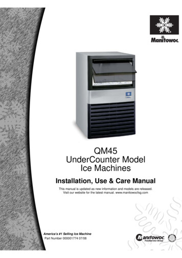
QM45 SeriesIce MachinesInstallation, Use, Care,and Service ManualThank you for selecting a Manitowoc Ice Machine, the dependability leader in ice making equipment andrelated products. With proper care and maintenance, your new Manitowoc Ice Machine will provide you withmany years of reliable and economical performance.We reserve the right to make product improvements at any time.Specifications and design are subject to change without notice.Part Number 00000177410/06
Safety NoticesProcedural NoticesWhen using or servicing these Ice Machines, be sureto pay close attention to the safety notices in thismanual. Disregarding the notices may lead to seriousinjury and/or damage to the ice machine.When using or servicing these Ice Machines, be sureto read the procedural notices in this manual. Thesenotices supply helpful and important information.Throughout this manual, you will see the followingtypes of safety notices:WARNINGText in a Warning box alerts you to a potentialpersonal injury situation. Be sure to read theWarning statement, and then proceed carefully.CAUTIONText in a Caution box alerts you to a situation inwhich you could damage the ice machine. Be sureto read the Caution statement, and then proceedcarefully.CAUTIONProper care and maintenance are essential formaximum ice production and trouble-free operationof your Manitowoc Ice Machine.Read and understand this manual. It containsvaluable care and maintenance information. If youencounter problems not covered by this manual,feel free to contact Manitowoc Ice, Inc. We will behappy to provide assistance.Throughout this manual, you will see the followingtypes of procedural notices:ImportantImportant boxes serve two functions.They call the operator’s attention to importantinformation.They also provide the service technician withinformation that may help perform a proceduremore efficiently. Disregarding this information mayslow down the work.NOTE: Text set off as a Note provides you withsimple, but useful, extra information.This manual covers the following model numbers:Self-Contained Air-Cooled:QM45AQM45AE
Table of ContentsTable of ContentsSection 1 - General InformationModel Numbers. 1-1Accessories . 1-1Model/Serial Number Location . 1-2Owner Warranty Registration Card. 1-3Warranty Coverage . 1-3Section 2 - Installation InstructionsGeneral. 2-1Ice Machine Dimensions. 2-1Location of Ice Machine . 2-2Ice Machine Heat of Rejection. 2-2Leveling the Ice Machine. 2-3Electrical Service. 2-5Water Service/Drains. 2-6Installation Checklist . 2-8Before Starting the Ice Machine. 2-8Section 3 - Ice Machine OperationComponent Identification . 3-1Ice Making Sequence of Operation . 3-2Ice Making Sequence of Operation Energized Parts Chart. 3-3Operational ChecksSiphon System . 3-4Water Level Check . 3-4Ice Bridge Thickness. 3-5i
Table of ContentsTable of Contents (cont.)Section 4 - MaintenanceGeneral. 4-1Cleaning and Sanitizing Procedure. 4-1Exterior Cleaning. 4-7Cleaning the Condenser . 4-7Removal from Service/Winterization. 4-8Section 5 - Before Calling for ServiceChecklist. 5-1Safety Limit Feature . 5-2Safety Limits. 5-3ii
Section 1General InformationSection 1General InformationModel NumbersThis manual covers the following 15/60/1230/50/1AccessoriesContact your Manitowoc distributor for theseoptional accessories:MANITOWOC CLEANER AND SANITIZERManitowoc Ice Machine Cleaner and Sanitizer areavailable in convenient 16 oz. (473 ml) and 1 gal(3.78 l) bottles. These are the only cleaner andsanitizer approved for use with Manitowoc products.Cleaner Part Number16oz94-0456-31 Gallon 94-0580-3Sanitizer Part number16oz94-0565-31 Gallon 94-0581-3ARCTICPURE WATER FILTER SYSTEMEngineered specifically for Manitowoc ice machines,ArcticPure water filters are an efficient, dependable,and affordable method of inhibiting scale formation,filtering sediment, and removing chlorine taste andodor.WarningPERSONAL INJURY POTENTIALDo not operate equipment that has been,misused, abused, neglected, damaged,or altered/modified from that of originalmanufactured specifications.1-1
General InformationSection 1Model/Serial Number LocationRecord the model and serial number of your icemachine in the space provided below. These numbersare required when requesting information from yourlocal Manitowoc distributor, service representative,or Manitowoc Ice, Inc.The model and serial number are listed on theOWNER WARRANTY REGISTRATION CARD.They are also listed on the MODEL/SERIALNUMBER DECAL affixed to the ice machine.MODEL/SERIALNUMBER PLATEMODEL/SERIALNUMBER PLATESV1732Model/Serial Number LocationIce MachineModel NumberSerial Number1-2
Section 1General InformationOwner Warranty Registration CardGENERALThe packet containing this manual also includeswarranty information. Warranty coverage begins theday your new ice machine is installed.ImportantComplete and mail the OWNER WARRANTYREGISTRATION CARD as soon as possible tovalidate the installation date.If you do not return your OWNER WARRANTYREGISTRATION CARD, Manitowoc will use thedate of sale to the Manitowoc Distributor as the firstday of warranty coverage for your new ice machine.Commercial Warranty CoverageGENERALThe following Warranty outline is provided for yourconvenience. For a detailed explanation, read thewarranty bond shipped with each product.Contact your local Manitowoc representative orManitowoc Ice, Inc. if you need further warrantyinformation.PARTS1. Manitowoc warrants the ice machine againstdefects in materials and workmanship, undernormal use and service for three (3) years fromthe date of original installation.LABOR1. Labor required to repair or replace defectivecomponents is covered for three (3) years fromthe date of original installation.EXCLUSIONSThe following items are not included in the icemachine’s warranty coverage:1. Normal maintenance, adjustments and cleaning asoutlined in this manual.2. Repairs due to unauthorized modifications to theice machine or use of non-standard parts withoutprior written approval from Manitowoc Ice, Inc.3. Damage caused by improper installation of theice machine, electrical supply, water supply ordrainage, or damage caused by floods, storms, orother acts of God.4. Premium labor rates due to holidays, overtime,etc.; travel time; flat rate service call charges;mileage and miscellaneous tools and materialcharges not listed on the payment schedule.Additional labor charges resulting from theinaccessibility of equipment are also excluded.5. Parts or assemblies subjected to misuse, abuse,neglect or accidents.6. Damage or problems caused by installation,cleaning and/or maintenance proceduresinconsistent with the technical instructionsprovided in this manual.AUTHORIZED WARRANTY SERVICETo comply with the provisions of the warranty, arefrigeration service company qualified andauthorized by your Manitowoc distributor, or aContracted Service Representative must perform thewarranty repair.NOTE: If the dealer you purchased the ice machinefrom is not authorized to perform warranty service,contact your Manitowoc distributor or ManitowocIce, Inc. for the name of the nearest authorizedservice representative.SERVICE CALLSNormal maintenance, adjustments and cleaning asoutlined in this manual are not covered by thewarranty. If you have followed the procedures listedon page 5-1 of this manual, and the ice machine stilldoes not perform properly, call your authorizedservice company.1-3
General InformationSection 1Residential Warranty CoverageWHAT DOES THIS LIMITED WARRANTY COVER?WHAT IS NOT COVERED?Subject to the exclusions and limitations below, ManitowocIce, Inc. (“Manitowoc”) warrants to the original consumer thatany new ice machine manufactured by Manitowoc (the“Product”) shall be free of defects in material or workmanshipfor the warranty period outlined below under normal use andmaintenance, and upon proper installation and start-up inaccordance with the instruction manual supplied with theProduct.This limited warranty does not cover, and you are solelyresponsible for the costs of: (1) periodic or routinemaintenance, (2) repair or replacement of the Product or partsdue to normal wear and tear, (3) defects or damage to theProduct or parts resulting from misuse, abuse, neglect, oraccidents, (4) defects or damage to the Product or partsresulting from improper or unauthorized alterations,modifications, or changes; and (5) defects or damage to anyProduct that has not been installed and/or maintained inaccordance with the instruction manual or technicalinstructions provided by Manitowoc. To the extent thatwarranty exclusions are not permitted under some state laws,these exclusions may not apply to you.HOW LONG DOES THIS LIMITED WARRANTYLAST?Ice Machine - Twelve (12) months from the sale dateWHO IS COVERED BY THIS LIMITED WARRANTY?This limited warranty only applies to the original consumer ofthe Product and is not transferable.WHAT ARE MANITOWOC ICE’S OBLIGATIONSUNDER THIS LIMITED WARRANTY?If a defect arises and Manitowoc receives a valid warrantyclaim prior to the expiration of the warranty period,Manitowoc shall, at its option: (1) repair the Product atManitowoc’s cost, including standard straight time laborcharges, (2) replace the Product with one that is new or at leastas functionally equivalent as the original, or (3) refund thepurchase price for the Product. Replacement parts arewarranted for 90 days or the balance of the original warrantyperiod, whichever is longer. The foregoing constitutesManitowoc’s sole obligation and the consumer’s exclusiveremedy for any breach of this limited warranty. Manitowoc’sliability under this limited warranty is limited to the purchaseprice of Product. Additional expenses including, withoutlimitation, service travel time, overtime or premium laborcharges, accessing or removing the Product, or shipping arethe responsibility of the consumer.HOW TO OBTAIN WARRANTY SERVICETo obtain warranty service or information regarding yourProduct, please contact us at:MANITOWOC ICE, INC.2110 So. 26th St.,P.O. Box 1720,Manitowoc, WI 54221-1720Telephone: 920-682-0161 Fax: 920-683-7585www.manitowocice.com1-4EXCEPT AS STATED IN THE FOLLOWING SENTENCE,THIS LIMITED WARRANTY IS THE SOLE ANDEXCLUSIVE WARRANTY OF MANITOWOC WITHREGARD TO THE PRODUCT.ALL IMPLIEDWARRANTIES ARE STRICTLY LIMITED TO THEDURATIONOFTHELIMITEDWARRANTYAPPLICABLE TO THE PRODUCTS AS STATED ABOVE,INCLUDING BUT NOT LIMITED TO, ANY WARRANTYOF MERCHANTABILITY OR OF FITNESS FOR APARTICULAR PURPOSE.Some states do not allowlimitations on how long an implied warranty lasts, so theabove limitation may not apply to you.IN NO EVENT SHALL MANITOWOC OR ANY OF ITSAFFILIATES BE LIABLE TO THE CONSUMER OR ANYOTHERPERSONFORANYINCIDENTAL,CONSEQUENTIAL OR SPECIAL DAMAGES OF ANYKIND (INCLUDING, WITHOUT LIMITATION, LOSS OFPROFITS, REVENUE OR BUSINESS) ARISING FROM ORIN ANY MANNER CONNECTED WITH THE PRODUCT,ANY BREACH OF THIS LIMITED WARRANTY, OR ANYOTHER CAUSE WHATSOEVER, WHETHER BASED ONCONTRACT, TORT OR ANY OTHER THEORY OFLIABILITY. Some states do not allow the exclusion orlimitation of incidental or consequential damages, so theabove limitation or exclusion may not apply to you.HOW STATE LAW APPLIESThis limited warranty gives you specific legal rights, and youmay also have rights that vary from state to state or from onejurisdiction to another.REGISTRATION CARDTo secure prompt and continuing warranty service, thiswarranty registration card must be completed and sent toManitowoc within thirty (30) days from the sale date.Complete the following registration card and send it toManitowoc at the address shown.
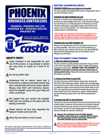
Section 2Installation InstructionsSection 2Installation InstructionsGeneralThese instructions are provided to assist the qualifiedinstaller. Check your local Yellow Pages for thename of the nearest Manitowoc distributor, or callManitowoc Ice, Inc. for information regarding startup services.ImportantFailure to follow these installation guidelines mayaffect warranty coverage.Ice Machine DimensionsQM-45 ICE MACHINES6.00”15.24 CMSV1679B3.35”8.6 CM2.88”7.3 CM3.85”9.8 CM22.34”56.74 CM6.19”15.7 CM5.94”15.1 CM3.75”9.5 CMSV1678EICE MAKINGWATER INLET30”76.2 CMICE MAKINGWATER/BIN DRAINELECTRICALINLETSV1735A19.69”50.1 CMSV17332-1
Installation InstructionsSection 2Location of Ice MachineIce Machine Heat of RejectionThe location selected for the ice machine must meetthe following criteria. If any of these criteria are notmet, select another location.SeriesHeat of Rejection*Ice Machine Air Conditioning**PeakQM-4517502600* B.T.U./Hour** Because the heat of rejection varies during the ice makingcycle, the figure shown is an average. The location must be indoors.The location must be free of airborne and othercontaminants.The air temperature must be at least 35 F (1.6 C),but must not exceed 110 F (43.4 C).The location must not be near heat-generatingequipment or in direct sunlight.The location must be capable of supporting theweight of the ice machine and a full bin of ice.The location must allow enough clearance forwater, drain and electrical connections in the rearof the ice machine.The location must not obstruct airflow through oraround the ice machine. Refer to the chart belowfor clearance 5” (203 mm)*5” (127 mm)*Self-ContainedWater-Cooled5” (127 mm)*5” (127 mm)*NOTE: The ice machine may be built into a cabinet.There is no minimum clearance requirement for thetop or left and right sides of the ice machine. Thelisted values are recommended for efficient operationand servicing only.CAUTIONThe ice machine must be protected if it will besubjected to temperatures below 32 F (0 C).Failure caused by exposure to freezingtemperatures is not covered by the warranty.See “Removal from Service/Winterization” on page4-10.2-2Ice machines, like other refrigeration equipment,reject heat through the condenser. It is helpful toknow the amount of heat rejected by the ice machinewhen sizing air conditioning equipment where selfcontained air-cooled ice machines are installed.
Section 2Installation InstructionsLeveling the Ice Machine1. Screw the leveling legs onto the bottom of the icemachine.2. Screw the foot of each leg in as far as possible.ImportantLevel the ice machine from front to back and sideto sideCAUTIONThe legs must be screwed in tightly to prevent themfrom bending.3. Move the ice machine into its final position.4. Level the ice machine to assure that the siphonsystem functions correctly. Use a level on top ofthe ice machine. Turn each foot as necessary tolevel the ice machine from front to back and sideto side.SV1704THREADLEVELING LEGINTO BASE OFCABINETChecking Ice Machine LevelTHREAD “FOOT”IN AS FAR ASPOSSIBLELeveling Leg and FootSV16062-3
Installation InstructionsTHIS PAGE INTENTIONALLY LEFT BLANK2-4Section 2
Section 2Installation InstructionsElectrical ServiceGENERALWARNINGAll wiring must conform to local, state and nationalcodes.VOLTAGEThe maximum allowable voltage variation is 10%of the rated voltage on the ice machine model/serialnumber nameplate at start-up (when the electricalload is highest).WARNINGThe ice machine must be grounded in accordancewith national and local electrical codes.FUSE/CIRCUIT BREAKERA separate fuse/circuit breaker must be provided foreach ice machine. Circuit breakers must beH.A.C.R. rated (does not apply in Canada).TOTAL CIRCUIT AMPACITYThe total circuit ampacity is used to help select thewire size of the electrical supply.The wire size (or gauge) is also dependent uponlocation, materials used, length of run, etc., so itmust be determined by a qualified electrician.WARNINGNever use an extension cord. If an outlet is notwithin reach of the ice machine’s power cord, havea proper amperage outlet wired closer to the icemachine.The 115/1/60 ice machines are factory pre-wiredwith a 6’ power cord, and NEMA 5-20P-plugconfiguration.The 230/50/1 ice machines are factory pre-wiredwith a 6’ power cord only, no plug is supplied.QM-45 ICE MACHINEIce ooledMaximumTotal AmpsFuse/CircuitBreaker155.2152.6For United Kingdom OnlyAs the colours of the wires in the mains lead of the appliance may not correspond withthe coloured markings identifying the terminals in your plug, proceed as follows: The wire which is coloured green and yellow must be connected to the terminal in theplug which is marked with the letter E or by the earth ground symbolor colouredgreen or green and yellow.The wire coloured blue must be connected to the terminal which is marked with theletter N or coloured black.The wire coloured brown must be connected to the terminal which is marked with theletter L or coloured red.2-5
Installation InstructionsSection 2Water Service/DrainsWATER SUPPLYLocal water conditions may require treatment of thewater to inhibit scale formation, filter sediment,remove chlorine, and improve taste and clarity.ImportantIf you are installing a Manitowoc Tri-Liminatorwater filter system, refer to the InstallationInstructions supplied with the filter system for icemaking water inlet connections.WATER INLET LINESFollow these guidelines to install water inlet lines: Do not connect the ice machine to a hot watersupply. Be sure all hot water restrictors installedfor other equipment are working. (Check valveson sink faucets, dishwashers, etc.)If water pressure exceeds the maximumrecommended pressure (80 psig), obtain a waterpressure regulator from your Manitowocdistributor.Install a water shut-off valve for the ice makingwater line.Insulate water inlet line to prevent condensation.2-6DRAIN CONNECTIONSFollow these guidelines when installing drain lines toprevent drain water from flowing back into the icemachine and storage bin: The ice machine comes equipped with a vinyldrain hose for use with floor drains.The floor drain must be large enough toaccommodate drainage from all drains.Insulate the bin drain to prevent condensation.Drain lines must have a 1″ (2.5 cm) drop per 40″(1 meter) of run, and must not create traps.ImportantThe Commonwealth of Massachusetts requires thatall water-cooled models must be connected only toa closed loop, cooling tower system.
Section 2Installation InstructionsWATER SUPPLY AND DRAIN LINE SIZING/CONNECTIONSCAUTIONPlumbing must conform to state and local codes.LocationWaterTemperatureWaterPressureIce MachineFittingIce MakingWater Inlet33 F (0.6 C) Min.90 F (32.2 C) Max.20 psi (137.9 kPA) Min.80 psi (551.5 kPA) Max.3/8” Female PipeThreadBin Drain------Tubing Size Up to IceMachine Fitting3/8” (9.5 mm)minimum insidediameter3/4” (19.1 mm)N/AVinyl TubingTypical Water Supply Drain InstallationICE MAKING WATERINLET TUBING3/8″ MIN. I.D. (.95CM)WATER SHUTOFFVALVESV1735ICE MAKINGWATER/BIN DRAIN5/8″ I.D. (1.59CM)2-7
Installation InstructionsInstallation ChecklistIs the ice machine level?Has all of the internal packing been removed?Have all of the electrical and water connectionsbeen made?Has the supply voltage been tested and checkedagainst the rating on the nameplate?Is there proper clearance around the icemachine for air circulation?Has the ice machine been installed whereambient temperatures will remain in the rangeof 35 - 110 F (1.7 - 43.3 C)?Has the ice machine been installed where theincoming water temperature will remain in therange of 33 - 90 F (0.6 - 32.2 C)?Are all electrical leads free from contact withrefrigeration lines and moving equipment?Has the owner/operator been instructedregarding maintenance and the use ofManitowoc Cleaner and Sanitizer?Has the owner/operator completed the warrantyregistration card?Has the ice machine and bin been sanitized?Has this manual been given to theowner/operator?2-8Section 2Before Starting the Ice MachineAll Manitowoc ice machines are factory-operatedand adjusted before shipment. Normally, newinstallations do not require any adjustment.To ensure proper operation, follow the OperationalChecks on page 3-4 of this manual. Starting the icemachine and completing the Operational Checks arethe responsibilities of the owner/operator.Adjustments and maintenanceprocedures outlined in this manualare not covered by the warranty.WARNINGPERSONAL INJURY POTENTIALDo not operate equipment that has been misused,abused, neglected, damaged, or altered/modifiedfrom that of original manufactured specifications.
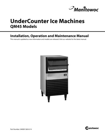
Section 3Ice Machine OperationIce Machine OperationComponent IdentificationICE THICKNESS PROBEFLOAT VALVE ASSEMBLYWATER DISTRIBUTION TUBESIPHON CAPEVAPORATORBIN SWITCH MAGNETSV1731AICE DAMPERWATER PUMPWATER TROUGHCONDENSER AIR FILTERON/OFF/WASHTOGGLE SWITCHSV1733COMPRESSOR COMPARTMENTACCESS SCREWS3-1
Ice Machine OperationSection 3Ice Making Sequence of OperationINITIAL START-UP OR START-UP AFTERAUTOMATIC SHUT-OFF1. Pressure EqualizationBefore the compressor starts the hot gas valve isenergized for 15 seconds to equalize pressures duringthe initial refrigeration system start-up.2. Refrigeration System Start-UpThe compressor starts after the 15-second pressureequalization, and remains on throughout the entireFreeze and Harvest Sequences. The hot gas valveremains on for 5 seconds during initial compressorstart-up and then shuts off.At the same time the compressor starts, the condenserfan motor (air-cooled models) is supplied with powerthroughout the entire Freeze and Harvest Sequences.The fan motor is wired through a fan cycle pressurecontrol, therefore it may cycle on and off. (Thecompressor and condenser fan motor are wiredthrough a relay. As a result, any time the relay coil isenergized, the compressor and fan motor are suppliedwith power.)FREEZE SEQUENCE3. PrechillThe compressor is on for 30 seconds prior to waterflow to Prechill the evaporator.4. FreezeThe water pump starts after the 30-second Prechill.An even flow of water is directed across theevaporator and into each cube cell, where it freezes.When sufficient ice has formed, the water flow (notthe ice) contacts the ice thickness probe. Afterapproximately 7 seconds of continual water contact,the Harvest Sequence is initiated. The ice machinecannot initiate a Harvest sequence until a 6-minutefreeze lock has been surpassed.3-2HARVEST SEQUENCE5. HarvestThe water pump de-energizes stopping flow over theevaporator. The rising level of water in the sumptrough diverts water out of the over flow tube,purging excess minerals from the sump trough. Thehot gas valve also opens to divert hot refrigerant gasinto the evaporator.The refrigerant gas warms the evaporator causing thecubes to slide, as a sheet, off the evaporator and intothe storage bin. The sliding sheet of cubes contactsthe ice damper, opening the bin switch.The momentary opening and re-closing of the binswitch terminates the Harvest sequence and returnsthe ice machine to the Freeze Sequence (steps 3 - 4).AUTOMATIC SHUT-OFF7. Automatic Shut-OffWhen the storage bin is full at the end of a Harvestsequence, the sheet of cubes fails to clear the icedamper and will hold it down. After the ice damper isheld open for 7 seconds, the ice machine shuts off.The ice machine will remain off for 3 minutes beforeit can automatically restart.The ice machine remains off until enough ice hasbeen removed from the storage bin to allow the ice tofall clear of the damper. As the ice damper swingsback to the operating position, the bin switch recloses and the ice machine restarts (steps 1 - 2),provided the 3-minute delay period is complete.
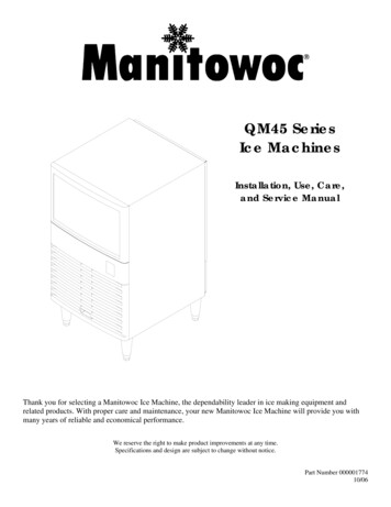
Section 3Ice Machine OperationQM45 SELF-CONTAINED AIR COOLED MODELSICE MAKING SEQUENCE OF OPERATIONCONTROL BOARD RELAYSRELAY123WATER PUMPHOT GASVALVERELAY FFONONON30SecondsINITIALSTART-UP/orSTART UPAFTERAUTO SHUTOFF:1. PressureEqualization2. RefrigerationSystem Start-up3A3B *LENGTHof “ON” TIMECOMPRESSOR CONDENSERFAN MOTORFREEZESEQUENCE:3. Pre-Chill4. FreezeHARVESTSEQUENCE:ONOFFONONONOFFONONONONUntil 7 sec.water contactwith icethicknessprobe5. HarvestBin switchactivation6. AUTO SHUTOFFUntilbin switchre-closesCondenser Fan Motor:OFFOFFOFFOFFOFFThe fan motor is wired through a fan cycle pressure control, therefore, it may cycle on and off.3-3
Ice Machine OperationSection 3Operational ChecksGENERALYour Manitowoc ice machine was factory-operatedand adjusted before shipment. Normally, a newlyinstalled ice machine does not require anyadjustment.To ensure proper operation, always follow theseOperational Checks when starting the ice machine: for the first time after a prolonged out of service period after cleaning and sanitizingWATER LEVEL CHECKCheck the water level while the ice machine is in theclean mode and the water pump is running. Thecorrect water level is 1/4" (6.3mm) to 3/8″ (9.5mm)below the top of the standpipe.SIPHON CAP1/4” TO 3/8″(6.3 TO 9.5 MM) BELOW TOP OFSTANDPIPERoutine adjustments and maintenance proceduresoutlined in this manual are not covered by thewarranty.SV1689-2SIPHON SYSTEMTo reduce mineral build-up and cleaning frequency,the water in the sump trough must be purged duringeach harvest cycle.When the water pump de-energizes the level in thewater trough rises above the standpipe starting asiphon action. The siphon action stops when thewater level in the sump trough drops below thesiphon cap. When the siphon action stops, the floatvalve refills the water trough to the correct level.Siphon System CheckFollow steps 1 through 6 under water level check.Water LevelThe float valve is factory-set for the proper waterlevel. If adjustments are necessary:1. Verify the ice machine is level (see page 2-3).2. Remove the siphon cap from the standpipe.3. Place the main ICE/OFF/WASH toggle switch tothe WASH position, and wait until the float valvestops adding water.4. Adjust the water level to 1/4" (6.3mm) to 3/8"(9.5mm) below the standpipe:A Loosen the two screws on the float valvebracket.WATER LEVELSIPHONCAP5. Move the main ICE/OFF/ WASH toggle switchto the OFF position. The water level in the troughwill rise above the standpipe and run down thedrain.STANDPIPEDRAINSV1689-23-4B Raise or lower the float valve assembly asnecessary, then tighten the screws.6. Replace the siphon cap on the standpipe, andverify water level and siphon action by repeatingsteps 3 through 5.
Section 3Ice Machine OperationICE THICKNESS CHECKThe ice thickness probe is factory-set to maintainthe ice
QM45 Series Ice Machines Installation, Use, Care, and Service Manual Thank you for selecting a Manitowoc Ice Machine, the dependability leader in ice making equipment and related products. With proper care and maintenance, your new Manitowoc Ice Machine will provide you with many years of reliable and economical performance.